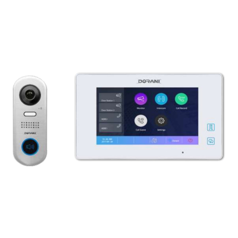
Dorani Limited DORVT Manual

DORANI TOUCH
VIDEO INTERCOM SYSTEM
INSTALL MANUAL
MODEL: DORVT
2 WIRE SYSTEM
WW.DORANI.COM.AU
Dorani (PJM Sales) –03 9357 0942
4/1 Merri Concourse, Campbellfield, Victoria 3061

2
KNOW YOUR MONITOR
WiFi Menu
WiFi Status
SIP Menu
Connection
Status
Shortcut
Menu
Call Scene Menu
Functions of
Diverting to Mobile
Settings Menu
All Installer Setting
Lock Release
Monitor Menu
Monitoring of Door
Stations
Call Record Menu
Reviewing of picture
Memory
Intercom Menu
Calling Other
Monitors in System
Settings –Volume, Brightness, Contrast
Snapshot –Takes a Snapshot Image of Screen
Unlock Lock 1 or Lock 2
Talk –Starts the communication to the door station
Identifies Door
Station Number
Calling
Back Button
Exit
Unlock Lock 1

3
INSTALLATION
THE MONITOR WILL TAKE APPROXIMATELY 2 MINUTES TO POWER UP
CABLE
Cable diameter of 1mm2 Stranded (twisted) MUST be used to achieve distances specified.
Recommended: 4 Core Security - 14/020 2 Conductors per Bus Line Wire
Cat 5 –All Conductors
Lock release will require an additional 2 cores for 12V Power feed to door station
Alternative Cables may be used
-Cable distances and picture quality may be compromised.
-Figure 8 Cable is NOT recommended for signal wires.
CONNECTIONS
The following connectors are supplied please ensure correct plugs are used
Wi-Fi and Internet
This Intercom can work as a standalone intercom, no requirements for Wi-Fi or Mobile app services
For Wi-Fi App connections the system requires quality internet and Wi-Fi at the monitor location
Speeds Greater than 1.2Mbps upload are recommended for quality and reliability
Many ISP (Internet Service Providers) restrict activity within supplied routers/modems. An IT
specialist may be required to “unlock” these restrictions. This may fall outside standard installation
and Dorani Tech support as it is a 3rd party device
Dorani bears NO responsibility for connection problems caused by 3rd party devices (modems,
routers, mobile devices) outside the Dorani product.
Warranty does not apply if the issues are 3rd party related
Dorani advise that connection to mobile devices enables communication and unlocking of your
intercom system from a remote location –please ensure your mobile device has a HIGH LEVEL of
security activated.
PROGRAMMING
WHEN MORE THAN 1 MONITOR IS INSTALLED THIS MUST BE PROGRAMMED refer page 11
WHEN MORE THAN 1 DOOR STATION IS INSTALLED THIS MUST BE PROGRAMMED refer page 12
LOCK RELEASE TIME IS 5 SECONDS TIME ADJUST refer page 10
Bus Modules
Door Station
Monitor

4
Loop Wiring
Cable
Dip Switches
Accessory Connector
2 Wires - Twisted
No Polarity
1mm² to achieve max distance
Dip Switch 6
ON = Last Monitor
All Other DIP Switches NOT USED
SW+ = 12V Positive Pulsing on Ring
SW- = 12V Negative on Ring
RING = Door Bell Normally Open
Input
GND = Door Bell Common Input
NC = Not Used
Door Bell is to Chime Monitor ONLY
REFER LOCK RELEASE
CONNECTIONS PAGE 9

5
Star Wiring
Cable
Dip Switches
Accessory Connector
2 Wires - Twisted
No Polarity
1mm² to achieve max distance
Dip Switch 6
ON = ALL Monitors
All Other DIP Switches NOT USED
SW+ = 12V Positive Pulsing on Ring
SW- = 12V Negative on Ring
RING = Door Bell Normally Open
Input
GND = Door Bell Common Input
NC = Not Used
Door Bell is to Chime Monitor ONLY
REFER LOCK RELEASE
CONNECTIONS PAGE 9

6
Legacy Wiring
Cable
Dip Switches
Accessory Connector
2 Wires - Twisted
No Polarity
1mm² to achieve max distance
Dip Switch 6
ON = ALL Monitors
All Other DIP Switches NOT USED
SW+ = 12V Positive Pulsing on Ring
SW- = 12V Negative on Ring
RING = Door Bell Normally Open
Input
GND = Door Bell Common Input
NC = Not Used
Door Bell is to Chime Monitor ONLY
Legacy Wiring Limitations
MAXIMUM of 1 x Door Station
MAXIMUM of 1 x DORVT22 + 1 x DORVT03
Cable Distance max 40m
Type of Cable will determine image Quality
REFER LOCK RELEASE
CONNECTIONS PAGE 9

7
LOCK CONNECTIONS
Standard and Keypad Door Station –DORVT11,12,13,14
Slimline Door Station –DORVT25
Lock Settings SLIMLINE –DORVT25
THIS DIP SETTING IS UNDER THE LABEL –REINSTALL STICKER AFTER CHANGING
LOCK RELEASE RELAY DORVT15
Time
Dip 5
Set By
Monitor
OFF
Manually
Closed
ON
Time
Dip 3
Dip 4
Set By
Monitor
OFF
OFF
5
Seconds
ON
OFF
10
Seconds
ON
ON
Set by Monitor
Relay Out
12VDC Out
Preferred Method
-Secondary Lock Release
-Allows for timed Press to Exit
-Enables lock release from remote
location (internal to home) for
greater security
-12V 400mA Output
NOTE: Install loop between 12V and
Common to provide 12V output across
relay
Manual Set
5 Seconds
Manual Set
10 Seconds
Preferred Method
12VDC Out
Relay Out
Preset as Door 1
Lock 2
Adjust Door/Lock at
rear of the module
through DIP
settings

8
LOCK RELEASE SETTINGS MASTER MONITOR DORVT22
SETTINGS –MASTER MONITOR DORVT22
Page ½ Button
Call Tune
Adjust Call Tune Settings of each door
station individually, and intercom tones
Adjust ringing time of door stations
General
Adjust Date/Time
Adjust Monitor ON time
Change Shortcut bar on LHS of monitor
SD Card Settings/Format
Page ½ Button
Enter Settings Meny
Enter Installer Menu
Press Page ½ Button
Adjust Lock Time
Adjust Normally Open / Closed
Installer
Enabling Intercom Function
System Settings (Installer level Code 12345678
Adjusts Divert Time, Resolution
Adjust lock Settings

9
ADDING SLAVE MONITORS–SLAVE MONITOR DORVT03
Slave Monitor Settings:
Slave 1 Type 8001 Press OK BEEP Type 8006 Press OK BEEP EXIT
Slave 2 Type 8002 Press OK BEEP Type 8006 Press OK BEEP EXIT
Slave 3 Type 8003 Press OK BEEP Type 8006 Press OK BEEP EXIT
Notes on additional monitors:
The system is designed to have 2 monitors alight and display images on initial call, all monitors in the
system will ring; pressing of non-imaged monitors will enable communication with the door station
On smaller cable runs, additional monitors may be able to be programmed to alight on call - Dorani places
no Guarantee on this feature
Step 1:
Press Dorani Symbol
Step 2:
Press and Hold Lock
button
Installer Setup Page
Should Appear
Exit
Wireless
Enabling Wi-Fi
SIP (Diversion) Configuration
SIP Testing (Tools)
About
Shows the Monitor Information
Firmware
IP Address

10
ADDING ADDITIONAL DOOR STATIONS
Keypad Doors (DORVT13,14)
1234 # 12 # Door Number # * Door 1 = 0 Door 2 = 1 Door 3 = 2 Door 4 = 3
Non - Keypad Doors (DOVT010,11)
Remove front fascia cover
The next steps need to be done QUICKLY
Power up Door station –Instantly press TOP button for 3 seconds - The system should beep and flash
Press and hold BOTH buttons for 3 seconds - the system should beep and the light should go out.
Press TOP button ONCE - it should beep 1 time = Door 1
Press TOP button TWICE - it should beep 2 times = Door 2
Press TOP button THREE TIMES - it should beep 3 times = Door 3
Press TOP button FOUR TIMES - it should beep 4 times = Door 4
Power off once completed OR wait 10 seconds without pressing any buttons
Slimline Door Stations (DORVT25)
THIS DIP SETTING IS UNDER THE LABEL –REINSTALL STICKER AFTER CHANGING
Use Dip Switches to Address station
Door
Dip 1
Dip 2
1
OFF
OFF
2
ON
OFF
3
OFF
ON
4
ON
ON
Door 1
Door 2
Door 3
Door 4

11
REMOTE DEVICE CONNECTION
Step 1 - Connect Device to Wi-Fi
Press WiFi Menu Button to bring the WiFI Settings Page
Connection Status
Step 2 - Download The App
Download the 2-Easy App onto your mobile device
Allow all request from the App to ensure connectivty.
Put mobile device on 4G for complete testing remote
from local network
Turn Switch to ON
Press WLAN Setting to Open Wireless Search
Setting
-Select you desired network
-Input Password
-Press Connect Button
If connection fails, please check correct SSID and
password.
The Wi-Fi Network should be shown at the bottom
of the monitor.
= Unable to access internet/server
= Connection to server OK
= NO connection to Wi-Fi
= Wi-Fi Level

12
Step 3 –Link the Monitor to the Device
Press PC Symbol to Open the SIP Menu page as below
The App should now say Account Registered
Step 4 –Setting Diversion
Enter the Call Scene Menu
The system has 5 different mode operations, 3 functions relate to the diversion
1) Normal = No Diversion to Mobile Device
2) Divert if Not Answered = Divert after time (default 20 Seconds)
3) Divert Always = Instant Divert (no internal monitor ringing)
NOTE: If Diversion occurs, press the Talk symbol to cancel the diversion and answer on the monitor.
Enable Simultaneous Video on Monitor and Mobile Device
When in the
Assistant Page of
the APP
Press Scanner
Button
Scan QR Code on
Monitor
Press Save
Note: You can
manually enter all
settings
Talk Symbol
ck 1
Enter Settings Menu
General Menu
Press Page ½ Button
Enable Screen on in Divert
Enter the Call
Scene Menu

13
KEYPAD DOOR STATION PROGRAMMING
Setting Notes:
Substitute 1234 for Installer Code
3 Beeps = Incorrect setting, code or location
Long Beep = Correct
* = Exit Programming
Default Installer Code= 1234 New Installer Code ___________
Program New Installer Code
1234 # 01 # New Master Code # * *
Program New User Code Lock 1 (Locations 20-29) New Code
1234 # 20 # New User Code # * Location 20 Default Code = 2580 ____________
1234 # 21 # New User Code # * ____________
1234 # 22 # New User Code # * ____________
Program New User Code Lock 2 (Locations 60-69) New Code
1234 # 60 # New User Code # * Location 60 Default Code = 0852 ____________
1234 # 61 # New User Code # * ____________
1234 # 62 # New User Code # * ____________
Lock Time (1 time for both locks)
1234 # 03 # Time (e.g 01) # * Default Time = 05
Defaulting Keypad with Code
1234 # 00 # 1234 # Wait 10 Seconds (Beep will be heard) *
Defaulting Keypad without Code
Power Down Door Station
Press and hold call button and Power up System (Hold button for 3 seconds)
You will hear a short beep, short beep, long beep, short beep
Release call button
Press and hold call button again for 3 seconds
You will hear a long beep, short beep
Release call button
Press and hold call button again for 3 seconds
You will hear a long beep and the light will change to green
Release call button
System is now defaulted

14
CONGRATULATIONS, on your new Dorani Video Intercom Product
Dorani Video Intercoms pride themselves on providing innovative solutions in domestic, commercial and
apartment video intercom systems.
We endeavour to provide all of our clients with the highest level of customer service, and ongoing
product support.
We value your feedback, and provide you with our warranty details below.
Warranty
All Dorani Video Intercom products come with a limited 24 month warranty from time of initial
purchase.
Damage caused by incorrect installation, negligence, abuse or malicious damage is not covered.
Damage from power strikes, surges, insect or vermin damage is not covered.
If you have any queries on the warranty of your product please do not hesitate in calling your installer or
local distributor found on our website dorani.com.au.
WWW.DORANI.COM.AU
Dorani (PJM Sales) –03 9357 0942
4/1 Merri Concourse, Campbellfield, Victoria 3061
Other manuals for DORVT
2
Table of contents
Other Dorani Limited Intercom System manuals
Dorani Limited
Dorani Limited DORVT22 Instruction Manual

Dorani Limited
Dorani Limited DORVT User manual
Dorani Limited
Dorani Limited 700 SERIES Instruction Manual

Dorani Limited
Dorani Limited C5 User manual

Dorani Limited
Dorani Limited DORVT Manual

Dorani Limited
Dorani Limited 600 Series User manual

Dorani Limited
Dorani Limited Two-Wire User manual

Dorani Limited
Dorani Limited TOUCH Owner's manual