Dorani Limited DORVT Manual

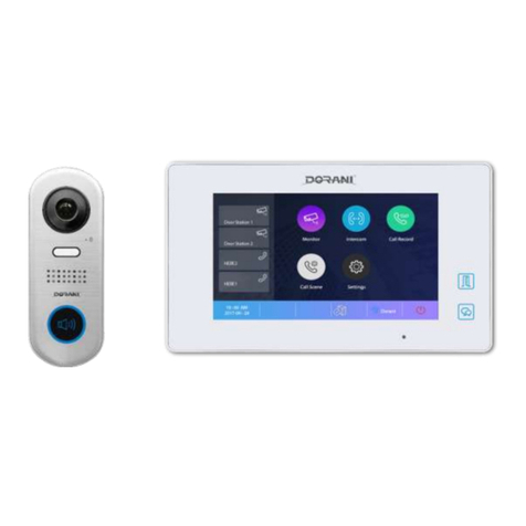
DORANI TOUCH
VIDEO INTERCOM SYSTEM
INSTALL MANUAL
MODEL: DORVT
2 WIRE SYSTEM
WWW.DORANI.COM.AU
Dorani (PJM Sales) –03 9357 0942
4/1 Merri Concourse, Campbellfield, Victoria 3061

2
FEATURES
-True Touch Screen functionality
-4 x Door station connectivity
-4 x Internal Monitors connectivity (SEE NOTE)
-Video Memory Recording (with addition of Micro SD Card)
-2 Door Releases from the 1 Door Station (with DORV15 )
-Auto Divert to Mobile when not at home (with DORVT05/06 Installed)
-2 Camera - CCTV Viewing from monitors
-Internal monitor paging and broadcasting
-Integrated Access Keypad Available
-DIN Rail Modular design
-Multiple cabling methods - star or looped (please see diagrams)
Note: The system is designed to have 2 monitors alight and display images on
initial call, all monitors in the system will ring. Pressing of non-imaged monitors
will enable communication with the door station
On smaller cable runs, additional monitors may be able to be programmed to
alight on call - - Dorani places no Guarantee on this feature
COMPONENTRY
DORVT01 7” LCD Touch Kit with Surface Door Station
DORVT02 7” LCD Touch Kit with Flush Door Station
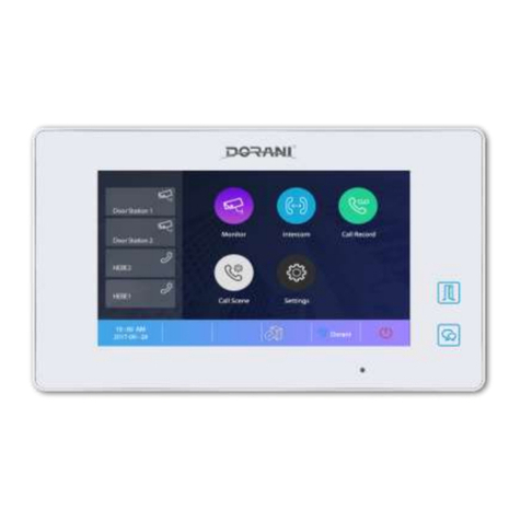
DORVT03 7” LCD Touch Screen Monitor
DORVT04 4 Way Monitor OR Door Station Branch Controller
DORVT06 PSTN Phone Line Interface
DORVT07 CCTV 2 Wire Camera
DORVT08 CCTV Module
DORVT09 Power Supply Module
DORVT10 Audio Door
DORVT11 Surface Mount Door Station
DORVT12 Flush Mount Door Station
DORVT13 Surface Mount Access Control Door Station
DORVT14 Flush Mount Access Control Door Station
DORVT15 Additional Lock Relay Module
CABLE
Cable diameter of 1mm2 Stranded (twisted) MUST be used to achieve distances
specified.
Recommended: 4 Core Security - 14/020 2 Conductors per Bus Line Wire
Lock release will require an additional 2 cores for 12V Power feed
to door station
Alternative Cables may be used –Cable distances and picture quality may be
compromised. Do NOT use Figure 8 Cable for signal wires.
3
CABLE DIAGRAMS
To Achieve Maximum Distances Quoted 1.0mm Twisted Cable is required
Additional Figure 8 required for 12V DC Supply to Strike
Image 1.1: Looped System
Image 1.2: Star System
Image 1.3: Legacy Wiring
Note: Cable and Cable Distances Vary due to type and style used. Achieve MAXIMUM
conductor size where possible (e.g. Common conductors where possible)
1 Door + 2 Monitors MAXIMUM
MonitorMonitor Monitor Monitor
BUS
Power
Supply
Outdoor
Station
DS IM
Latch
Power
Gate/
Latch
70m 70m
BUS
Green Connections
No Polarity
MonitorMonitor Monitor Monitor
BUS
Power
Supply
Outdoor
Station
DS IM
Latch
Power
Gate/
Latch
70m 70m
Dip 6 = ON
Last Monitor
Additional Supply & Cable required for
Latch/Mag Lock
See Door Station Connections
A B C D
BUS
Green Connections
No Polarity
Monitor
Monitor
Monitor
BUS
Power
Supply
Outdoor
Station 1
DS IM
Latch
Power
Gate/
Latch
70m 30m
Monitor
4 Branch
Module
Dip 6 = ON
All Monitors
Additional Supply & Cable required for
Latch/Mag Lock
See Door Station Connections
MonitorMonitor
Outdoor
Station
Latch
Power
Gate/
Latch
BUS
Green Connections
No Polarity
MonitorMonitor
BUS
Power
Supply
Outdoor
Station
Latch
Power
Gate/
Latch
Approx 40m
Dip 6 = ON
Last Monitor
Additional Supply & Cable required for
Latch/Mag Lock
See Door Station Connections
DS

4
CABLING SECONDARY DOOR STATIONS
Image 2.1 Additional Doors
DOOR STATION CONNECTIONS
Image 3.1 Door Station Lock Connections
MONITOR STATION CONNECTIONS
Image 4.1 Monitor Station Connections
BUS
Green Connections
No Polarity
BUS
Power
Supply
Outdoor
Station 1
DS IM
Latch
Power
Gate/
Latch
70m
A B C D
4 Branch
Module
Monitor Connections
as per Star or Loop
Wiring
Outdoor
Station 2
Latch
Power
Gate/
Latch
Additional Supply & Cable required for
Latch/Mag Lock
See Door Station Connections
BUS PL S+ S- 1 2 3
12VDC Out
Max 250mA
BUS PL S+ S- 1 2 3
NO / C
Relay Contact
No Jumper Jumper
2 & 3
BUS PL S+ S- 1 2 3
No Jumper
HigherAmp Voltage Output
Normally Open
Relay Max 24V 1Amp
Strike
Power
Preferred Voltage Out Connection Relay Out (Motors) Option 250MA Out
REX
Momentary
5 Second Momentary Release ONLY
BUS 1 2 3 4 5 6 DIP 1 – 5 = NOT USED
DIP 6 = Video Match Impedance
Loop System – Last Monitor ON
Star System ALL Monitors ON
SW+ , SW = Door Bell Button Input
RING, GND = 12V Pulsing 50mA
3 x 1 Second Beeps in Call
NC = Not Used
5 Pin Connector
Dip Set

5
INSTALLER PROGRAMMING
Accessing Installer Setup
Touch Screen to bring up Main page
Press Dorani Symbol to show parameters
Press and Hold Door release button until Installer Setup keyboard is viewed
Monitor Address Programming
Set Monitor Address by typing the numbers below and pressing OK.
ON EACH MONITOR –EACH MONITOR MUST HAVE A DIFFERENT ADDRESS
Monitor Address On/Off Display on Call
Master 8000 8006/8007
Sub 1 8001 8006/8007
Sub 2 8002 8006/8007
Sub 3 8003 8006/8007
Note:
The system is designed for 2 monitors to alight on intercom call, all monitors will ring
and can answer the call if desired.
3rd and 4th monitors may alight on call if programmed, this is site dependant based on
cable lengths and types. If a lower quality video image is displayed, turn off monitors.
Door Station Address Programming
For when more than 1 door station is installed. The door station you set this too will
then enable the monitor to view this door station.
NON KEYPAD DOOR STATIONS:
Remove front fascia cover using screws on back
The next steps need to be done QUICKLY
Power up Door station whilst holding TOP (B) button in for 3 seconds. The system
should beep and flash)
Press and hold BOTH buttons for 3 seconds, the system should beep and the light should
go out.
Press TOP button ONCE (it should beep 1 time) = Door 1
Press TOP button TWICE (it should beep 2 times) = Door 2
Press TOP button THREE TIMES (it should beep 3 times) = Door 3
Press TOP button FOUR TIMES (it should beep 4 times) = Door 4
Power off once completed OR wait 10 seconds without pressing any buttons

6
KEYPAD DOOR STATIONS:
Type Master Code (Default) 1234 # - Keypad lights should be White
Type 14# - Keypad lights should be Yellow
Type 0# (Default) = Door 1 Lights should go green then white
Type 1# = Door 2 Lights should go green then white
Type 2# = Door 3 Lights should go green then white
Type 3# = Door 4 Lights should go green then white
A red keypad means the adress setting was incorrect.
Press * to exit.
AUDIO DOOR STATIONS:
This is programmed by Dip Switch Settings on the rear of the station.
Door 1 = NO Switches ON
Door 2 = Switch 1 ON
Door 3 = Switch 2 ON
Door 4 = Switch 1 + 2 ON
Lock Settings (to be done on monitor):
The system is designed with a Relay Contact through the PL & S+ Terminals on the door
station
A separate power supply is required if triggering a door gate release from these
contacts, if an electric motor is to be triggered no additional power supplies need to be
introduced.
These program changes affect ALL Door stations connected –the memory is held in the
door station, connect door stations and program individually if you require different
release times or release types for each door
Changing from Normally Open to Normally Close –Default = Normally Open
Enter the Installer Setup Page on the MASTER monitor
Normally Closed = Program 8011 and press OK
Normally Open = Program 8010 and press OK
Changing lock release time - Default = 1 Second
The time can be from 1 Second to 99 Seconds (8401 –8499)
Enter the Installer Setup Page on the MASTER monitor
1 Second = Program 8401 and press OK
99 Seconds = Program 8499 and press OK

7
KEYPAD DOOR STATION DEFAULTING
To Default all settings WITH Master Code
Master Code # 00 # Master Code # - Wait till lights change colour - * to exit
EG: If Master Code is Default (1234 # 00 # 1234 # WAIT)
To Default WITHOUT Master Code
Power Down Door Station
Press and hold call button and Power up System (Hold for 3 seconds)
You will hear a short beep, short beep, long beep, short beep
Release call button
Press and hold call button again for 3 seconds
You will hear a long beep, short beep
Release call button
Press and hold call button again for 3 seconds
You will hear a long beep and the light will change to green
Release call button
System is now defaulted

8
CONGRATULATIONS, on your new Dorani Video Intercom Product
Dorani Video Intercoms pride themselves on providing innovative solutions in
domestic, commercial and apartment video intercom systems.
We endeavour to provide all of our clients with the highest level of customer
service, and ongoing product support.
We value your feedback, and provide you with our warranty details below.
Warranty
All Dorani Video Intercom products come with a limited 24 month warranty from
time of initial purchase.
Damage caused by incorrect installation, negligence, abuse or malicious damage
is not covered.
Damage from power strikes, surges, insect or vermin damage is not covered.
If you have any queries on the warranty of your product please do not hesitate in
calling your installer or local distributor found on our website dorani.com.au.
WWW.DORANI.COM.AU
Dorani (PJM Sales) –03 9357 0942
4/1 Merri Concourse, Campbellfield, Victoria 3061
Other manuals for DORVT
2
Table of contents
Other Dorani Limited Intercom System manuals

Dorani Limited
Dorani Limited TOUCH Owner's manual

Dorani Limited
Dorani Limited C5 User manual

Dorani Limited
Dorani Limited DORVT Manual

Dorani Limited
Dorani Limited DORVT22 Instruction Manual

Dorani Limited
Dorani Limited 700 SERIES Instruction Manual

Dorani Limited
Dorani Limited Two-Wire User manual

Dorani Limited
Dorani Limited 600 Series User manual

Dorani Limited
Dorani Limited DORVT User manual