DETECTOR DORS 1100 9
DETECTOR DORS 1100
8
OPERATION WITH EXTERNAL
DORS 1010 TELEVISION MAGNIFIER
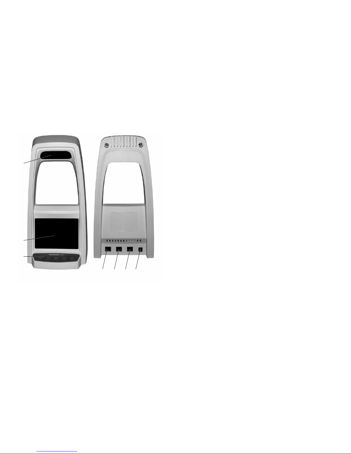
The DORS 1010 television magnifier
(Fig. 4) is connected to the input V1
and allows checking bank notes under
visible and IRlight. The television mag
nifier is activated by pressing the LIGHT
SELECT button at the upper part of its
casing. With this, the device switches
into the Zoom White mode (screening
with the white lighting), that allows
control of printing and microprinting
techniques, and also detection of prin
ting defects and erasures. At subsequ
ent pressing of the LIGHT SELECT but
ton, the Zoom White/Zoom IR mo
des will cycle with displaying the mode
on the screen. The infrared lighting
(Zoom IR mode) makes it possible to
investigate in details the location, sha
pe and structure of the IRmarks of the
bank note. In the Zoom IR mode the
screen picture is blackandwhite, and
in the Zoom White mode the screen
picture is color (if the color object is
available).
OPERATION WITH EXTERNAL
DORS 1020 TELEVISION MAGNIFIER
The DORS 1020 television magnifier
(Fig. 5) is connected to the input V1 and
allows checking the presence of
infrares (IR) and ultraviolet (UV)
marks in the reflected light, the surface
of banknotes and other objects in the
white oblique light, the presence of
micro prints. Connect the DORS 1020
television magnifier to V1 jack on the
rear panel of the device. The type of
the magnifier is detected automatically
at the moment of switching the device
on, that's why the cable of the magni
fier should be connected either to the
unplugged device or to the device in
standby mode. Switch on the detector.
Press the SELECT button on the upper
part of the magnifier. The detector will
change over to the next pressings of
the SELECT button on the magnifier
help to select the required illumination
source. The DORS 1020 television mag
nifier has three types of illumination:
white, IR and UV. For the onscreen
Fig. 4. DORS 1010 television magnifier
LIGHT SELECT button
Fig. 5. DORS 1020 television magnifier
SELECT button
menu of the monitor indicates the sta
tus of the illumination. Note Zoom
White corresponds to the white illumi
nation, note Zoom IR to the infrared
illumination, note Zoom UV to the ul
traviolet illumination. It is possible to
change over the device to observation
with the help of the internal IR camera
by means of the INPUT button.
Troubleshooting.
1. When working with the magnifier
it is not possible to switch on ultra
violet illumination. Probably the
magnifier was connected to the
already switched on device and
was not identified correctly. Put
the device in standby mode and
then turn it on again.
2. There is no picture from the exter
nal television magnifier or there is
no changing over to the corres
ponding video input by pressing
the SELECT button on the magni
fier. Probably the pin is not com
pletely inserted in V1 jack of the
device. Put the pin deep into the
jack till it stops.
VIDEO SIGNAL INPUT
FOR REMOTE DEVICES
The video input (V2) is designed for
connecting other visual control
devices such as security camera, etc.
VIDEO SIGNAL
OUTPUT
The video signal output (V3) is
designed for transmitting the video
signal to any auxiliary device with a
standard video input (camera, TV,
video recorder, etc.). To connect the
device to PC, use any video input
device and a special cable supplied by
the manufacturer.
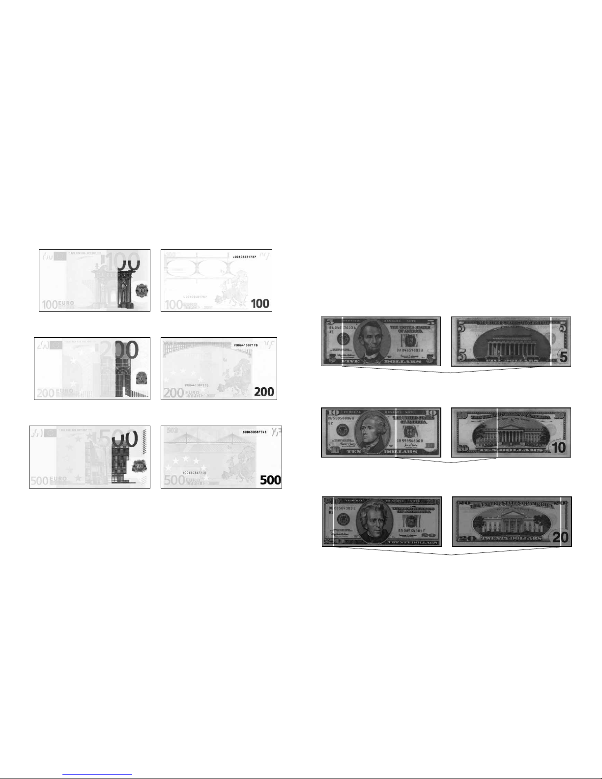
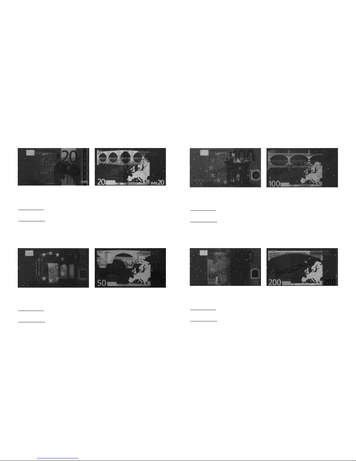
Layouts of bank note IR and UV marks
that are recommended for the control
with the device are given in Appendix
(page 12).