DORSEY BENCHMARK 16H User manual

Dorsey Metrology International
Optical Metrology Division
53 Oakley Street
Poughkeepsie, New York 12601
Telephone: (845) 454-3111 Fax: (845) 454-3140
BENCHMARK 16H
OWNERS MANUAL
Revised: Nov. 2015

16H Manual Page 2 Revised: 11/2015
Section No..
Introduction 1 . 0
Location 1 . 1
Operating Conditions 1 . 2
Electrical supply Information 1 . 3
Un-Packing Instructions 1 . 4
Machine Installation and Setup 2 . 0
Heidenhain Setup Instructions 2 . 1
Metlogix Setup Instructions 2 . 2
Installation and Setup Continued 2 . 3
Fitting Projection Lenses 2 . 4
Fitting Work holding Accessories 2 . 5
Fitting Work holding Accessories 2 . 4
Safety 3 . 0
Operating 4 . 0
Switching On 4 . 1
Pre Run Checks 4 . 2
Focusing 4 . 3
Profile Projection Intensity 4 . 4
Surface Illumination 4 . 5
Manual Table Adjustment 4 . 6
Helix Adjustment 4 . 7
Vertical Stage Adjustment 4 . 8
Angular Screen Measurement 4 . 9
Electronic Rotary Protractor 4 . 10
Additional Electrical Information 5 . 0
Connecting Electrical Supply 5 . 1
CONTENTS
Manual valid from S/N 0205/845 forward CONTENTS PAGE 1

16H Manual Page 3 Revised: 11/2015
Maintenance 6 . 0
Cleaning the lenses, screen and mirrors 6 . 1
Lamps replacement and adjustment 6 . 2
Fuse replacement 6 . 3
Magnification and MeasuringAccuracy check 6 . 4
Readout Accuracy 6 . 5
Lubrication 6 . 6
Technical Specifications 7 . 0
Lens Specifications for 16” machines 7 . 1
Footprint 7 . 2
Wiring Diagram 7 . 3
System Configuration Checklist 8 . 0
Limited Warranty Policy 9 . 0
Registration / RMA Form 9 . 1
CONTENTS
Manual valid from S/N 0205/845 forward CONTENTS PAGE 2

16H Manual Page 4 Revised: 11/2015
The Benchmark 16H Optical Comparator is a compact bench
mounted unit with a horizontal lens axis and a two mirror optical
system, projecting the “industry standard” erect and reversed
image on the screen.
The unit is designed to give the maximum possible screen size
and work stage capacity while retaining good operator access to
the controls and screen viewing area.
The comparator in standard form includes a screen with cross
lines, reticle marks (to easy verify magnification), protractor
markings and rotary vernier scale. It is equipped with a quick
change lens mount for lens magnifications from 10X to 100X,
Note: 5X lens has special mounting
Bright 250 Watt duel fiber optic surface illumination is also
standard equipment. Standard stage travel is 10” in the X Axis.
With optional extended travel to 24”. Standard YAxis travel is 6”
with travel limited to 5” for the thicker extended X Axis travel
stages. Focus travel is 2”.
Please visit “DorseyMetrology.com” to see our optical
comparator sales catalog for further information on options. Or
contact your local sales representative.
1.0 INTRODUCTION

16H Manual Page 5 Revised: 11/2015
1.1 LOCATION
1 . 2 Operating Conditions
This precision optical instrument is designed to work in a normal workshop
environment but it is important to locate the unit as far as possible from
sources of grinding grit, oil mist, and vibrations. Where possible locate the
projector with the screen facing away from direct sunlight and overhead
lighting that could interfere with the screen image.
This unit should be placed on a strong sturdy bench capable of
securely supporting a minimum of 550lbs/250Kg. with a point pressure
capability minimum of 165psi. Dorsey Metrology International optionally
supplies a cabinet/stand designed for this application. Contact Dorsey
Metrology International or your local sales representative for information
1 . 3 Electrical Supply Information
The standard Benchmark 16H is supplied to accept 110-120VAC, 50-60 Hz
main power. It may also be configured to accept either 220-240VAC, 50-
60HZ. Unless clearly labeled (next to the power input plug) this unit is
configured for 110-120VAC,50-60Hz. Listed below are wire color codes
110-120 VAC system Brown/Black Hot
Blue/White Neutral
Green Ground
220-240 VAC system Brown/Black Hot 1
Blue/White Hot 2
Green Ground
Note this unit must be plugged into an outlet rated at a minimum of 10 A
and must not be operated without an adequate ground connection.
.

16H Manual Page 6 Revised: 11/2015
1.4 UNPACKING INSTRUCTIONS
Benchmark 16H
Inspect for shipping damage
Please follow the instructions listed below to properly unpack your optical comparator. If shipping
damage becomes evident or questions arise during installation please call Dorsey Metrology
International at 1-800-549-4243 for immediate assistance.
1) Inspect the cardboard outer box and pallet for evidence of shipping damage. If evidence is
apparent immediately annotate damage on the receiving documentation and notify Dorsey
Metrology International at the number listed above.
2) Important: Your optical comparator packaging has been engineered to both preserve the
machine from corrosion and protect it from damage during transportation. For this reason
three of the four moving axes have been locked. They must not be unlocked until the machine
is in its place of use on a workbench. Moving or tilting the machine with any of the three axes
unlocked will cause damage to the machine. Please read the unpacking instructions before
removing the machine wrapping material.
3) Remove the outer banding material and protective cardboard carton from the pallet.
3a) Do not unlock any of the tagged machine locks at this time. Do not cut the banding material
located inside the plastic wrap. It is locking the Y Axis.
4) Remove the plastic moisture and corrosion barrier wrap. This material is treated with a metal
corrosion inhibitor. Again inspect for obvious shipping damage. Immediately contact Dorsey
Metrology if damage is present.
5) Any accessories or equipment is either under the plastic wrap or in the foam tray that the
machine is sitting in. Remove all accessories and place aside. Use the packing list and the
“system configuration checklist” to verify that you have all of the contents prior to throwing
away any packing material.
Caution:
The comparator must be lifted by the base handles or base. Under no circumstances should
the stage or the lamphouse be used to lift or position the comparator. Serious damage to the
stage or lamphouse will result if they are mishandled.
6) Warning! – placing the machine on a table or stand requires the machine to be Lifted
from the foam shipping tray. This is a 4 (strong) person operation. Please exercise
caution when performing this task. If lifting equipment is used. Please ensure it has been
certified to support a minimum of 500lbs./227Kg.
7) Place the comparator on a sturdy table. The table should be approximately 27”-29” high and
be capable of securely withstanding a combined load of at least 550 lbs./250Kg. with 4 point
pressure capability of approximately 165 PSI. Proceed to “Installation and Setup”
.

16H Manual Page 7 Revised: 11/2015
2.0 Machine Installation and
Setup
Section One
1) Once the machine is in place on the workbench (See “Unpacking Instructions”) cut and remove
the Y-Axis shipping lock. It is a strap wrapped around the machine preventing the Y-Axis from
moving.
1a) Level the machine front to back and side to side, using a standard quality level placed on the
stage. Be sure all four feet have pressure on them so the machine will not wobble when in
use. To adjust the feet, Use a19MM open end wrench or large adjustable wrench to loosen
the M12 lock nut if needed. Then use a M10 open end wrench (or small adjustable) and place
it on the bottom of the foot near the pad. You will see a flat section for the wrench. Tighten or
loosen as needed. When the machine is level lock the feet in position by tightening the M12
lock nuts.
2) Remove the small yellow Focus axis lock plate and two retaining screws. Then replace the
screws with the two large flat head screws. They are provided in the packaging along with the
X axis hand knob..
3) Remove the two X axis locks. They are located under the stage one on each end with a paper
tag attached to each. Use a 10MM deep socket or a M10 wrench to break the nut loose, Then
unscrew the set screw and remove it completely. Caution: Do not tighten the setscrew as this
will lift the stage and can cause damage.
NOTE: Do not remove the M8 socket head cap screws from under the stage top section! (two in the
front and two in the back.) They are not stage locks.
4) With the X axis locks removed and the leadscrew quick release lever to the right (dis engaged
from the leadscrew). Push the stage top, gently to the left and then to the right to center the
bearings along the travel. You will feel some resistance as the bearings are being pushed into
the correct position for the first time. After that the stage will glide freely.
5) Center the stage and flip the quick release lever to the left to lock the leadscrew nut onto the
threads of the leadscrew. Then install the X axis hand knob provided in the packing. To
secure the knob in place, use a 2.5MM hex wrench to tighten the knob setscrews against the
flats of the leadscrew end. Do not over tighten. Note: there are no hand knobs on motorized
machines.
5a) If you have a motorized machine connect the joystick cable and place the joystick on the tray.
6) Depending on what type of readout you have purchased follow either the,
“Heidenhain Setup Instructions” 7 Thru 11
or the
“Metlogix M2 Setup Instructions” 12 Thru 14

16H Manual Page 8 Revised: 11/2015
Machine Installation and Setup
Section Two
2 .1 “Heidenhain Setup Instructions”
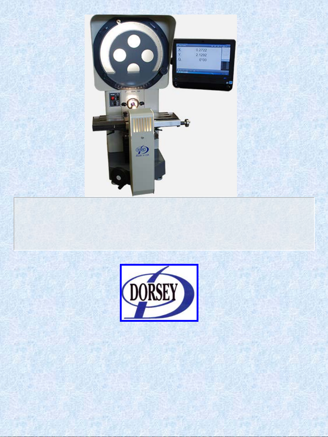
7) Attach the Digital Readout mounting arm to the right side of the comparator using four M4
socket head cap screws provided. 3MM hex wrench needed.
8) Mount the Digital Readout onto the DRO base using the four 10-32 X 3/8” socket head cap
screws provided. Then attach the DRO base to the DRO arm.
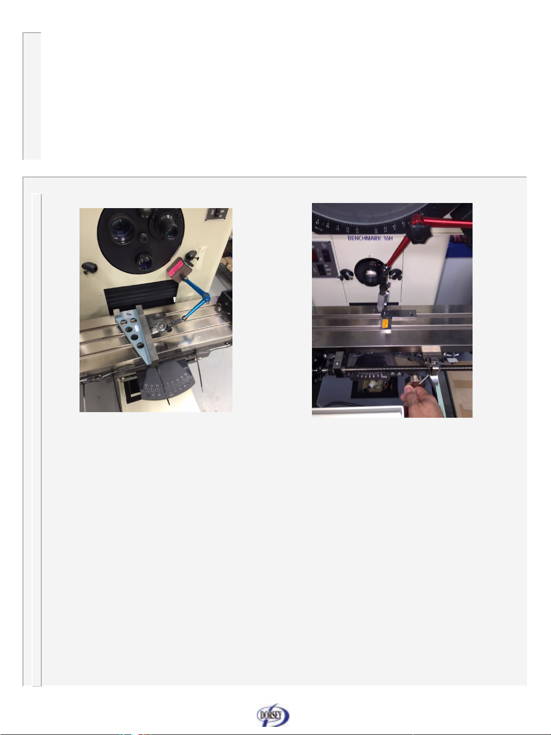
9) Connect the scale cables (marked) to the proper connector of the readout. Then connect the
fiber optic cables if equipped with edge detection.
10) Connect the special power cord to the comparator right side outlet then to the DRO.
11) Connect the power cord to the power module on the back of the comparator and then plug it into
the correct power supply. Please see the “Electrical Information” page for power
requirements. Turn on the comparator Main power switch (red) then turn on the DRO. Move
each axis to verify the scale connectors are on the proper axes. Proceed to Step 15.
2 . 2 “Metlogix M2 Setup Instructions”
12) Remove the “All In One” computer from the box and clamp the ball on the back of the computer
into the arm mounted on the side of the comparator. Adjust the monitor to the correct position.
Then tighten the arm clamp to hold it in place.
13) Locate the small round computer power cable and the USB cable from the right side of the
comparator and connect them to the back of the computer.
NOTE: The computer is a touch screen type. You do not need to connect the keyboard and mouse
that are supplied with it. They can be connected at a later date for custom DRO settings or to
use the computer for other than a DRO.
14) Connect the machine power cord from the power module on the back of the comparator to the
power supply. Please see the “Additional Electrical Information” page for power
requirements. Turn on the comparator Main power switch (red). Then turn on the computer
and launch the M2 measurement software by double clicking on the M2 icon. The DRO
screen will appear and you can move the X, Y , and Q (if equipped) Axes to test the function
of the machine.
NOTE: When the M2 software is opened it looks for the control box containing the software license.
The control box is located inside the comparator. Therefore the comparator power must be on
BEFORE the M2 software is opened or you will see a red message stating that “M2 has lost
communication with the box” (or other warning alerts) If this happens or the M2 readout
software is not working properly. Close the M2 software, cycle the power for the comparator
off for 10 seconds then switch the power back on. Re-launch the M2 software. If you are still
having problems restart the computer. Then repeat the start up sequence. Machine power first
then launch the M2 software. To avoid getting a error massage close the M2 software before
shutting off the comparator. Other programs on the computer can be used regardless of
machine power switch position. Proceed to Step 15.

16H Manual Page 9 Revised: 11/2015
2. Machine Installation and
Setup
Section Three
2 . 3 Installation and Setup Continued
15) With the main (Red) power switch on and the cardboard cover removed from the lens opening,
test the profile light switch by briefly switching to high and low. Center position is off.
CAUTION: without a lens in the machine the screen will be very bright. Do not look directly at the
screen when testing the lamp on high. Test the surface lighting by switching the surface light
on then off. It either light does not work properly please refer to the “Troubleshooting” section
of this manual.
16) With the main power switch on and no lens in the machine switch the profile illumination to low.
Note the position of the bulb element on the screen. It should be centered up and down and
left and right. If it is out of position either reseat the bulb in the socket or adjust the socket
position in the lamphouse using a 3MM hex wrench. CAUTION: The bulb is very hot.
I7) Insert a lens into the lens opening with the red dot of the lens ring aligned with the red dot on the
face of the machine. Then apply slight pressure uniformly around the lens ring while twisting
to the right (clockwise). The lens will twist to the right and stop with the lens red dot slightly to
the right at about the one O’clock position. To remove the lens turn left (counter clockwise)
until the red dots are aligned then remove the lens.
18) If the stage was bumped during installation it could be skewed. Check the stage helix vernier
(located under the X axis cover) it should indicate 0. If adjustment is needed. Loosen the two
helix clamps under the stage and place a magnetic indicator on the stage. Indicate from one
side of the lens ring to the other and twist the stage as needed. Lock the helix locks when
done.
A more accurate alignment method would be to place a 3” to 4” square or straight edge on the
stage perpendicular to one of the stage vees’ then place a magnetic .00005” indicator on the
face of the machine. With the contact point of the indicator against the side of the square or
straight edge. Move the focus forward and back while indicating along the side of the square
or straight edge. With the two locks loose, twist the stage as needed to adjust. For best results
obtain .00005” or better over the focal distance. Then tighten the stage locks. See “squaring
the focus axis” Pictures on the following page.

16H Manual Page 10 Revised: 11/2015
2. Machine Installation and
Setup
Section Four
Squaring the focus axis example one Squaring the focus axis example two
19) Verify screen magnification, adjust as required. Qualified personnel only
20) Verify DRO error compensation, adjust as required. Qualified personnel only
21) Your comparator was fully inspected and calibrated to a high degree of accuracy before it left
the factory. Please refer to the accompanying Calibration Certificate. To be sure there has
been no changes due to shipping, setup or environment. A qualified service person should
inspect the machine and issue a new certificate or validate the existing certificate.

16H Manual Page 11 Revised: 11/2015
2. Machine Installation and
Setup
Section Five
2 . 4 FITTING PROJECTION LENSES
All lenses are supplied with quick change bayonet type mounts. To
mount the lens, install lens in lens barrel and rotate lens clockwise
until it clicks into place.
To install the lens: insert the lens with the
red dots aligned, rotate the lens clockwise
approximately 15 degrees to lock the
lens in place
2 . 5 Fitting work holding accessories
Work holding accessories available for the 16H include combination
centers and vees, vertical glass plate work holder for the projection of
small flat components, rotary vice, and a wide selection of other items.
All of the accessories mount in the universal dove tail slot in the table
and are angular clamped in place with clamping screws. This type of
clamping accessory can be placed directly onto the table without
having to slide locking nuts in from the end of the table.
Dorsey Metrology International is also able to offer advice and
manufacturing facilities for special custom work-holding fixtures and or
custom options. Please Contact us with your requirements.
Locking
points

16H Manual Page 12 Revised: 11/2015
3.0 SAFETY
This equipment has been designed and manufactured so far as is
reasonably practical to allow its safe operation when used in accordance
with the following instructions.
The equipment must be used in a location that does not constitute a
hazard, where the operator and maintenance staff have free access to the
control and maintenance of the equipment, and are not subject to any
external hazards.
Services should be conducted by a qualified person, to approved safety
standards.
The electrical supply should be taken from a correctly rated source.
WARNING The equipment MUST NOT be operated without a secure
earth terminal connection.
Before connecting to a power supply or attempting to use the equipment,
all packaging must be removed including the transportation strap. Do not
connect or attempt to use any equipment showing obvious signs of damage
or deterioration and take extra care when switching on for the first time.
A person qualified for training should examine the equipment for operator
safety and provide training as needed by the operator for its safe and
correct use.

16H Manual Page 13 Revised: 11/2015
4.0 OPERATING
Section one
4 . 1 Switching On
Ensure that the projector is connected to the proper power supply. (Refer
to the “Additional Electrical Information” page for help).
The lamps are controlled by rocker switches located on the front panel of
the comparator body. Separate switches control the profile and surface
illumination lamps. The profile lamp uses a 2 position switch: down is low
intensity, while up is high intensity.
NOTE: Please refer to the separate operating instruction manual for the
various digital readout units available.
4 . 2 Pre-Run Checks
Ensure that the comparator is secure on its stand or on a substantial
bench. Having selected a lens of the required magnification and locked it
securely in position, locate the component to be inspected in a suitable
work holding fixture which must be securely clamped to the table, the
projector is now ready for use, proceed as follows:
4 . 3 Focusing
Focus is achieved by rotating the small hand wheel on the right hand side
of the stage knee. The lens focal plane is approximately mid-way along
the focus traverse, central to the dovetail slot in the table.
4 . 4 Profile Projection Intensity
Profile lighting is provided by a 24V 150W tungsten halogen lamp.
There are two profile light intensity levels, high or low, selected from the
rocker switch on the panel below the screen. Select the level that gives the
most comfortable viewing, according to the object projected and the
external lighting conditions prevailing.
An iris diaphragm and or green filter is available as an optional extra which
may be fitted direct onto the lamp house to reduce the level of reflection
from brightly polished surfaces e.g. ground threads, etc.

16H Manual Page 14 Revised: 11/2015
4 . 5 Surface Illumination
Illumination of surface features on solid objects is achieved through the
use of high intensity fiber optic light guides. These guides are adjustable
and can be extended by pulling on the cable ends protruding from either
side of the lens mount. They may be secured in place with the clamping
screws on the side of each of the guide blocks.
For the brightest reflected image, place the light guides as close as
possible to the face of the component to be inspected. Where components
have a directional surface finish, e.g. ground faces, the surface texture
should be placed at right angles to the table, this will give the brightest
reflected image on the screen.
As the fiber optic cable is a “cold light” source, the heat radiated to the
component under test is minimal.
4 . 6 Manual Table Adjustment “Quick Release”
The X axis of the stage has a quick release for coarse motion. This feature
should not be used to move the stage during a measuring routine. Also,
when the quick release is in use, the control knob of the X axis is disabled.
To use the quick release, rotate the lever to the furthest position to the
right. To re-engage the control knob, first make sure the stage is not
moving then rotate the lever to the furthest left position. (see the picture
below)
4. OPERATING
Section two
Engaged on threads,
for measuring
Not engaged on
threads, for fast
positioning.
NOTE: Motorized machines do
not require a “Quick Release “
and can use the high speed
joystick setting for quick traverse
and part positioning.

16H Manual Page 15 Revised: 11/2015
4. OPERATING
Section three
4 . 7 Stage Helix Adjustment
The top of the focus slide has a stage helix adjustment, which allows the
stage to be rotated horizontally. To do this the 2 locking clamps located
beneath the stage must first be loosened. The stage can now be rotated
+/- 15 degrees. The helix indicator (located under the X axis cover shows
the amount of rotation in 5’ increments. Once the desired helix is indicated,
tighten the locking clamps to hold this position.
To restore the helix to the zero (0) position, loosen the locking clamps and
rotate the helix adjustment to zero. Or for a more precise zeroing, use one
of the techniques in the “Machine Installation and Setup” section.
4 . 8 Vertical Stage Adjustment
Vertical adjustment of the work stage is by means of the large hand wheel
on the left below the work stage knee. Or joystick control for motorized
machines.
4 . 9 Mechanical Screen Angular Measurement
The screen vernier and protractor consists of a frosted glass screen
divided into four equal quadrants by precision cross lines and 360 Deg.
protractor markings. The screen is rotated by means of a small hand wheel
on the right of the screen. The mechanical venire protractor can then be
used to determine angles with 1 minute resolution.
4 . 10 Electronic Rotary Protractor (Optional)
The electronic rotary screen protractor is a screen encoder that sends screen
rotation information to the digital readout. The readout displays the current rotary
position of the screen .The readout can display rotary position in either degrees
and minutes or degrees decimal. (1/100 of a degree)
Please refer to the readout manual for instructions on how to change the display
mode or re-calibrate the rotary axis.

16H Manual Page 16 Revised: 11/2015
5.0 ADDITIONAL
ELECTRICAL INFORMATION
5 . 1 Connecting Electrical Supply
The standard Benchmark 16H is supplied to accept 110-120VAC, 50-60 Hz
main power. (NOTE: See section 1.4 for power requirements). It may also
be configured to accept 220-240VAC main power.
Use the following procedure to convert the machine power module for
alternative power input.
***CAUTION - READ THROUGH ALL OFTHE INSTRUCTIONS
BEFORE POWER CONVERSION ***
1. Remove the power cord from the power module on the back of the
comparator.
2. Slide up the clear plastic fuse cover.
3. On the inside, lift up the lever that says “fuse pull” (fuse ejector) which will
eject the fuse.
4. Lift this into the locking position (all the way up) It will eject the fuse and hold
the clear slide protector up in place. Remove the fuse and hold the plastic
cover up while moving the fuse ejector lever back down to its locking
position.
5. Read the side of the circuit board if it says 120 it is set for 110-120 VAC if it
says 240 it is set for 220-240 VAC.
6. To change the setting remove the board by first lifting the fuse ejector lever
and removing the fuse. Then lift the lever all the way up to the locking
position. Insert a small hex wrench or round object into the hole in the
printed circuit board and slowly pry it straight out. You can also use needle
nose plyers to gently grab the board and pull it straight out. Be careful not to
scratch the soldering.

16H Manual Page 17 Revised: 11/2015
5 . ADDITIONAL ELECTRICAL
INFORMATION
CONTINUED
7. Insert the card back in so when the lever is in the down position either “120”
is showing if your power supply is 110-120 VAC or “240” is showing if your
power supply is 220-240 VAC.
8. CAUTION! Do not use the 100 or 220 side of the printed circuit board.
These numbers should never show inside the power module with the lever
down. Using the 100 or 220 positions on the board will damage the
wiring.
9. With the board installed correctly for your power supply and the fuse ejector
lever pushed all the way down to the lock position. Reinstall the 10 Amp
fuse.
10. NOTE: changing the printed circuit board to a new voltage will also change
the power output of the “digital readout outlet” on the side of the comparator
to the “line voltage” (The same as the voltage going into the machine.) If
your readout is plugged into this outlet, Make sure your readout is
compatible with the main power supply (line) voltage before turning on the
power.
DRO outlet 120V showing in window Circuit Board

16H Manual Page 18 Revised: 11/2015
6.0 MAINTENANCE
SECTION ONE
6 . 1 Cleaning the lenses, screen and mirrors
Lenses: Any accumulated dust must be removed from the surface of the
lenses with a photographic lens brush.
The surface of the inner lens (projection or condenser) must not be
touched. The element of the projection lens facing the mirror is most
critical in this respect. A single finger mark on this surface will noticeably
degrade the quality of the projected image. It should be noted that the
projection lens element facing the work piece is far less critical in this
respect.
Any grease or finger marks may be removed with a new photographic
cleaning tissue. If necessary, the tissue may be moistened with methanol
or lens cleaning fluid to assist cleaning.
Screens:
All screens are made out of ground glass with printed cross lines. The cross lines
can be removed if the screen is not cleaned properly. We recommend that the
screens be cleaned only with soap (a mild non-lotion dishwashing solution) and
plenty of water. Use a lint free soft cotton cloth to gently clean. Wipe the bulk of
water with a (no lotion no oils) plain bathroom tissue paper then let the screen air
dry.

16H Manual Page 19 Revised: 11/2015
6. MAINTENANCE
SECTION TWO
DANGER! - When using methanol or alcohol for cleaning disconnect the
comparator from the power source and remove all sources of ignition
from the area. Wait for all vapors to thoroughly evaporate before re-
connecting the power.
WARNING! – To avoid damage. Never use polishes, window cleaning
aerosols, liquids or canned air (canned air can spritz out propellant
and damage the mirror.) when cleaning the mirrors. Do not use force.
Mirrors: Access to the mirrors is gained by removing the screen and or
side cover
The comparator uses “First Surface Mirrors” These mirrors have the
reflective coating on the top surface, unlike normal mirrors. This reflective
coating is only a few microns thick and can be easily damaged. Therefore
you should only clean the mirrors when the projected screen image has
degraded. Do not clean as part of “regular maintenance”. To remove “light
oil film or dust” from the mirror surfaces you can spray Methanol or alcohol
on plain (no lotion no oils) soft bathroom tissue paper until it is damp, then
wipe the mirror once in one direction. Then throw away that tissue and use
another wad. Going over the mirror again with the same (now dirty) tissue
will cause scratches. Use a new wad of tissue with each pass. Do not wipe
back and forth or in circles.
If the Mirror has metal dust or heavy oil or dirt you can flood the mirror with
methanol or alcohol. Place a large amount of paper towel under the mirror
to be cleaned. Then use a pump sprayer to flood the mirror with Methanol
or alcohol. The pressure from the sprayer will help to force the large
deposits off of the mirror. After this, immediately discard the wet paper
towels and finish cleaning the mirror using the above “light oil film or dust”
cleaning technique.

16H Manual Page 20 Revised: 11/2015
6. MAINTENANCE
SECTION THREE
6 . 2 Lamp Replacement and Adjustment
WARNING! This must be done with the power switched off and the
lamp cold.
PROFILE LAMP
To change the lamp first remove the lamp house cover. Remove the old bulb
by grasping and pulling the bulb directly up. Remove the new replacement
bulb from its box, With the bulb still in the plastic bag use scissors and cut
open the end of the bag near the two metal pins. Slide the bulb out slightly
to expose the pins. Use the bag to hold the bulb. Slide the pins of the bulb
into place. The ends of the pins should contact the ceramic evenly just
below the two metal contacts of the socket. Then remove the plastic bag
from the bulb.
Switch main power on, remove the objective lens, and set lamp intensity to
low. Verify that the lamp filament projected on the screen is centered over
the crosshairs both up and down and left and right. Re-seat lamp and or
adjust the ceramic holder if required.
If the lamp glass is accidentally touched, wipe the bulb immediately by
swabbing with methanol. The lamp operates at a high temperature and any
finger marks will be “fired” into the surface of the quartz reducing the output
and life of the lamp.
Bulb element in center of
screen no lens in place
Profile lamp shown in
correct position
Table of contents
Other DORSEY Measuring Instrument manuals