Doug Fleenor Design RERUN Series User manual

RERUN RACKMOUNT
DMX512 RECORDER
MODEL: RERUN-R1, RERUN-R2, RERUN-R3, RERUN-R4
OWNERS MANUAL
Doug Fleenor Design
396 Corbett Canyon Road
Arroyo Grande, CA 93420
(805) 481-9599
Manual Revision
July 2020

Page 2 of 12
PRODUCT DESCRIPTION
The Rerun Rackmount is a lighting control station capable of storing up to ten 40-minute shows on up to
4 universes. Shows are recorded by capturing the output of a DMX512 console. The recorded show start
and end points may be trimmed non-destructively. Each show can be set to hold the last look, loop to itself
or link to another show. Shows are started by pressing one of the ten show buttons.
The Rerun Rackmount can be built to support multiple universes of DMX512. As many as four universes
can be supported in a single 1U chassis. The Rerun-R1 supports 1 universe of DMX512, the Rerun-R2
supports 2 universes of DMX512, the Rerun-R3 supports 3 universes of DMX512, and the Rerun-R4
supports 4 universes of DMX512. Expansion units may be added via a 3-pin XLR connector on the rear
of the chassis in order to support additional universes.
The Rerun Rackmount occupies 1U of rackspace, and comes standard with rack ears for easy installation.
Also included is a clear security panel designed to block unintended button presses. Preset 10 remote
stations can be added to remotely select shows. Power to the Rerun Rackmount is provided by the
attached wall power supply.
The Rerun Rackmount system can work in conjunction with a lighting console, automatically switching
between recorded shows and console control. When the console generates DMX512, the Rerun
Rackmount retransmits the incoming DMX512 data. Thus the console operates normally. Upon loss of
DMX512 from the console, the Rerun Rackmount starts its previously active show.
Rerun also is available in an architectural version (model RERUN-A) and a portable version (model
RERUN-P). The Rerun Architectural and Rerun Portable units can each support one universe of DMX512
data.

Page 3 of 12
SPECIFICATIONS
DMX connectors: Gold plated 5 pin Neutrik D-1 Series XLR connectors or optional terminal blocks
Input Circuit: EIA-485 receiver (LT1785) with 120 ohm termination resistor between + Data &
- Data
Output Circuit: ESD protected EIA-485 transceiver (LT1785)
Isolation: None. DMX input(s) not isolated from DMX output(s).
Expansion circuit: Gold plated 3 pin female Neutrik D-1 Series XLR connector or optional terminal
block
I C (Inter-Integrated Circuit) Bus
2
Indicators: Ten green SHOW LEDs
One green PAUSE LED
One green LOOP LED
One yellow START LED
One yellow END LED
Up to four red INPUT/RECORD LEDs (One per universe)
User controls: Ten [SHOW] buttons
One [PAUSE] button
One [LOOP] button
One [REWIND] button
One [FORWARD] button
One [RECORD] button
Power input: Attached universal power supply 100 - 240VAC, 50/60 hertz, 5 watts
Color: Top, bottom and sides: Silver hammer tone
Front and back: Black
Size : 1.7"H x 6.5"D x 16"W

Page 4 of 12
(Figure 1) (Figure 2)
REMOTE SHOW RECALL PANEL
Remote control of the Rerun Rackmount system is accomplished by use of a Preset 10 Architectural
(model PRE10-A) panel. The remote panel provides ten show buttons and twelve indicators (Figure 1).
Multiple remote panels can be connected in a daisy chain manner to the DMX512 input on the Rerun
Rackmount.
NOTE: Remote panels must be wired to the DMX512 Universe 1 INPUT connector on the Rerun.
The remote panel must be configured as a remote station. Remove the jumpers located at JP2 and JP4
to configure a Preset 10 Architectural as a remote station (Figure 2). Place the jumper over only one of
the pins at JP2 and JP4 for storage.

Page 5 of 12
INDICATORS
ON = ILLUMINATED LED
OFF = EXTINGUISHED LED
ALL FLASH = SHOW LEDS 1 THOUGH 10 ILLUMINATED ONCE PER SECOND CONTINUOUSLY
FLASH = ILLUMINATED ONCE PER SECOND CONTINUOUSLY
BLINK = ILLUMINATED ONCE ONLY
GREEN
SHOW
LED
GREEN
PAUSE
LED
GREEN
LOOP
LED
YELLOW
START
LED
YELLOW
END
LED
RED
RECORD
LED
STATE
OFF OFF OFF OFF OFF OFF UNIT NOT POWERED
ON OFF OFF OFF OFF OFF PLAYBACK OF PRESET
ON OFF OFF OFF ON OFF PLAYBACK AT END POINT
ON ON OFF OFF OFF OFF PLAYBACK PAUSED
ON ON ON OFF OFF OFF SHOW SET TO LOOP OR LINK
ON ON ON OFF BLINK OFF SHOW AT END POINT AND
LOOPED TO START POINT
OFF OFF OFF OFF OFF ON RECEIVING DMX512 THE RERUN
IS LOCKED OUT FROM RUNNING
SHOWS AND IS PASSING
CONSOLE DATA TO THE OUTPUT
ALL
FLASH
OFF OFF OFF OFF ON RECEIVING DMX512
READY TO RECORD
ON OFF OFF OFF OFF FLASH SHOW CURRENTLY BEING
RECORDED
ON ON OFF
ON
N/A N/A OFF LOOP STATUS IN SHOW RECORD
ON= ENABLED OFF= DISABLED
ON
FLASH
ON N/A N/A N/A OFF ON = SELECTED SHOW
FLASH = SHOW TO LINK TO
ON ON N/A FLASH N/A OFF PLAYBACK POINTER AT START OF
RECORDED SHOW
ON ON N/A ON N/A OFF PLAYBACK POINTER AT START
POINT
ON ON N/A N/A FLASH OFF PLAYBACK POINTER AT END OF
RECORDED SHOW
ON ON N/A N/A ON OFF PLAYBACK POINTER AT END
POINT
ALL
FLASH
FLASH FLASH FLASH FLASH FLASH COMPACT FLASH CARD NOT
FOUND

Page 6 of 12
THE ANATOMY OF A SHOW
The Rerun Rackmount has ten show memories each capable of recording 40 minutes of DMX512 data.
Within each show memory are non-destructive trim points called the START POINT and the END POINT.
The show memory is the data space used to store the show. Its time line always starts at the top of the
show memory (the point at which the [SHOW] button was pressed to begin recording). The show time line
continues until the bottom of the show (the point at which the [SHOW] button was pressed to stop
recording) or when the recorded show exceeds the show memory at 40 minutes. The START POINT is
the point at which your show will begin to playback when the [SHOW] button is depressed. The END
POINT is the point at which the show will end. By default when you record a show the START POINT and
END POINT are positioned at the top and bottom of the recorded show (Figure 1). The START POINT and
END POINT can be moved to any time within the recorded show allowing you to non-destructively trim the
show (Figure 2).
RECORDING SHOWS
In order to capture the individual channel levels recorded to a show, the Rerun Rackmount must be
connected to a DMX512 source. If DMX input is present on universe 1, the record mode can be started.
Recording a show with no DMX present on universes other than 1 causes DMX values of 0 to be recorded
in those universes. This applies to universes 2 - 4 only. It is recommended that your console output all 512
slots. When fewer than 512 slots are received a level of 0 will be stored for all slots above those received.
To allow you to observe the show being recorded the Rerun Rackmount echos data being received on its
output port.
1. Using the primary DMX512 console, go to the beginning of the show to be recorded.
2. Depress the [RECORD] button located underneath the RED LED. The SHOW LEDs will begin to
flash and the RECORD LED will illuminate. If you decide after depressing the [RECORD] button
that you do not wish to record a show, depress the [RECORD] button a second time. No changes
will have been made.
3. Depress the [SHOW] button underneath the show number you wish to record. The show will
immediately begin recording. The SHOW LED will indicate the show being recorded and the
RECORD LED will flash.
4. Start running the show to be recorded on the DMX512 console.
5. To stop recording, depress the [SHOW] button underneath the show number you are recording.
Repeat steps 1 through 5 until you have recorded as many shows as desired, up to ten total.
Note:
!If you have a Rerun Rackmount with multiple universes, every universe will be recorded once recording starts. DMX512
data must be present on the first universe to allow all additional universes to record.
Figure 2
Figure 1

Page 7 of 12
PLAYBACK OF SHOWS
Recorded shows may not be played when there is incoming DMX512. When DMX512 from a console is
present, the Rerun Rackmount’s RED LED will be on and the only action possible is recording of a show.
Playing a show
Shows are played by pressing one of the [SHOW] buttons. When a [SHOW] button is pressed, the current
show will stop running, the new show will start running. The SHOW LED will illuminate adjacent to the
button that was pressed.
When a show comes to its end and looping has been enabled (the default state) the show will start over
from its START POINT. If looping has not been enabled the Rerun Rackmount will continue sending the
last levels of the show until another show is selected. The END LED will light to show that the end of the
current show has been reached.
Note:
!If a show is playing at the time power is lost, the Rerun Rackmount will return to the start of that show when power is
restored.
Pausing a show
A running show can be paused by pressing the [PAUSE] button. When a show is paused the PAUSE LED
will be lit and the Rerun Rackmount will continue sending the current DMX512 values for that point in the
show. While paused, various show parameters can be edited. See the section on show editing for details.
A paused show can be resumed by pressing the [PAUSE] button again. The PAUSE LED will extinguish
and the show will continue playing from the point at which it was paused.
Looping a show
When a show is selected, its recorded loop status is loaded. This is indicated by the LOOP LED. The loop
status of a show can be temporarily overridden. While the show is running, push the [LOOP] button. This
will toggle the temporary state of the LOOP LED. If the show was looping, the [LOOP] button will cancel
the loop . If it was not looping, the [LOOP] button push will enable looping. Pressing the show button will
reload the recorded loop status for the show and re-start the show from its START POINT. Altering a
show’s loop status while it is running is temporary. It is not recorded with the show.
Note:
!Looping can also be recorded into the show. This is covered in the editing show parameters section of the manual.
LOCKING THE FRONT PANEL
There is an option which will allow the front panel of the Rerun Rackmount to be locked to prevent
unauthorized operation. This feature is disabled by default. When the feature is enabled, the station can
be locked or unlocked by tapping the active [SHOW] button three times. When entering the lock mode,
all of the front panel LEDs will flash once. The LEDs will not flash when exiting the front panel lock mode.

Page 8 of 12
EDITING SHOW PARAMETERS
A number of parameters can be edited in recorded shows and for system-wide functions. These include
the start point, end point, looping/linking status, linked show number, cross fading, recording lockout, end
of show output disable, and front panel lockout.
Setting start and end points
The [REWIND] and [FORWARD] buttons are used to set the start and end points. These buttons are only
active while a show is paused. When paused, the buttons can be used to move the playback pointer
forward or backward through the show. The longer each button is held, the faster the show will be
forwarded or rewound. When the playback pointer is at the top of the recorded show, the START LED will
flash. When the playback pointer reaches the bottom of the recorded show, the END LED will flash. When
the playback pointer is at the START POINT, the START LED will turn on solid. When the playback pointer
is at the end point, the END LED will turn on solid. See below for the meanings of these terms and for
details on editing them.
Start point
The START POINT is the point in the show at which playback will begin when that show is selected. To
set the START POINT, do the following:
1. Start playing the show to be edited.
2. Pause the show near the desired START POINT.
3. While paused, use the [REWIND] or [FORWARD] buttons to move the playback pointer and locate
the desired START POINT.
4. Press and hold the [RECORD] button. While holding the [RECORD] button, press the [REWIND]
button. After it is pressed, the START LED will turn on indicating that this point in the show is the
start.
Note:
!The START POINT is set to the top of the show when that show is first recorded.
!The START POINT must be set to a point in the show before the END POINT. If you attempt to set the START POINT
to a point after the END POINT, the set START POINT command will be ignored.
!Once recorded, show data is never discarded. If you set a START POINT a few minutes into a recorded show, those
minutes of data still exist. You can start the show, pause it, and rewind into the previously trimmed out area. A new
START POINT can then be set.
End point
The END POINT is the end of the show. To set the END POINT, do the following:
1. Start playing the show to be edited.
2. Pause the show near the desired END POINT.
3. While paused, use the [REWIND] or [FORWARD] button to move the playback pointer and locate
the desired END POINT.
4. Press and hold the [RECORD] button. While holding the [RECORD] button, press the [FORWARD]
button. After it is pressed, the END LED will turn on indicating that this point in the show is the END
POINT.
Note:
!The END POINT is set to the bottom of the show when that show is first recorded.
!The END POINT must be set to a point in the show after the START POINT. If you attempt to set the END POINT to
a point before the START POINT, the set END POINT command will be ignored.
!Once recorded, show data is never discarded. If you set an END POINT a few minutes before the bottom of a recorded
show, those minutes of data still exist. You can start the show, pause it, and forward into the previously trimmed out
area. A new END POINT can then be set.

Page 9 of 12
EDITING SHOW PARAMETERS (CONTINUED)
Looping
By default, shows are looping. This means that when the show comes to its end, the show will
automatically re-start itself from the START POINT and run in a continuous loop. When looping is disabled,
the show stops at the END POINT and the Rerun Rackmount will send the last levels of the show until
another show is selected.
The looping feature can be temporarily enabled or disabled as described in the show playback section. To
permanently change a show’s looping status, do the following:
1. Start playing the show to be edited.
2. Pause the show at any point. The LOOP LED will immediately display the recorded status of the
looping feature for that show. When the LOOP LED is on, looping is enabled.
3. Press and hold the [RECORD] button. While holding the [RECORD] button, press the [LOOP]
button. After it is pressed, the LOOP LED will change indicating the shows new looping status.
4. Press the [PAUSE] button to save the new loop status with the show and to resume playing.
Note:
!When a show selection button is pressed, the loop status will be updated from the recorded show data. This will
override any manual looping selections made previously.
Linking
This feature is for advanced users only. Linking is similar to show looping. However, with linking, when a
show reaches its end, instead of looping to re-start itself, a different show is started. You can select which
show is linked. This powerful feature allows the user to create longer and more complex shows.
To link shows, do the following:
1. Start playing the first show.
2. Pause the show at any point.
3. If it is not enabled already, enable looping for the show (Looping section above).
4. Press and hold the [RECORD] button. While holding the [RECORD] button, press one of the
[SHOW] buttons to choose which show will play after the current one. The LED for that show will
flash and the LED for the current show will remain on solid.
5. Press the [PAUSE] button to save the new settings and to resume the show. When the show you
just edited finishes playing, the linked show will begin playing. The link and loop status of the next
show will be executed with the new show.
Note:
!To re-link a show to itself, simply edit the link as described above, but select the current show as the show to be linked.
The current show LED will stay on solid and all other show selection LED’s will turn off.
!Turning off the loop feature also disables the link function for the current show.
!When paused, the loop and link status for the current show are displayed.

Page 10 of 12
EDITING SHOW PARAMETERS (CONTINUED)
Cross fading
Each show can have the cross fade function enabled or disabled. When enabled (the default state), the
show will execute a two second fade from the current levels to the levels at the START POINT of the show
when that show is selected. When cross fading is disabled for a show, the levels will jump immediately
from the current levels to the levels at the START POINT of the newly selected show.
To enable or disable cross fading, do the following:
1. Start playing the show to be edited.
2. Pause the show at any point.
3. Press and hold the number 10 [SHOW] button. Hold the number 10 [SHOW] button for about
five seconds. While held, the remaining [SHOW LEDS] will indicate the status of other show
and system parameters. The number 3 [SHOW LED] indicates the status of the cross fade
option for that show. While continuing to hold the number 10 [SHOW] button, press the number
3 [SHOW] button to toggle the state of the option. When the number 3 [SHOW LED] is lit, the
cross fade option is enabled. Set the cross fading option as desired.
4. Release the number 10 [SHOW] button.
5. Press the [PAUSE] button to save the new settings and to resume the show. The next time the
show is selected, it will start using the cross fade option as just recorded.
The show crossfade feature only operates on universe 1. Other universes 2 do not have crossfade
capability at this time. It is recommended that the crossfade attribute be turned off in each show after it has
been recorded. If the crossfade attribute is enabled, universe 1 will fade to the first frame of a show in 2
seconds and then begin running the show. Other universes will continue to send their last values during
the fade and then they will run properly as the show begins running. With the crossfade attribute disabled,
all universes will start running at the same time.
End of show output
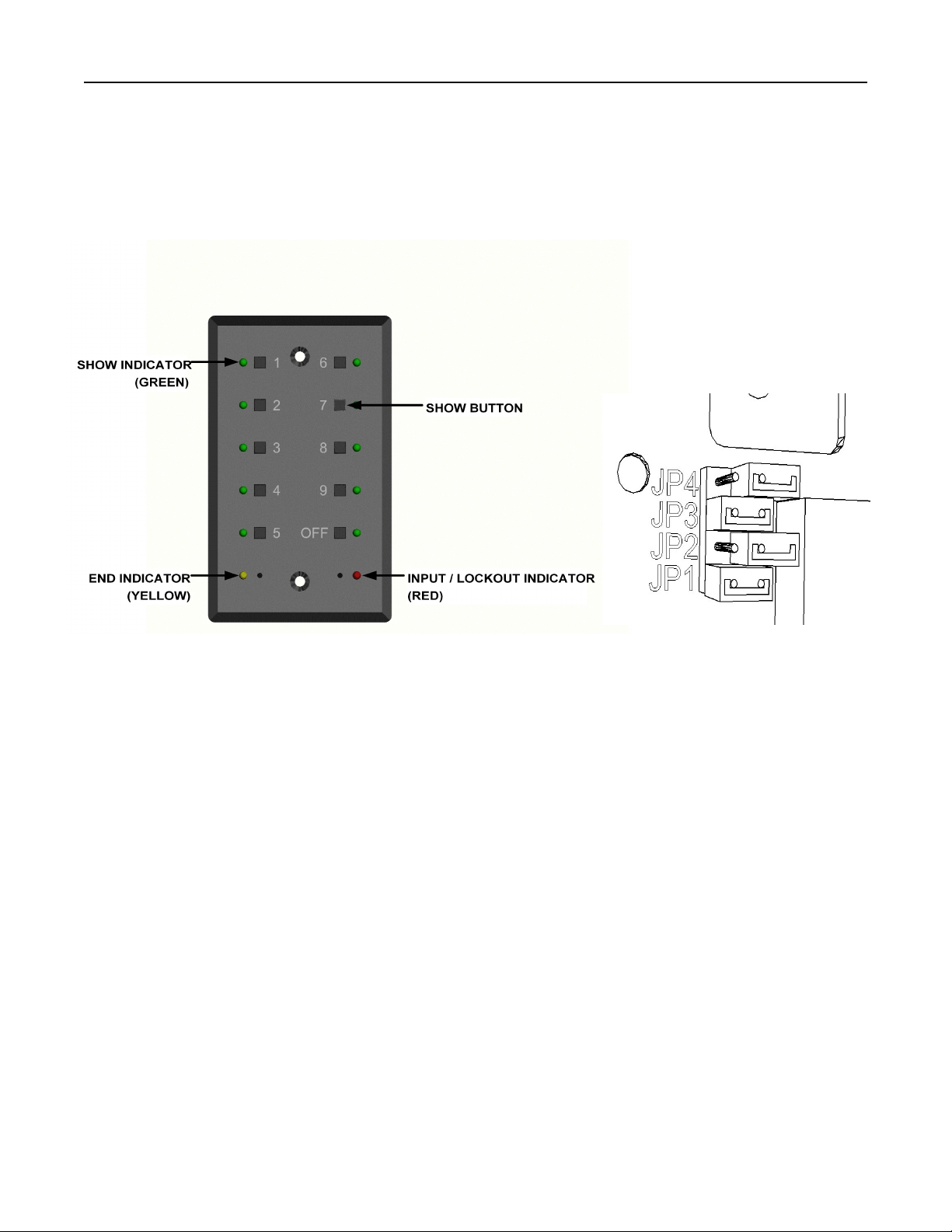
When a show is set to stop running at the END POINT (not looping) the behavior of the Rerun Rackmount
can be set up in two different ways. By default, a show stops at its END POINT and the Rerun Rackmount
continues to send the last levels of that show until a new show is selected. Each show can be set up to
stop sending DMX512 data entirely at the end of the show. Stopping DMX512 data at the end of the show
is enabled on show 10 by default and disabled on all other shows. By going off-line, many moving lights
and dimming systems will detect the loss of DMX512 and begin their shut down routines.
To alter the end-of-show behavior, do the following:
1. Start playing the show to be edited.
2. Pause the show at any point.
3. If it is not disabled already, disable looping for the show (Looping section above).
4. Press and hold the number 10 [SHOW] button. Hold the number 10 [SHOW] button for about five
seconds. While held, the remaining [SHOW LEDS] will indicate the status of other show and
system parameters. The number 2 [SHOW LED] indicates the status of the end-of-show output
option for that show. While continuing to hold the number 10 [SHOW] button, press the number
2 [SHOW] button to toggle the state of the option. When the number 2 [SHOW LED] is lit, the
Rerun Rackmount will stop DMX512 output at the end of the show. When the number 2 [SHOW
LED] is off, the Rerun Rackmount will continue sending DMX512 at the end of the show. Set the
end-of-show transmission option as desired.
5. Release the number 10 [SHOW] button.
6. Press the [PAUSE] button to save the new settings and to resume the show.
Note:
!The end-of-show behavior will only apply if the show has looping disabled.

Page 11 of 12
EDITING SHOW PARAMETERS (CONTINUED)
Software record lockout
The Rerun Rackmount has a software record lockout feature. When the software record lockout is
enabled, no shows can be recorded and no parameter data can be modified.
To alter the software record lockout status, do the following:
1. Start playing any show.
2. Pause the show at any point.
3. Press and hold the number 10 [SHOW] button. Hold the number 10 [SHOW] button for about five
seconds. While held, the remaining [SHOW LEDS] will indicate the status of other show and
system parameters. The number 1 [SHOW LED] indicates the status of the software record lockout
output option. While continuing to hold the number 10 [SHOW] button, press the number 1 [SHOW]
button to toggle the state of the option. When the number 1 [SHOW LED] is lit, the Rerun
Rackmount will not allow any show or parameter data to be changed. When the number 1 [SHOW
LED] is off, the Rerun Rackmount will allow changes to be made. Set the software record lockout
option as desired.
4. Release the number 10 [SHOW] button.
5. Press the [PAUSE] button to save the new settings and to resume the show.
Note:
!The software record lockout feature is a global system parameter. Although it can be accessed from any show,
there is only one record lockout state.
!By default, the software record lockout feature is disabled (recording enabled).
Front panel lockout
The front panel buttons on the Rerun Rackmount can be locked to prevent tampering with a running show.
The ability to lock out the front panel is disabled by default.
To enable or disable the ability to lock the front panel, do the following:
1. Start playing any show.
2. Pause the show at any point.
3. Press and hold the number 10 [SHOW] button. Hold the number 10 [SHOW] button for about five
seconds. While held, the remaining [SHOW LEDS] will indicate the status of other show and
system parameters. The number 4 [SHOW LED] indicates the status of the front panel lockout
output option. While continuing to hold the number 10 [SHOW] button, press the number 4 [SHOW]
button to toggle the state of the option. When the number 4 [SHOW LED] is lit, the Rerun
Rackmount will allow the front panel to be locked. When the number 4 [SHOW LED] is off, the
Rerun Rackmout will not allow the front panel to be locked. Set the front panel lockout enable
option as desired.
4. Release the number 10 [SHOW] button.
5. Press the [PAUSE] button to save the new settings and to resume the show.
Note:
!The front panel lockout enable feature is a global system parameter. Although it can be accessed from any show, there
is only one front panel lockout enable state.
!By default, the front panel cannot be locked.
!See the Front panel lockout section in the LOCKING THE FRONT PANEL section for operational details.

Page 12 of 12
EDITING SHOW PARAMETERS (CONTINUED)
Grand master
A grand master feature is available as a factory option. This feature allows the user to alter the overall level
output of the current show. The REWIND and FORWARD buttons are used to access this feature while
the show is running. The REWIND button raises the grand master and the FORWARD button lowers it.
The grand master feature (if enabled) only operates on universe 1. There is no facility for other universes
to process the grand master feature at this time. It is recommended that the grand master feature should
not be used in multi-universe Rerun DMX recorders.
Note:
!The grand master feature can only be enabled at the factory. It cannot be enabled in the field.
!The grand master feature is disabled by default.
!When enabled, the grand master feature does not alter the levels of the incoming DMX512 levels.
LIMITED MANUFACTURER’S WARRANTY
Products manufactured by Doug Fleenor Design (DFD) carry a five-year parts and labor warranty against
manufacturing defects. It is the customer's responsibility to return the product to DFD at the customer's
expense. If covered under warranty, DFD will repair the unit and pay for return ground shipping. If a trip
is necessary to the customer's site to solve a problem, the expenses of the trip must be paid by the
customer.
This warranty covers manufacturing defects. It does not cover damage due to abuse, misuse, negligence,
accident, alteration, or repair by other than by Doug Fleenor Design.
Most non-warranty repairs are made for a fixed $50.00 fee, plus shipping.
Doug Fleenor Design, Inc.
396 Corbett Canyon Road
Arroyo Grande, CA 93420
(805) 481-9599 voice and FAX
(888) 4-DMX512 toll free (888) 436-9512
web site: http://www.dfd.com
e-mail: info@dfd.com
This manual suits for next models
4
Table of contents
Other Doug Fleenor Design Recording Equipment manuals
Popular Recording Equipment manuals by other brands

Akai
Akai MPC Service manual

Dataq Instruments
Dataq Instruments DI-700 user manual

Klark Teknik
Klark Teknik VNET2-AES INTERFACE quick start guide

Hakko Electronics
Hakko Electronics B5211 manual

Phonak
Phonak Advanced Bionics Naida CI Q70 Fittings guide

Toft Audio Designs
Toft Audio Designs ATB series Console user manual