BACnet Gateway: Directions & Applications page 4 lighting controls
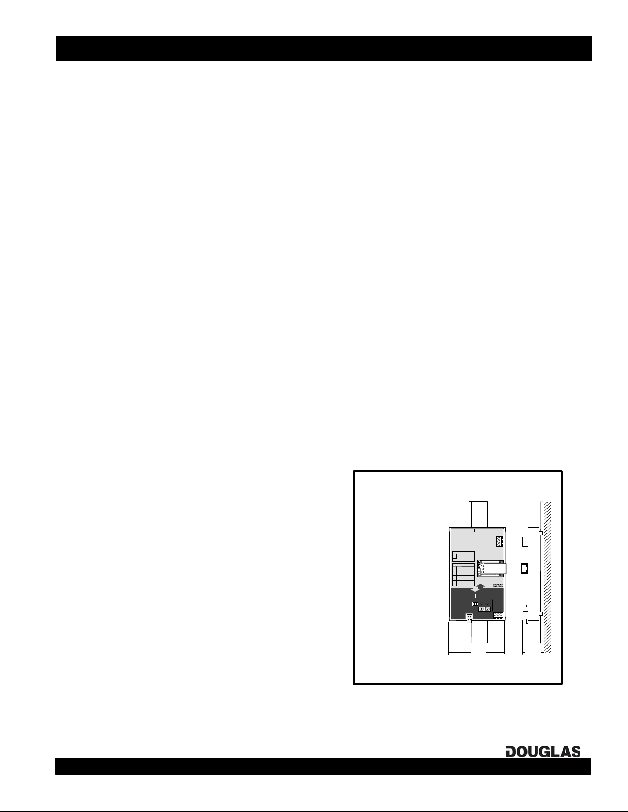
Installation: Factory-Assembled W-2000 Systems
INSTALLATION INSTRUCTIONS: PRE-ASSEMBLED DOUGLAS W-2000 SYSTEMS
1. Install the pre-assembled relay panels. Be sure that the panels are
located closely enough together so that the network line length
required to interconnect them does not exceed the specification
called out in the One-Line Diagram page of the drawings supplied
with the system.
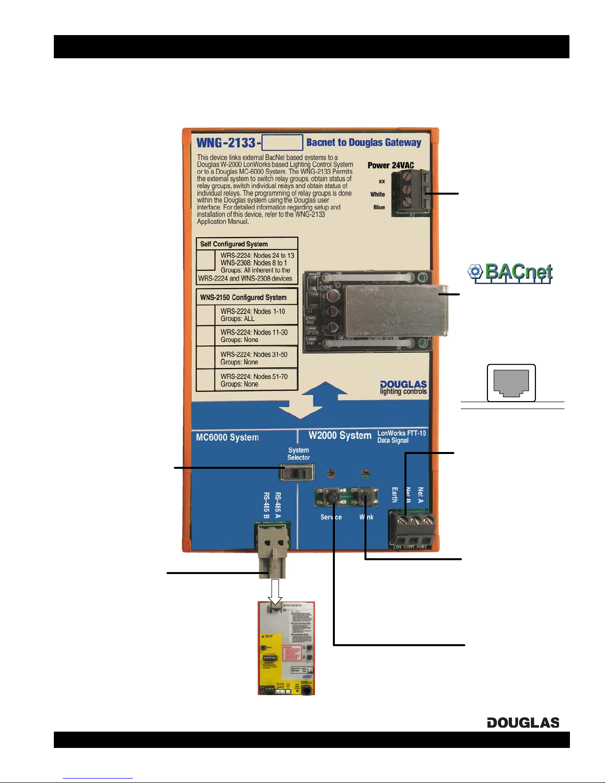
2. Make sure the Douglas network select setting and connnections
on the WNG-2133 BACnet Node are correct for a W-2000
System.
3. In each panel, connect the lighting loads to the output relays of
the scanner. You should make note of which load is connected
to each relay in the relay schedule for each panel.
4. In each panel, connect the group switching devices (switch or
timer) to the scanner group inputs. If you are connecting 24V
switching devices other than a default Douglas switch or time
clock, you will have to first configure their inputs. Use the
keyboard on the scanner, as detailed in the 'Scanner Input
Configuration' section on page 7 of this manual.
5. A maximum of 6 switching devices can be connected in parallel
to the same master input, with a maximum wire length of
2000'/600m if using 18 AWG wire.
6. Interconnect the WNX-2624 Network Nodes with the data signal
wire (shielded twisted pair in a single loop). Be sure to connect
them in the exact order shown in the One-Line Diagram in the
drawings supplied with the system.
7. Power the system up. LEDs will flash briefly on the scanners
and nodes. Make sure that the Digital Link LED is ON on each
scanner. If not, check the connnections and the node settings.
8. Determine which output relays are to be switched together as groups.
Different output relays from any scanners in the network can be
grouped together to be switched by the same group input. An output
relay can also be in more than one group.
9. (SELF-CONFIGURED SYSTEMS)
Use the keypad on each scanner to assign the output relays to each
group input:
9. (WNP-2150-CONFIGURED SYSTEMS)
Use the browser interface of the WNP-2150 Network Manager to
assign the output relays to each group input:
In most cases, a Douglas BACnet-accessible W-2000
system is assembled panel-by-panel and initially configured
at the factory.
For each panel in a pre-assembled system, it is necessary to
install the panel, check the basic network settings, connect
the switch inputs to the appropriate group inputs and
connect the outputs to the appropriate relays.
After this is done for all the panels in the network, the panels
are interconnected following the one-line diagram supplied
with the system. If not previously done at the factory,
outputs can be assigned to the group inputs of each relay
scanner once the panels are interconnected.
a) Go to the scanner with the group input to be programmed and
select that input by toggling the scanner's INPUT SELECT BUTTON.
b) Press the scanner's PROGRAM MODE BUTTON. This places the
entire network in Program mode. The Output LED for any output, on
any scanner, that is controlled by the input will be lit.
c) Add or remove an output relay on any scanner from the input by
toggling its OUTPUT BUTTON.
d) Press the NORMAL MODE BUTTON on the input's scanner to exit
the network from Program mode.
e) Repeat steps (a-d) for other inputs.
a) Connect computer with Internet Browser to WNP-2150 following
directions on label. Enter WNP-2150's IP address in browser's
address field to display Lighting Scheduling software.
b) List relay groups using the GROUPS/NEW Submenu.
c) Assign relays to groups using GROUPS/PROGRAM RELAYS
Submenu. Go panel-by panel untill all relays have been added to all
of the groups.
d) Assign groups to inputs using GROUPS/PROGRAM INPUTS
Submenu. For each input, also assign the action triggered and
hardware type.
e) Repeat steps (a-d) for other inputs.