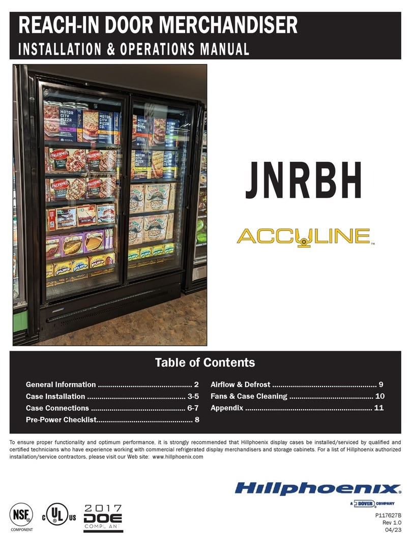
Dover Hillphoenix CNZLA User manual

04/22
Technical References ................................................. 2-7
General Information ........................................................8
Installation ................................................................ 9-15
Case Connections ...................................................16-19
Lighting & Power Supplies......................................20-22
Pre-Power Checklist .................................................... 23
Airow & Defrost .......................................................... 24
Case Cleaning .........................................................25-27
Troubleshooting ......................................................28-29
Safety Devices & Service .......................................30-31
Parts Ordering .............................................................. 32
Appendices
Table of Contents
To ensure proper functionality and optimum performance, it is STRONGLY recommended that Hillphoenix specialty cases be installed/serviced by qualied tech-
nicians who have experience working with commercial refrigerated display merchandisers and storage cabinets. For a list of Hillphoenix-authorized installation/
service contractors, please visit our website at www.hillphoenix.com.
CNZLA/CNEZLA
(R-290)
SINGLE-DECK MERCHANDISER
INSTALLATION & OPERATIONS MANUAL

ii

Important
DANGER
▲
�
Indicates an immediate threat of death or seri-
ous injury if all instructions are not followed
carefully.
At Hillphoenix®, the safety of our customers and employees, as well as the ongo-
ing performance of our products, are top priorities. To that end, we include impor-
tant warning messages in all Hillphoenix installation and operations handbooks,
accompanied by an alert symbol paired with the word "DANGER", "WARNING", or
"CAUTION".
All warning messages will inform you of the potential hazard; how to reduce the
risk of case damage, personal injury or death; and what may happen if the in-
structions are not properly followed.
This manual must be stored near the display case where it can be easily consult-
ed. If this manual does not provide the information you require please contact
Hillphoenix for more information.
WARNING
Indicates a potential threat of death or serious
injury if all instructions are not followed care-
fully.
▲
�
CAUTION
Indicates that failure to properly follow instruc-
tions may result in case damage.
▲
�
iii

Revision History
• new manual format_04/22
iv

TECHNICAL REFERENCE
ENGINEERED FOR STORES WITH AMBIENT
CONDITIONS NOT TO EXCEED 75° AND 55%
RELATIVE HUMIDITY. DUE TO ENGINEERING
IMPROVEMENTS SPECIFICATIONS MAY CHANGE
WITHOUT NOTICE. ALL MEASUREMENTS ARE
TAKEN PER ASHRAE-72 SPECIFICATIONS.
HILLPHOENIX REFRIGERATED DISPLAY CASES
FOR SALE IN THE UNITED STATES MEET OR EXCEED
DEPARTMENT OF ENERGY 2017 REQUIREMENTS.
NUMBERS ARE BASED ON STANDARD CASE SIZES.
CONSULT ENGINEERING.
CNZLA
4', 7', & 8' Coldwall R290 Merchandiser
Beverage/Dairy/Meat/Frozen Food/Ice Cream
CNZLA
SHIPPING WEIGHT
Case Weight
CNZLA ----
Rev. Date Rev. # Rev. Title
08-10-22 0 NEW STANDARD
GENERAL NOTES:
• "---" indicates that feature is not an option on this case model and/or the data is not yet available.
2

TECHNICAL REFERENCE
ENGINEERED FOR STORES WITH AMBIENT
CONDITIONS NOT TO EXCEED 75° AND 55%
RELATIVE HUMIDITY. DUE TO ENGINEERING
IMPROVEMENTS SPECIFICATIONS MAY CHANGE
WITHOUT NOTICE. ALL MEASUREMENTS ARE
TAKEN PER ASHRAE-72 SPECIFICATIONS.
HILLPHOENIX REFRIGERATED DISPLAY CASES
FOR SALE IN THE UNITED STATES MEET OR EXCEED
DEPARTMENT OF ENERGY 2017 REQUIREMENTS.
NUMBERS ARE BASED ON STANDARD CASE SIZES.
CONSULT ENGINEERING.
CNZLA
4', 7', & 8' Coldwall R290 Merchandiser
Beverage/Dairy/Meat/Frozen Food/Ice Cream
CNZLA
GUIDELINES AND CONTROL SETTINGS
Application
Set Point
St (°F)
Defrost
Termination
Temp (°F)
Defrost
Interval (hr)
Fail Safe
(Min)
Dairy 39 50 24 10
Meat 36 50 24 10
Frozen Food 5 50 24 10
Ice Cream - 9 50 24 10
Rev. Date Rev. # Rev. Title
08-10-22 0 NEW STANDARD
NOTES:
• "---" indicates that feature is not an option on this case model and/or the data is not yet available.
• Minimum clearance for single unit installation = 3.9" (100mm).
• Minimum clearance for island arrangement: Rear = 5.5"; Side = 0".
• NEMA L5-15P locking plug available upon request.
SYSTEM REQUIREMENTS
Case
Length Overall Size Volts
Frequency
(Hz) Phase Plug* TLA MCA MOP
Product
Weight (lbs)
4' 56.7" x 34.5" x 36.6" 120 50/60 1 NEMA 5-15 5.6 6.4 15 230
7' 84.8" x 34.5" x 36.6" 120 50/60 1 NEMA 5-15 8.4 12.9 15 297
8' 98.7" x 34.5" x 36.6" 120 50/60 1 NEMA 5-15 8.4 13.7 15 363
CONDENSING UNIT DATA
Case
Length Volts Phase
Hysteresis
(Min)
Max
Capacity (hp)
Running Load
Amps (RLA)
Locked Rotor
Amps (LRA) Refrigerant
Refrigerant
Charge (grams)
Noise Limit
(dBA)
4' 120 1 2 0.75 7 Electronic Cut Off R290 120 60
7' 120 1 2 1.25 7 Electronic Cut Off R290 140 60
8' 120 1 2 1.25 7 Electronic Cut Off R290 150 60
24hr Energy
Case
Length Application (kWh)
4' Dairy, Meat 1.3
4' Frozen Food, Ice Cream 2.7
7' Dairy, Meat 2.0
7' Frozen Food, Ice Cream 3.6
8' Dairy, Meat 2.5
8' Frozen Food, Ice Cream 4.1
LIGHTING DATA
Case
Length
Lights per
case Amps Watts
4' 1 0.08 10
7' 1 0.11 13.5
8' 1 0.12 15
3

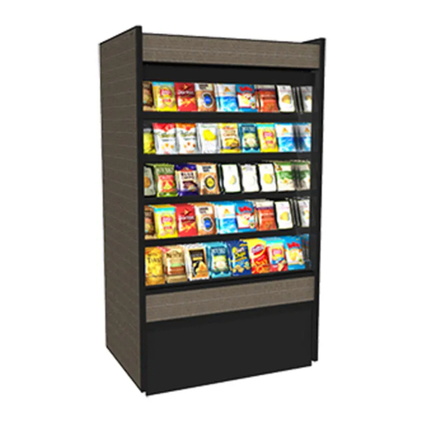
TECHNICAL REFERENCE
98 3/8" [249.9 cm]
33 7/8" [86.1 cm]
56 3/4" [144.1 cm]
84 7/8" [215.7 cm]
36 3/8" [92.4 cm]
33 7/8" [86.1 cm]
33 3/4" [85.9 cm]
32 1/4" [82.1 cm]
37 3/4" [95.8 cm]
30 3/4" [78.0 cm]
23 3/8" [59.4 cm]
INTERIOR HEIGHT
19 3/4" [50.1 cm]
LOAD LIMIT
ENGINEERED FOR STORES WITH AMBIENT
CONDITIONS NOT TO EXCEED 75° AND 55%
RELATIVE HUMIDITY. DUE TO ENGINEERING
IMPROVEMENTS SPECIFICATIONS MAY CHANGE
WITHOUT NOTICE. ALL MEASUREMENTS ARE
TAKEN PER ASHRAE-72 SPECIFICATIONS.
HILLPHOENIX REFRIGERATED DISPLAY CASES
FOR SALE IN THE UNITED STATES MEET OR EXCEED
DEPARTMENT OF ENERGY 2017 REQUIREMENTS.
NUMBERS ARE BASED ON STANDARD CASE SIZES.
CONSULT ENGINEERING.
CNZLA
4', 7', & 8' Coldwall R290 Merchandiser
Beverage/Dairy/Meat/Frozen Food/Ice Cream
CNZLA
Rev. Date Rev. # Rev. Title
08-10-22 0 NEW STANDARD
4

TECHNICAL REFERENCE
ENGINEERED FOR STORES WITH AMBIENT
CONDITIONS NOT TO EXCEED 75° AND 55%
RELATIVE HUMIDITY. DUE TO ENGINEERING
IMPROVEMENTS SPECIFICATIONS MAY CHANGE
WITHOUT NOTICE. ALL MEASUREMENTS ARE
TAKEN PER ASHRAE-72 SPECIFICATIONS.
HILLPHOENIX REFRIGERATED DISPLAY CASES
FOR SALE IN THE UNITED STATES MEET OR EXCEED
DEPARTMENT OF ENERGY 2017 REQUIREMENTS.
NUMBERS ARE BASED ON STANDARD CASE SIZES.
CONSULT ENGINEERING.
CNEZLA
Endcap Case Coldwall R290 Merchandiser
Beverage/Dairy/Meat/Frozen Food/Ice Cream
CNEZLA
SHIPPING WEIGHT
Case Weight
CNEZLA ----
Rev. Date Rev. # Rev. Title
08-10-22 0 NEW STANDARD
GENERAL NOTES:
• "---" indicates that feature is not an option on this case model and/or the data is not yet available.
5

ENGINEERED FOR STORES WITH AMBIENT
CONDITIONS NOT TO EXCEED 75° AND 55%
RELATIVE HUMIDITY. DUE TO ENGINEERING
IMPROVEMENTS SPECIFICATIONS MAY CHANGE
WITHOUT NOTICE. ALL MEASUREMENTS ARE
TAKEN PER ASHRAE-72 SPECIFICATIONS.
HILLPHOENIX REFRIGERATED DISPLAY CASES
FOR SALE IN THE UNITED STATES MEET OR EXCEED
DEPARTMENT OF ENERGY 2017 REQUIREMENTS.
NUMBERS ARE BASED ON STANDARD CASE SIZES.
CONSULT ENGINEERING.
CNEZLA
Endcap Case Coldwall R290 Merchandiser
Beverage/Dairy/Meat/Frozen Food/Ice Cream
CNEZLA
Rev. Date Rev. # Rev. Title
08-10-22 0 NEW STANDARD
GUIDELINES AND CONTROL SETTINGS
Application
Set Point
St (°F)
Defrost
Termination
Temp (°F)
Defrost
Interval (hr)
Fail Safe
(Min)
Dairy 39 50 24 10
Meat 36 50 24 10
Frozen Food 5 50 24 10
Ice Cream -9 50 24 10
NOTES:
• "---" indicates that feature is not an option on this case model and/or the data is not yet available.
• Minimum clearance for single unit installation = 3.9" (100mm).
• Minimum clearance for island arrangement: Rear = 5.5"; Side = 0".
• NEMA L5-15P locking plug available upon request.
SYSTEM REQUIREMENTS
Case
Length Overall Size Volts
Frequency
(Hz) Phase Plug* TLA MCA MOP
Product
Weight (lbs)
6' 73.6" x 34.5" x 36.6" 120 50/60 1 NEMA 5-15 5.6 7.4 15 262
24hr Energy
Case
Length Application (kWh)
6' Dairy, Meat 1.6
6' Frozen Food, Ice Cream 3.1
LIGHTING DATA
Case
Length
Lights per
case Amps Watts
6' 1 0.10 13
CONDENSING UNIT DATA
Case
Length Volts Phase
Hysteresis
(Min)
Max Capacity
(hp)
Running Load
Amps (RLA)
Locked Rotor
Amps (LRA) Refrigerant
Refrigerant
Charge (grams)
Noise Limit
(dBA)
6' 120 1 2 0.75 7 Electronic Cut Off R290 132 60
TECHNICAL REFERENCE
6

73 1/2" [186.8 cm]
33 7/8" [86.0 cm]
36 3/8" [92.4 cm]
33 7/8" [86.2 cm]
37 5/8" [95.7 cm]
30 3/4" [78.0 cm]
23 3/8" [59.4 cm]
INTERIOR HEIGHT
19 3/4" [50.1 cm]
33 3/4" [85.8 cm]
30 7/8" [78.6 cm]
LOAD LIMIT
ENGINEERED FOR STORES WITH AMBIENT
CONDITIONS NOT TO EXCEED 75° AND 55%
RELATIVE HUMIDITY. DUE TO ENGINEERING
IMPROVEMENTS SPECIFICATIONS MAY CHANGE
WITHOUT NOTICE. ALL MEASUREMENTS ARE
TAKEN PER ASHRAE-72 SPECIFICATIONS.
HILLPHOENIX REFRIGERATED DISPLAY CASES
FOR SALE IN THE UNITED STATES MEET OR EXCEED
DEPARTMENT OF ENERGY 2017 REQUIREMENTS.
NUMBERS ARE BASED ON STANDARD CASE SIZES.
CONSULT ENGINEERING.
CNEZLA
Endcap Case Coldwall R290 Merchandiser
Beverage/Dairy/Meat/Frozen Food/Ice Cream
CNEZLA
Rev. Date Rev. # Rev. Title
08-10-22 0 NEW STANDARD
TECHNICAL REFERENCE
7

Thank you for choosing Hillphoenix for your food merchandising needs. This handbook contains important technical infor-
mation and will assist you with the installation and operation of your new Hillphoenix cases. By closely following the instruc-
tions, you can expect peak performance; attractive fit and finish; and long case life.
We are always interested in your suggestions for improvements (e.g. case design, technical documents, etc.). Please feel
free to contact our Marketing Services group at the number listed below. Thank you for choosing Hillphoenix, and we wish
you the very best in outstanding food merchandising.
CASE DESCRIPTION
This manual specifically covers the CNZLA and CNEZLA
(R-290) deli, meat, frozen food and ice cream application self-
service single-deck merchandiser with sliding doors.
STORE CONDITIONS
Hillphoenix cases are designed to operate in an air-condi-
tioned store that maintains a 75°F (24°C) store temperature
and 55% (max) relative humidity (ASHRAE conditions). Case
operation will be adversely affected by exposure to excessively
high ambient temperatures and/or humidity.
REFRIGERATION SYSTEM OPERATION
Air-cooled condensing units require adequate ventilation for
efficient performance.
THIS UNIT CONTAINS R-290 FLAMMABLE REFRIGERANT. USE
CAUTION WHEN HANDLING, MOVING OR SERVICING THE DISPLAY
CASE. AVOID DAMAGING THE REFRIGERANT TUBING WHICH COULD
INCREASE THE RISK OF A LEAK.
SHIPPING CASES
Transportation companies assume all liability from the time a
shipment is received by them until the time it is delivered to
the consumer. Our liability ceases at the time of shipment.
RECEIVING CASES
Examine fixtures carefully and in the event of shipping dam-
age and/or shortages, please contact the Service Parts
Department at the number listed below.
CASE DAMAGE
Claims for obvious damage must be 1) noted on either the
freight bill or the express receipt and 2) signed by the carrier's
agent; otherwise, the carrier may refuse the claim. If damage
becomes apparent after the equipment is unpacked, retain all
packing materials and submit a written request to the carrier
for inspection within 14 days of receipt of the equipment.
Failure to follow this procedure will result in refusal by the
carrier to honor any claims with a consequent loss to the
consumer.
If a UPS shipment has been damaged, retain the damaged
material, the carton and notify us at once. We will file a claim.
LOST/MISSING ITEMS
Equipment has been carefully inspected to insure the highest
level of quality. Any claim for lost/missing items must be
made to Hillphoenix within 48 hours of receipt of the equip-
ment. When making a claim please use the number listed
below.
SERVICE PARTS & TECHNICAL SUPPORT
For service parts questions regarding our cases, please
contact our Service Parts Department at 1-844-HPX-PART
(1-844-479-7278) or [email protected]
(warranty claim group) and dfr-orderparts@doverfoodretail.
com (non-warranty claim group). For parts choose your lan-
guage, then select option 1 for Case Division Parts.
For technical questions regarding our cases, please contact
our Technical Support Department at 1-833-280-5714. For
Technical Support select option 2, then once in that menu,
select option 1 for the Main Case Division.
CONTACTING THE FACTORY
If you need to contact Hillphoenix regarding a specific fixture,
be certain that you have both the case model number and
serial number. (This information can be found on the data tag,
located at the top-left interior, rear exterior panel or interior
rear lower storage of the case. Location may vary based on
case design.)
Hillphoenix
1925 Ruffin Mill Rd
Colonial Heights, VA 23834
Website: www.hillphoenix.com
GENERAL INFORMATION
8

UNITIZATION ASSEMBLY KITS
CASE INSTALLATION
CLOSE OFF PANEL KIT (GRAY 4')
HPX P/N ITEM QNTY DESCRIPTION COLOR
P116702CGY
4.1 10 Flange Hexagon Bolt, M6x16 - - -
3.3 2 Front Kickplate Linking Plate, IHF-0D2209PB Gray
1.5 1 Cover Plate, IHF-D1509PB Gray
*1.3 2 Middle Cover Plate, IHFD2209PB Gray
1.4 1 Case Connecting Cover, IHF-D2209PB Gray
CLOSE OFF PANEL KIT (WHITE 6' END)
HPX P/N ITEM QNTY DESCRIPTION COLOR
P116707CGY - - - 5 Flange Hexagon Bolt, M6x16 - - -
1.1 1 Supporting Column, IHF-D2209PB Gray
CLOSE OFF PANEL KIT (GRAY 7')
HPX P/N ITEM QNTY DESCRIPTION COLOR
P116710FGY
4.1 10 Flange Hexagon Bolt, M6x16 - - -
3.3 2 Front Kickplate Linking Plate, IHF-D2209PB Gray
1.2 1 Cover Plate, IHF-D2209PB Gray
*1.3 2 Middle Cover Plate, IHF-D2209PB Gray
1.4 1 Case Connecting Cover, IHF-D2209PB Gray
CLOSE OFF PANEL KIT (GRAY 8')
HPX P/N ITEM QNTY DESCRIPTION COLOR
P116713MGY
4.1 10 Flange Hexagon Bolt, M6x16 - - -
3.3 2 Front Kickplate Linking Plate, IHF-D2209PB Gray
1.6 1 Cover Plate, IHF-D2509PB Gray
*1.3 2 Middle Cover Plate, IHF-D2209PB Gray
1.4 1 Case Connecting Cover, IHF-D2209PB Gray
SIDE CLOSE OFF KIT (GRAY/GRAY)
HPX P/N ITEM QNTY DESCRIPTION COLOR
P116714HGY
3.2 1 Side Kickplate IHF-D2209PB Gray
1.1 1 Supporting Column, IHF-D2209PB Gray
4.2 5 Flange Hexagon Bolt, M6x16 - - -
SIDE CLOSE OFF KIT (GRAY/WHITE)
HPX P/N ITEM QNTY DESCRIPTION COLOR
P116714HWH
3.2 1 Side Kickplate, IHF-D2209PB Gray
1.1 1 Supporting Column, IHF-D2209PB White
4.2 5 Flange Hexagon Bolt, M6x16 - - -
REFERENCE DIAGRAMS ON FOLLOWING PAGES (CONT'D)
* See (Fig. 11) for a detail of the connecting plate.
9

CASE INSTALLATION
FRONT KICKPLATE
LINKING PLATE
**SIDE KICKPLATE
(END CAP)
**CORNER COVER PLATE
(END CAP)
**FRONT KICKPLATE
SIDE KICKPLATE
**FRONT KICKPLATE
(END CAP)
**PRICE PLATE COVER PLATE
MIDDLE COVER PLATE
SUPPORTING COLUMN
**PRICE TAG MOLDING
BACK-TO-BACK ASSEMBLY (DIAGRAM 1)
BACK-TO-BACK ASSEMBLY W/ END CAP ASSEMBLY (DIAGRAM 2)
** These parts ship with the case.
* See (Fig. 11) for a detail of the connecting plate.
10

FLOOR PREP
1. Ask the general contractor if your current copy of the build-
ing dimensions are the most recently issued. Also, ask for
the points of reference from which you should take dimen-
sions to locate the cases.
2. Using chalk lines or a laser transit, mark the oor where
the cases are to be located for the entire lineup. The lines
should coincide with the outside edges of the case feet.
3. Move case as close as possible to its permanent location.
Remove all crating and shipping braces above the ship-
ping pallet. Loosen the plastic dust cover from the pallet,
but leave cover over the case to protect it while removing
the case from the pallet.
4. The power cord shipping brace can be removed with a
screw gun if attached to the pallet. Otherwise, the power
cord is attached to the case with a zip tie and needs to be
removed carefully.
5. Carefully, if horizontal supports, lift case up and off the
pallet. Remove dust cover. Check for loose components
in the packaging. Do not dispose of of loose components.
If it cannot be determined where the loose components
belong, call Hillphoenix technical support. (Hillphoenix
self-contained display cases are sometimes designed with
casters. In most situations, one or two persons can easily
move the case into position.) If there are casters simply
roll them on to the store oor to the proper staging area.
First remove all crating then all sled runner, caster, and/or
power cord shipping braces. (Dependent on case design.)
6. Leveling is necessary to ensure proper operation of the
refrigeration system and drainage of the condensate.
Locate the highest point on the positioning lines as a
reference for determining levelers. A laser transit is rec-
LOCATION
This refrigerated display case has been designed for displaying
and storing perishable food product. It is engineered for air-
conditioned stores with a maximum ambient of 75°F and 55%
relative humidity.
When selecting the location for placement of this case, avoid
the following conditions:
Excessive Air Movement
1. Doors
2. Air-conditioned vents
3. Other air sources
Excessive Heat
1. Windows
2. Sun
3. Flood lamps 8 feet or less from the product
4. Other heat sources
ommended for precision and requires just one person.
When in nal position level adjustable feet (Fig. 1 & 2) as
needed so that the casters are not engaged to the oor.
To do so, rst rotate the nut at the adjustable feet coun-
terclockwise. Turn feet until engaged to the oor and the
casters no longer make contact to the ground.
Fig. 1 Vertical supports
Fig. 2 Adjustable leveling feet and casters
7. (CASTERS/BULLET LEGS) If necessary, attach two brack-
ets at two separate corners of the case (Fig. 3) and fasten
to the oor with concrete anchors. Prior to attaching
brackets be sure to turn the power OFF to the case and
unplug power cord.
CAUTION
Failure to properly level the case could result in
lack of proper condensation drainage leading to
failure of the unit.
▲
�
CASE INSTALLATION
SUPPORTS
Fig. 3 Seismic anchoring (brackets)
BRACKETBRACKET
8. The brackets need to be afxed in the exact locations
specied here (below) due to the R-290 case design
components inside the case. Be sure that at least two
11

with case joining. Keep all loose items as they will be used
later in the installation process.
2. Move the case into position. The case has a two lane pal-
let with connecting strips and enforcement steel panels.
3. Use a (philips) to remove the screws on each of the steel
panels at each corner of the pallet. After the steel panels
are removed pull away the connecting strips (Fig. 4) at
each palet side. Insert pallet jack or fork lift at the gap left
by the connecting strips, turn up the case and take away
the two side/end pallets. Repeat as needed.
CAUTION
These cases are not designed for excessive
external weight. Do not walk on top or inside
of cases. Doing so may result in case damage
and/or personal injury.
▲
�
LINE-UP & INSTALLATION
Single Case
1. Remove any loose items from the cases that may interfere
WARNING
Be certain that your hands and feet are out of
the way before lowering the case. Failure to do
so may result in serious injury.
▲
�
CAUTION
Locate the horizontal or vertical (caster) sup-
ports under unit before removing from pallet.
Failure to do so will damage the nished metal
if correct lift points are not identied prior to
removal.
▲
�
CASE INSTALLATION
Fig. 4 Remove connecting strip
STEEL PANELSTEEL PANEL
CONNECTING STRIPCONNECTING STRIP
DANGER
FLAMMABLE
DANGER - Risk of Fire or Explosion. Flammable
Refrigerant Used. Do Not Use Mechanical De-
vices To Defrost Refrigerator. Do Not Puncture
Refrigerant Tubing.
▲
�
DANGER
▲
�
SHOCK HAZARD
Always disconnect power to case when cleaning,
servicing or conguring components. Failure to
do so may result in serious injury or death.
Fig. 5 Front kickplate install
brackets are used, one at each corner.
4. Once the case is properly placed check the vertical plumb
of the case by placing a bubble level on the rear wall. For
the horizontal level, repeat this process after placing the
bubble level on the front sill.
5. Install the bumper, if applicable, into pre-attached bumper
track and snap into place. (Most self-contained cases ship
with bumper pre-installed.)
6. Install the kickplate xing plate according to the position
shown in the gure, and use the screws delivered with the
product, with the specications of ST4.2 x 13.
7. Install the front kickplate (Fig 5). The specication of the
screw is the same as that mentioned above. Fix the right
side rst.
12

CAUTION
Do not obstruct ventilation around the base of
the display case condensing unit. Obstructing
could cause the case to not operate correctly
and failure to maintain product temperatures.
▲
�
Multi-Case
1. Follow the single-case installation instructions 1 - 5 then
position the next case in the line-up approximately 3’
away.
2. Due to congestion of the warm exhaust air (heat accu-
mulation). The front, rear and undercase air vents of the
unit must not be covered for island arrangement.
3. An end case will butt against the ends of the straight
cases with a 0" gap. Note: Exhaust on side of end cases.
a) The exhaust air must be able to escape freely at
the backside of the unit.
b) Minimum distance for single unit installation
All Around = 3.9 in
c) Minimum distance for island arrangement
A = 0 in B = 5.5 in
4. Install the screws supplied at the rear of the case with
the equipment in the frame selected part of the diagram
(Fig. 7). The bolt specication is m6 x 16. The screws don't
need to be tightened for the time being.
CASE INSTALLATION
Fig. 7 Frame screw locations at rear of case
Fig. 8 Insert columns onto screws
Fig. 9 Back-to-back column connection
6. Place the showcase back-to-back, lift the column, and
connect the two cases together (Fig. 9).
7. Place the cover plate at the middle of the two cases, as
shown here (Fig. 10). Hardware is not required for this
step. Note: Do not merchandise on top of the cover plate
as this will restrict the air exhaust.
8. Install the side skirting board (Fig. 6).
Fig. 6 Side skirting board corner connections 5. Insert the column (Fig. 8) into the screw installation posi-
tion, one on the left and one on the right.
9. Use the front kickplate linking plate to x the front and
side kickplate.
Fig. 10 Placing cover plate
13

CASE INSTALLATION
Fig. 15 Side skirting board corner connections
Fig. 16 End cap front and corner kickplate connections
Fig. 17 Kickplate linking plate
Fig. 14 Front kickplate install
Fig. 11 Connecting plate for line-up
Fig. 12 Middle cover plate
Fig. 13 Kickplate fixing plate
8. If more than two cases need to be spliced in a line-up,
install the connecting plate according to the position (Fig.
11) after the two cases are placed.
end of the side skirting board kickplate (Fig. 14).
13. If there is an end cap case, x the front and corner kick-
plates together with screws (Fig. 16).
MIDDLE COVER PLATEMIDDLE COVER PLATE
14. Use the front kickplate linking plate to x the front and
side kickplate (Fig. 17).
9. Repeat steps for case splicing as needed and put the
middle cover plate down in the middle when ready (Fig.
12).
10. Install the kickplate xing plate according to the position
(Fig. 13) and use the screws delivered with the product,
with the specications of ST4.2 x 13.
11. Install the front kickplate with the xing plates at the top
of each two double cutouts depicted (Fig. 14). The speci-
cation of the screw is the same as that mentioned above.
Fix the right side rst.
12. Install the side skirting board at each connecting corner
(Fig. 15). Two screws at each corner. Note: Pre-install the
corner kickplate. If the adjoining case is an end case be
sure to next attach the corner kickplates (Fig. 16) to the 15. If there are more than two groups of cases that need to be
14

CASE INSTALLATION
CAUTION
Installation of 3rd-party materials may result in
diminished case performance.
▲
�
WIRE RACK
POSITION
HEIGHT OF RACK
FROM TANK BOTTOM
"A"
MERCHANDISING HEIGHT
RACK TO LOAD LIMIT LINE
"B"
Base (Bottom) 1-13/16" 18-5/16"
2nd Height 7-1/4" 12-7/8"
3rd Height 12" 8-1/8"
4th Height 17" 3-1/8"
Fig. 18 Adjustable wire racks and zip ties
Adjustable wire racks
The wire racks inside of the case(s) have four available heights
when including the base. First cut the zip ties holding the
DO NOT USEDO NOT USE
3RD3RD
2ND2ND
1ST1ST
BASEBASE
racks in place for shipping, then adjust the level of the wire
rack by using the side racks for placement (Fig. 18).
Note: Do not use the highest available point (Fig. 18) as this
height exceeds the load limit line for product.
ADJUSTABLE WIRE WRACK POSITIONS
spliced in a line-up, install the kickplate linking plate after
the front skirting board is xed.
16. Repeat steps of this sequence for all remaining cases. Be
certain to properly level all cases.
17. Install the price tag molding using double sided sticky
tape. Do not use hardware to install the tag molding as
this will interfere with the assembly of the center cover
panel.
15

ELECTRICAL
This case has a NEMA 5-15P plug (locking NEMA-15P plug
when applicable) that will need to be connected. Note: The
locking NEMA L5-15P plug can replace the standard NEMA
5-15P plug via the connector disconnect that is found in the
condensing unit compartment on the customer right hand
side of the case.
The case must be grounded. For more detailed electrical wir-
ing information (see Appendix A1).
Power Cord Locking L5-15P
Prior to plugging in and starting up the case always check the
data tag located on the outside back panel of the case, as well
as the voltage label found on the main power cord (if applica-
ble) which can be found at the rear base panel. Note: Check
that the voltage of the receptacle you are going to use for
power and the voltage required for the case match.
CAUTION
Be certain that all electrical connections are
compliant with local codes.
▲
�
CAUTION
Prior to plugging in and starting up the case.
Be certain that the voltage of the receptacle you
are going to use and the voltage required for the
case match. Failure to do so may result in case/
system damage.
▲
�
REFRIGERATION & COMPRESSOR COMPARTMENT
A bottom mounted compressor compartment (Fig. 21) can be
accessed by removing the lower rear panel. See Appendices
for full instructions on how to program the Dixell electronic
controller.
DANGER
CAUTION, RISK OF ELECTRIC SHOCK. If the
cord or plug becomes damaged, replace only
with a cord and plug of the same type.
▲
�
DANGER
CAUTION, RISK OF ELECTRIC SHOCK. Prior to
replacing the power cord and plug, be sure to
DISCONNECT POWER WITH THE MAIN PANEL
BREAKER to the case, before proceeding.
▲
�
Cord Replacement (5-15P to L5-15P)
Prior to replacing the power cord and plug, be sure to
DISCONNECT POWER to the case before proceeding. The
power can be disconnected at the main panel breaker in
the building. Just turning OFF the case with the main power
switch will NOT disconnect power coming to the case. Note:
The front control panel has a clear cover to help protect
against accidental access to switches. The controls can be
accessed by use of a tool put through the provided holes in
the cover.
To replace the standard 5-15P cord with the locking cord
L5-15P in the eld it is a quick disconnect of the connector
and ground terminal (Fig. 20) within the CDU compartment;
accessed from the rear air grill.
Fig. 19 Front panel grill & power switch
Fig. 20 Connector and ground terminal
FRONT GRILL
MAIN POWER SWITCH
Fig. 21 Compressor compartment
CASE CONNECTIONS
16

Fig. 22 Temperature probe connections
DANGER
When carrying out maintenance tasks inside the
refrigerated case or compressor compartment,
it is essential to disconnect the power source to
the case from the main power.
▲
�
DANGER
ALWAYS CHECK THE THERMOSTAT CURRENT
RATING. It may have a limited current, as low
as 2A. If necessary protect digital thermostat
contacts with a contractor.
▲
�
Fig. 23 Front panel power and light switch
LIGHT SWITCH
MAIN POWER SWITCH
CAUTION
Be sure to remove all Styrofoam shipping blocks
from piping and refrigerant lines. Failure to do
so may result in case damage.
▲
�
Electronic Cutoff
The CNZLA/CNEZLA compressors have an electronic cutoff
mechanism such that the LRA (Locked Rotor Amps) has zero
(0) amp draw after 4 seconds when the rotor becomes locked.
Power Supply & Light Switch
1. After the main power cord located at the base panel of the
case is plugged in and the power switch (Fig. 23) ipped
to ON the case should begin normal operations.
2. After establishing power the light control switch (Fig. 23)
(if applicable) located on the exterior front panel can be
ipped to the ON position. The case should now be fully
operational and all lights functioning when in the ON posi-
tion (if applicable).
3. Note: The front control panel has a clear cover to help
protect against accidental access to switches. The con-
trols can be accessed by use of a tool put through the
provided holes in the cover.
Temperature Probe Connections
1. The top probe is for defrost temperature and the bottom
probe is the case temperature (Fig. 22).
Access locations and/or R-290 compartment congurations
will vary based on case design. See page 18 for a compressor
compartment diagram.
CASE CONNECTIONS
17
This manual suits for next models
1
Table of contents
Other Dover Merchandiser manuals