DHG07-48/42 small cell power user manual<A>
5
Content
1. System Overview................................................................................................................................................ 7
1.1 System features............................................................................................................................................ 7
1.2 Main purpose and scope of application ....................................................................................................... 8
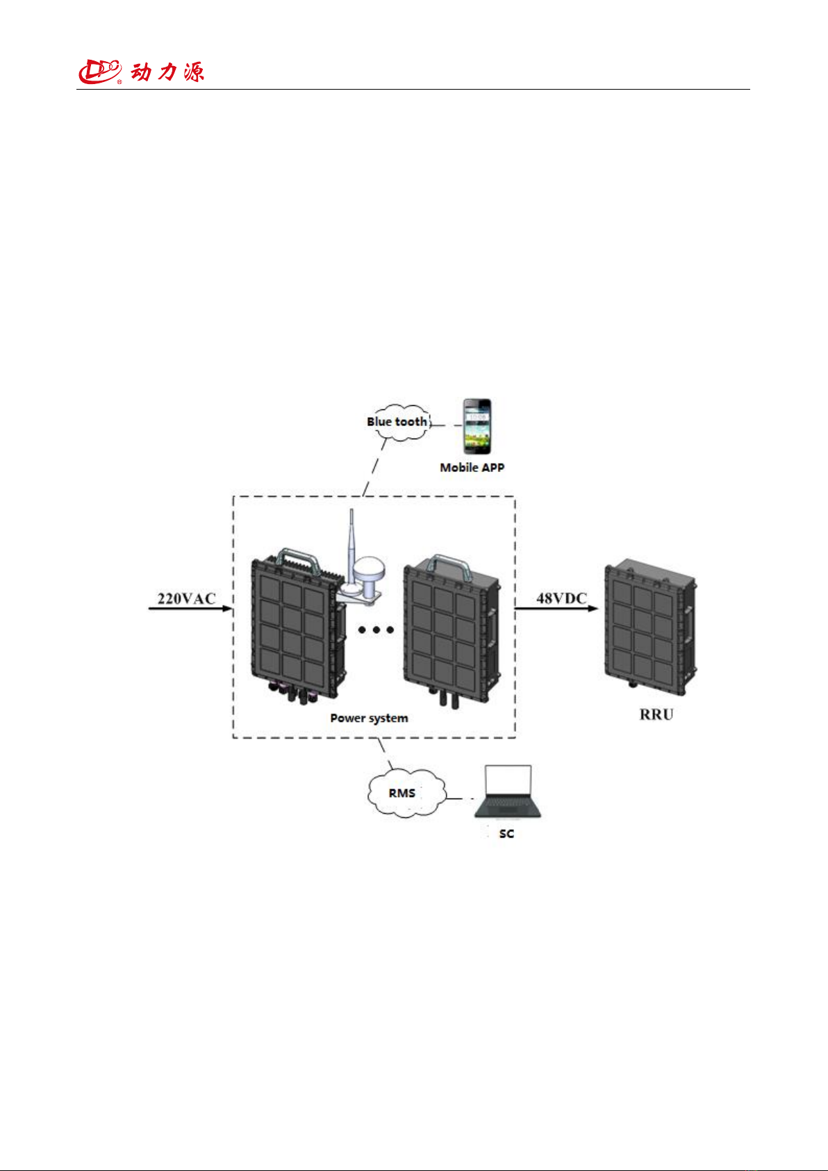
The small cell power system is applicable to the mobile tower, telecommunication, mobile, transmission,
access network, as well as the private network field such as hydraulic power, army, public security, railway,
bank, computer center and other dc power supply system. ............................................................................... 8
1.3 varieties and specifications;...................................................................................................................... 8
1.4 The composition of the model and its representative meanings.................................................................. 9
1.5 operation environment conditions ............................................................................................................... 9
1.6 Working conditions................................................................................................................................. 10
1.7 Impact on the environment and energy...................................................................................................... 10
1.8 Safety......................................................................................................................................................... 10
1.8.1 Insulation resistance.........................................................................................................................11
1.8.2 Electrical strength............................................................................................................................11
1.8.3 System contact earth current............................................................................................................11
1.9 Implementation standards...........................................................................................................................11
2 Structural characteristics and working principle....................................................................................................11
2.1 Overall structure .........................................................................................................................................11
2.2 Principle of work....................................................................................................................................... 12
2.3 2K power module configration............................................................................................................... 13
2.4 50AH Lithium module configuration........................................................................................................ 15
3 Technical feature................................................................................................................................................... 16
4 Installation............................................................................................................................................................ 17
4.1Mechanical installation............................................................................................................................... 17
4.1.1 Pole type......................................................................................................................................... 17
4.1.2 Parallel installation ......................................................................................................................... 19
2. 50AH Lithium battery Parallel installation.......................................................................................... 21
4.2 Electrical Installation................................................................................................................................. 22
4.2.1 Power cable installation.................................................................................................................. 22
4.2.2 Signal cable installation.................................................................................................................. 25
5 Use and operation................................................................................................................................................. 27
5.1 Use of Bluetooth APP::........................................................................................................................... 27
5.1.1 Installations ofAPP ........................................................................................................................ 27
5.1.2 Use of APP...................................................................................................................................... 27
5.2 SNMP Software User Manual ................................................................................................................... 33
5.2.1 WEB Service Explaination..................................................................................................................... 33
1)web Login.......................................................................................................................................... 33
2)Network Configuration...................................................................................................................... 34
3)SNMP Setting .................................................................................................................................. 35
4)Power real-time data view ................................................................................................................. 35
5)Historical alarm data query................................................................................................................ 36
5.2.2 CACertificate download and import...................................................................................................... 36
1)Certificate download.......................................................................................................................... 37