DPI KYNERGY 10-13B020T Series User manual

1
KYNERGY®AND INTELLIPHASE POWER® SERIES DC-DC CONVERTERS
GALVANICALLY ISOLATED & NON-ISOLATED –HI-EFFICIENCY
PRODUCT MODELS:
Non-Isolated Input To Output (Isolated From Chassis) KYNERGY®Series:
10-13B020Txx 24V Input, 13V 300W Dual Output, Switched + Continuous
11-13B020Txx 24V Input, 13V 300W Single Output, Switched
10-13D020Txx 36/48V Input, 13V 300W Dual Output, Switched + Continuous
11-13D020Txx 36/48V Input, 13V 300W Single Output, Switched
Isolated Input to Output And From Chassis INTELLIPHASE POWER®Series:
12-13D020Txx 36/48Vdc Input, 13Vdc 300W Single Output, Switched
12-13D030Txx 36/48Vdc Input to 13Vdc 400W Single Output, Switched
12-13F030Txx 72Vdc Input to 13Vdc 400W Single Output, Switched
Output Connector: xx = 08 Terminal Block Connector
xx = 50 Deutsch Style Connector.
xx = 55 Delphi Connector
xx = 95 Multi-Type I/O Connector
xx = 98 Flying Output Leads –no Connector supplied
xx = 99 Customer Specified Special-App Connector
IMPORTANT: READ AND SAVE THIS SAFETY
INSTRUCTION MANUAL.
Manual P/N: MNUL0023 Rev.6
Copyright © 2014 DPI
Diversified Power International
414 Century Court
Piney Flats, TN 37686
(423) 538-9002 (423) 538-9202 (fax)
www.DPIpower.com

2
Table of Contents
Part Description Pg Part Description Pg
1 Features 2 6 Operation 6
2 Introduction 2 7 Troubleshooting 7
3 User Safety 3 8 Wire Diagram Drawings 7
4 Personal Precautions 3 9 Mount Drill Templates 11
5 Installation And Mount 4 10 Warranty 12
Look for this symbol through out this manual. It means ‘BE
ALERT –YOUR SAFETY IS INVOLVED’. If you do not
follow these safety instructions, personal injury or property
damage may occur.
1. FEATURES
1.1. Fully Automatic –many faults such as Under Voltage conditions automatically
recover once condition returns to normal.
1.2. Environmentally sealed –fully encapsulated construction provides protection
from full water immersion.
1.3. Isolated models are Galvanically isolated from Input to Output from its Chassis
1.4. Non-Isolated models are Galvanically isolated from Leads to Chassis
1.5. Very high electrical energy conversion efficiency exceeding 91%, very low
radiated and conducted noise emissions.
2. INTRODUCTION
•The Diversified Power International (DPI) DC-DC Galvanic Isolated DC-DC
Converter series represents a design performance breakthrough allowing superior
regulation over a very large input range.
•It is designed to supply power to resistive and reactive loads such as motors and
Halogen Lamps (reference wiring diagrams for inductive motor load setup).
•A Keyed Switch Input allows operation setup from the primary battery side and
implements functions such as ‘Ignition Key’ or Winch Motor activation.
CAUTION: Incorrect or marginal wiring practices such as
loose wire to wire connections / crimps, omitted fusing at
battery terminals and poor connector crimp terminations may
result in equipment and/or property damage, or worse –
personal injury. Defer installation to qualified electricians.
Failure to follow mounting installations may void warranty –
Refer to ‘Installation and Mount’ Section.

3
3. USER SAFETY OPERATIONS GUIDE
WARNING: RISK OF EXPLOSIVE GASES.
WORKING WITH RECHARGEABLE BATTERIES IS
DANGEROUS. EXPLOSIVE GASES DEVELOP DURING
NORMAL BATTERY OPERATION. READ THIS MANUAL
EACH TIME AND MAKE CERTAIN YOU FULLY
UNDERSTAND IT AND FOLLOW THE SAFETY AND
OPERATING INSTRUCTIONS AT ALL TIMES.
3.1. To reduce risk of battery explosion, follow all safety instructions below and
those published by the battery manufacturer. Review cautionary markings on
vehicle or equipment containing the battery.
3.2. DC-DC Converter contains no serviceable parts. If it fails during its warranty
period, contact your dealer for a warranty replacement or refer to last page of
manual for replacement procedure.
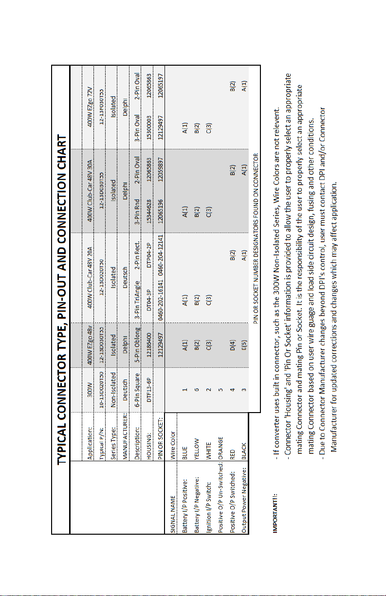
3.3. Construct cabling using DPI Approved and DPI supplied Connector Housing
and Connector pins and sockets.
3.4. The use of undersized conductors is STRICTLY prohibited. Ensure that any
wiring added to the input or output can safely carry the DC Current expected.
Plan to use wire gauges sufficient to carry input Currents of 15Amps typical
and output currents of 30amps typical. Wire and Cables must meet Automotive
and UL and/or CSA standards and routed to avoid being tripped over and not
subjected to damage or stress. Extension cables must be properly wired and in
good electrical condition, and large enough for the Ampere rating of the DC To
DC Converter Product as specified in the following TABLE:
RECOMMENDED MINIMUM AWG SIZE FOR WIRE AND CABLE
For 16A Input and for cable up to 25ft: Use 14Ga minimum
For 16A Output and for cable up to 25ft: Use 14Ga minimum
For 30A Output and for cable up to 25ft: Use 10Ga minimum
3.5. If Branch Circuit Wiring supplies multiple loads, such as that used from a Fuse
Block or Fuse Box, refer to the National Electrical Code (NEC) for wire gauges
appropriately sized to carry the load currents.
4. PERSONAL PRECAUTIONS While Working With Batteries
4.1. Have someone within range of your voice to come to your aid if needed.
4.2. Have plenty of fresh water and soap nearby in case battery acid contacts your
skin, clothing or eyes. Wear eye & clothing protection & avoid touching eyes.
4.3. If battery acid contacts skin or clothing, wash immediately with soap and water.
4.4. If acid enters eye, immediately flush eye with running cold water for at least 10
minutes. Get medical attention immediately.

4
4.5. NEVER smoke or allow a spark or flame in vicinity of battery.
4.6. Be extra cautious not to drop a metal tool onto battery. It might spark or short
circuit battery or other electrical part that may cause an explosion.
4.7. Remove personal metal items such as rings, necklaces, watches, etc. Batteries
can produce a short circuit current high enough to weld such items causing a
severe burn.
5. INSTALLATION
WARNING: NEVER connect loads to connection points in-
between battery interconnects such as those that connect one
battery to the next because it will cause the battery pack to
become unbalanced and dangerous to use. Always connect DC-
DC Converter across the entire Battery Pack –refer to
‘Correct / Incorrect Wiring Diagram Drawing’.
5.1. Installation should be performed by a Qualified Electrical Technician trained
and certified to work with Automotive and Mobile Equipment or vehicles.
5.2. Description of Wire Colors and Connection if supplied with Wire Leads
5.2.1. Input Wires:
Blue: Battery Positive
Yellow: Battery Negative
White: Ignition Key –if tied (shorted) to Battery Positive, Converter
output will energize (ON). If left floating, or shorted to
Battery Negative, Converter output will de-energize (OFF).
5.2.2. Output Wires:
Red: +13Vdc Output Load Positive
Black: - Negative Load Return
5.3. If supplied with Connector, refer to Wire Diagram Drawings.
5.4. Refer to the Mount Drill Templates Section for drill-hole diameters. Mount
surface MUST be clean of all grease, grime and all debris. Use of a thermal
transfer compound is recommended –apply a thin layer to the mounting area
prior to laying the Converter into place. Figure-A Mounting Voids Warranty.

5
5.5. Ensure Vehicle Ignition Key is off and turn Battery Disconnect off so that the
Battery Pack is completely disconnected from Vehicle and loads. If a disconnect
switch is not available, disconnect Positive and Negative Cables from Battery
Pack. Confirm disconnection by checking with a voltmeter from frame to
positive and negative battery terminals. If not familiar with the use of
voltmeters: STOP Installation, and refer service to a Qualified Electrical
Technician.
5.6. Using a Voltmeter and Ohm-meter, check and verify all wiring connections in
accordance with Wiring Diagram Drawing used.
WARNING:PROPER FUSING MUST BE INSTALLED BY USER.
On cables constructed to run from Battery Positive (+) Terminal to the
Converter Positive (+) input, a Waterproof Automotive Grade in-line Fuse
holder must be installed within 6inches (15cm) from Battery Positive (+)
Terminal. On the cable constructed to run from the Converters High
Output Positive (+) terminal to the electrical load(s), install a Waterproof
and Automotive Grade in-line Fuse holder and place this fuse holder within
6inches (15cm) of the Converter Terminals Positive (+) output. For every
output circuit originating from the output of the Converter, the installer
must ensure that EACH CIRCUIT is fitted with its own Fuse where the
fuse is properly rated to protect the load that it services.
WARNING: Wire connections to Connector Pins and Fuse
Holder Connect terminals must be BOTH crimped and
soldered to assure mechanical AND electrical bondage. 30 amp
currents are Welding Current Levels and improper
connections may result in heat points, fire and/or permanent
equipment / property damage and/or worse: personal injury.
CAUTION: Using Ohm Meter, check for wiring to chassis
shorts, and wiring to wiring shorts. Also check all nut and bolt
fasteners (if any used) for tightness of connections and ensure
that these connections have been properly protected from
environmental exposure with the use of grease or similar
materials. Check and Confirm polarity of output wiring prior
to making any connections to electrical loads.
5.7. Ensure all electrical loads are disconnected from Converter’s output. Enable
Battery Pack Disconnect Switch and/or reconnect Battery cables back to Battery
Pack Terminals to apply power to the converter.

6
5.8. Converter relies on conduction of heat to ambient air. An unpainted metal
surface of 36sq.in. and unobstructed air flow is required for maximum output.
5.9. Enable the converter by engaging the Ignition Key Switch. Using a voltmeter,
check and confirm output voltage from Converter High Power Output Channel
is 13.0Vdc +/-0.5V and that the polarity of the output is correct. Connect
electrical loads and verify operation of these loads.
5.10. If ‘UNSWITCHED’ operation is desired – meaning that the output of the
Converter is always energized (ON), permanently short the White Ignition
Wire to the Blue Input Battery Positive Connected Wire.
5.11.Some models supply a Dual Output Function where one output is continuous
enabled while a second output is switched. Load power is shared between both
outputs such that each output can produce up to the maximum rating of the
converter, as long as the TOTAL output power does not exceed the maximum
rating.
6. OPERATION
6.1. Input Ignition Key:
6.1.1. A SPST Switch serves as an ignition key. When the Key is in the ‘ON’ or
shorting position, the Converter output is energized (ON). When the Key
is in the ‘OFF’ or open position or left floating (un-terminated), the output
is de-energized (OFF).
6.1.2. The ignition key is a SPST type switch that connects the White Ignition
Key Input Wire to the Blue Input Battery Positive Wire. Alternately, if the
intent is to operate the Converter continuously without switching the
Converter Output, the White Ignition Key Input Wire should be shorted or
permanently connected to the Blue Input Battery Positive Wire.
6.2. When referring to Wiring Diagram Drawings:
6.2.1. ‘B+’ and ‘B-‘are Battery Positive and Negative inputs, respectively.
6.2.2. ‘Enable’ is also synonymous with ‘Input Ignition Key’. This input, when
pulled to ‘B+’, activates the ‘Switched Output’.
7. TROUBLESHOOTING GUIDE
7.1. Converter has no accessible user serviceable parts due to environmental sealing.
7.2. If electrical loads are not operating:
•Check that the load is functional and not defective
•Check all fusing, check for blown or open fuses
•Check wiring for breaks
•Check all Connectors, Wire Terminating Terminals, and/or Wire-Nuts for clean
connections, void of all corrosion
•Check all interconnect wiring points such as crimps

7
8. WIRING DIAGRAM DRAWINGS

8

9

10
IMPORTANT: CONVERTER IS NOT A BATTERY CHARGER
AND DOES NOT CONTAIN A BACKFEED DIODE PROTECTOR.
IF THE BATTERY CONNECTED TO THE CONVERTER INPUT FALLS
BELOW THE VOLTAGE OF THE BATTERY CONNECTED TO THE OUTPUT,
THE CONVERTER’S INPUT FUSING WILL OPEN CAUSING A PERMANENT
NON-WARRANTY CONDITION. INSTALLATION OF A BACKFEED DIODE
IN THE INPUT OR IN THE OUTPUT CIRCUIT IS MANDATORY SHOULD
THE INSTALLATION REQUIRE CHARGING A BATTERY. REFER TO A
QUALIFIED AND KNOWLEDGEABLE INSTALLER WHO IS FAMILIAR
WITH SIZING A BACKFEED PROTECTION DIODE OR CALL US TO
SUPPLY YOU WITH AN APPROPRIATE BACKFEED DIODE KIT. When using
a Solar Panel for Input, ensure the solar panel uses a Backfeed diode protector.

11
MOUNT DRILL TEMPLATES
ISOLATED CONVERTER DRILL TEMPLATE
Note: Base Plate Design is intentionally sized to allow for a Drop-In
Replacement mounting into Club Car 2-hole mount pattern.
NON-ISOLATED CONVERTER DRILL TEMPLATE
Note: DPI’s 2-Hole Base Plate Design intentionally sized to allow
Drop-In Replacement mounting into many competitors’two or
four or six-hole mounting patterns.

12
10 WARRANTY
Diversified Power International LLC (DPI) warrants exclusively to the original purchaser
that this product will be replaced or repaired, at DPI’s option, if it fails during the first 2
years after date of purchase due to a defect in material or workmanship or 3000 hours of
operation (internal time keeping mechanism employed). In order for a claim to be
processed the product must be returned to DPI (i) with all transportation charges prepaid,
(ii) accompanied by a acceptable proof of purchase, and with a Return Material
Authorization (RMA) number, previously obtained from DPI, printed and clearly visible
on the outside of the shipping container. This warranty does not apply if the product has
been modified, abused, mounted onto a curved surface causing physical product
damage or improperly or negligently used, connected, maintained, or operated in any
manner contrary to the instructions stated in this manual or in addition to instructions
which may be affixed to the product’s enclosure. Repair or replacement as provided
under this warranty is the exclusive remedy of the purchaser, and the purchaser shall have
no claim against DPI except for the breach of an express warranty stated herein. DPI shall
not be liable for any incidental, consequential, or special damages for breach of any
expressed or implied warranty. Except to the extent required by applicable law any
implied warranty of merchantability or fitness for a particular purpose is limited in
duration to the first two (3) years or 3000hrs of operation, after the date of purchase.
Some states do not allow the exclusion or limitation of incidental or consequential
damages or allow limitations on how long an implied warranty lasts, so the above
limitations or exclusion may not apply to you. This limited warranty gives you specific
legal rights, and you may also have other rights which vary from state to state. Apart
from the warranties set forth above, dpi makes no other warranty, express or implied,
with respect to the suitability or merchantability of this product, the fitness or this product
for any specific use or purpose, or any other matter pertaining to this product.
Return information:
DIVERSIFIED POWER INTERNATIONAL LLC
414 CENTURY COURT
PINEY FLATS, TN 37686, U.S.A.
423 538-9002
RMA # ________________
For further information, product updates, technical information, or general inquiries,
please visit our web site at:
www.DPIpower.com
This manual suits for next models
6
Table of contents
Popular Media Converter manuals by other brands

ADS Technologies
ADS Technologies HDUP-1500 operating instructions

Questtel
Questtel B-HDMI-ASI-IP-4CH user manual

MRC
MRC SOUNDER 0001866 quick start guide

D-Link
D-Link DMC-300SC - Media Converter - External user manual

MIDI hardware
MIDI hardware MIDECO user manual

StarTech.com
StarTech.com SAT32MSAT257 user guide

Asus
Asus Xonar Essence STU Quick start guides

ABB
ABB ACS150 series Quick installation and start-up guide

CAMBOARD
CAMBOARD Extron Electonics YCV 100 user manual

Pepperl+Fuchs
Pepperl+Fuchs KFD2-WAC2-Ex1.D instruction manual

Toshiba
Toshiba TOSVERT VF-AS3 instruction manual

LH Technologies
LH Technologies LH 500 Operator's manual