DPS Telecom NetGuardian LPG D-PK-NGLPG User manual

USER MANUAL
NetGuardian LPG Controller
February 15, 2019
Visit our website at www.dpstelecom.com for the latest PDFmanual and FAQs.
Firmware Version 1.0A
D-PK-NGLPG
D-UM-NGLPG

© 2015 DPS Telecom
This document contains proprietary information which is protected by copyright. All rights are reserved. No part of this
document may be photocopied without prior written consent of DPS Telecom.
All software and manuals are copyrighted by DPS Telecom. Said software and manuals may not be reproduced, copied,
transmitted or used to make a derivative work, by either mechanical, electronic or any other means in whole or in part, without
prior written consent fromDPS Telecom, except as required by United States copyright laws.
The materialin this manualis for information purposes and is subject to change without notice. DPS Telecomshallnot be
liable for errors contained herein or consequential damages in connection with the furnishing, performance, or use of this
manual.
Notice
Revision History
February 15, 2019
June 3, 2015
Minor updates
Initial Release

Contents
Visit our website at www.dpstelecom.com for the latest PDF manual and FAQs
NetGuardian LPG Controller Overview1 1
Specifications2 2
Shipping List3 4
Optional Shipping Items - Available by Request3.1 6
Installation4 7
Tools Needed4.1 7
Mounting4.2 7
NetGuardian LPG Controller Front Panel5 7
NetGuardian LPG Controller Back Panel6 9
Power Connection6.1 9
Valve Controls6.2 10
Tank Level Sensors6.3 10
Generator6.4 10
Quick Start: How to Connect to the NetGuardian LPG Controller7 11
...via Craft Port (using TTY Interface)7.1 11
...via LAN7.2 17
TTY Interface8 18
Configure Serial Port via TTY8.1 19
Quick Turn Up9 19
How to Send Email Notifications9.1 20
How to Send SNMP Traps9.2 22
Provisioning Menu Field Descriptions10 24
System10.1 25
User Profiles10.2 26
Ethernet10.3 27
RADIUS10.4 28
SNMP10.5 29
Notifications10.6 30
Notification Settings10.6.1 30
Schedule10.6.2 31
LPG Settings10.7 32
Alarms10.8 33
Controls10.9 35
User Analogs10.10 36
Sensors10.11 38
Ping Targets10.12 41

System Alarms10.13 42
Timers10.14 43
Date and Time10.15 44
Monitoring via the Web Browser11 45
LPG Automation11.1 45
Alarms11.2 45
Controls11.3 46
Sensors11.4 47
User Analogs11.5 48
Ping Targets11.6 49
System Alarms11.7 50
Graph11.8 51
Device Access Descriptions12 53
Backup Configuration13 54
Firmware Upgrade14 55
Reference Section15 56
Display Mapping15.1 56
System Alarms15.2 68
SNMP Manager Functions15.3 69
SNMP Granular Trap Packets15.4 71
Frequently Asked Questions16 72
General FAQs16.1 72
SNMP FAQs16.2 73
Technical Support17 74
End User License Agreement18 76

1
NetGuardian LPG Controller Overview
1
The NetGuardian LPG Controller
Meet the NetGuardian LPG Controller
The NetGuardian LPG Controller is ideal for remotely managing up to 4 liquid propane tanks. The LPG
Controller analyzes the propane flow from each tank to achieve a balanced consumption of propane
from all tanks assigned to the automation process. The unit also has an override feature, so that a tech
can manually turn on and off valves through the web browser interface. The NetGuardian LPG Controller
has an indicator LED for each tank showing valve status (open/close) and for trigger points for tank
level.
·1 Discrete Alarm Inputs
·1 D-Wire sensor input jacks, supporting up to 16 sensors (sold separately)
·1 Control Relay Output
·4 Valve Control Relays
·4 Analog Inputs
·Fast, integrated web browser
·32 ping targets to monitor other devices on the network
·24 VDC powered outputs that connect directly to LPGvalues.
·Monitors and powers LPG sensors.

2
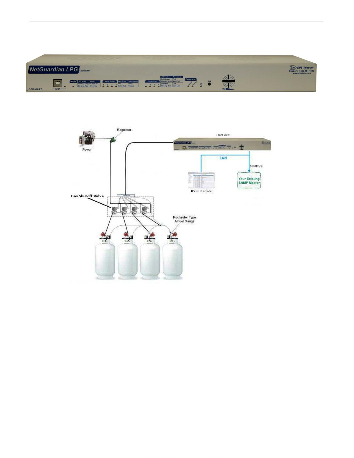
·Compatible with Rochester gauges.
·One discrete input for monitoring generator run.
·Supports HTTP and HTTPS, Email, SNMP v1, v2 and v3 notifications.
·Web configurable.
Specifications
2
Hardware
Dimensions:
1.720” H x 17.026” W x 7.336” D
Mounting:
19” or 23” Rack
Weight:
3lbs. 8oz. (1.59 kg)
Discrete Alarm Inputs:
1 (reversible)
2 Discrete Alarm Length:
2000Ft. per Alarm
Power Input:
–48 VDC (–36 to –72 VDC)
(Optional) –24 VDC
Analogs:
4
Input Range:
-92 to +92 VDC or 4 to 20mA
3 Current Draw:
100mA @ 48VDC
4 Analog Accuracy:
± 1% of Analog Range
200mA @ 24VDC
Fuse:
3/4 Amp GMT Fuse
Control Outputs:
1 Relay, 4 Valve control Relays
Max Voltage:
60 VDC/120 VAC
1 Power Outputs:
4 Sensor Power Outputs, 4 Valve Control
Outputs
Max Current:
1AAC/DC
Sensor Power Output:
+5VDC
Output Current:
100mA
Output Fuse:
None
Valve Control Voltage
Output:
+24 VDC
Output Current:
0.75A max per output / 3A total
Operating Temp:
32° to 140°F (0° to 60°C)
Output Fuse:
5 Amp GMT
1 Industrial Operating Temp:
-22° to 158°F (-30° to 70°C)
Storage Temp:
00° to 00°F (00° to 00°C)
Audible Interfaces:
Alarm Speaker
Operating Humidity:
95% non-condensing
Visual Interfaces:
13 Front Panel LEDs
4 Back LEDs
MTBF:
60 Years
RoHS:
RoHS 5 Approved
1 Hardware
Interfaces:
1 RJ45 10/100BaseT Ethernet port
1 USB front-panel craft port
Ordering Options:
1-4 RJ11 D-Wire sensor network
(Optional)
Software
Downloadable
Firmware:
Yes
D-Wire Sensor Support:
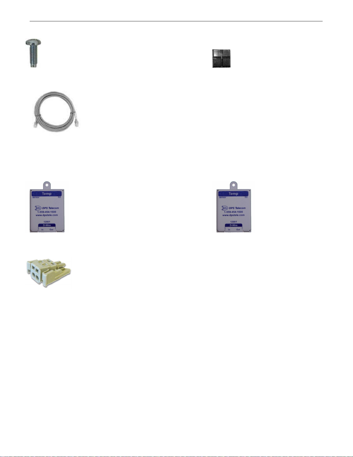
Temp, Temp/Humidity sensor
Built-in Web Interface:
Yes
1 built-in temp sensor (Optional)
Browser Support:
IE9, IE10, Firefox…..
Ping Alarms:
32
Protocols:
DCPx, TELNET, HTTP, Email….
SNMP Support:
V1, V2c, V3
OS Support:
XP, Vista, 7 (32 or 64 bit)
Note:
1Valid if hardware option is included.
2Minimum lengths determined with TTL voltage level alarms. Actual distance may vary.

3
3Current measured at rated voltage with all controls latched and all alarms triggered.
4See analog section in manual for detailed analog accuracy breakdown.
* This equipment has been tested and found to comply with the limits for a Class A digital device, pursuant to part 15 of the FCC Rules. These limits are designed to provide
reasonable protection against harmful interference when the equipment is operated in a commercial environment. This equipment generates, uses, and can radiate radio frequency
energy and, if not installed and used in accordance with the instruction manual, may cause harmful interference to radio communications. Operation of this equipment in a
residential area is likely to cause harmful interference in which case the user will be required to correct the interference at his own expense.

4
Shipping List
3
Please make sure all of the following items are included with your NetGuardian LPG Controller. If parts are missing,
or if you ever need to order new parts, please refer to the part numbers listed and call DPS Telecom at 1-800-622-
3314.
NetGuardian LPG Controller NetGuardian LPG Controller
D-PK-NGLPG Resource CD
NetGuardian LPG Controller User Manual 6 ft. USB Download Cable
D-UM-NGLPG D-PR-046-10A-06
x 3 x1
½-Amp GMT Fuses 5A GMT Fuse
2-741-00500-00 2-741-05000-00
x 2 x 2
19" Rack Ear 23" Rack Ear
D-CS-325-10A-00 D-CS-325-10A-01
x 8 x 4
Four 3/8" Ear Screws Two Metric Rack Screws
1-000-60375-05 2-000-80750-03

5
x4 x6
3 Point Locking Terminal 2 Point Locking Terminal
2-821-10335-00 2-821-10235-00
x 1
Lg. Power Connector (Main Pwr)
2-820-00862-02

6
x 4
Two Standard Rack Screws Pads
1-000-12500-06 2-015-00030-00
14ft. Ethernet Cable
D-PR-932-10B-14
Optional Shipping Items - Available by Request3.1
Temp Sensor Temp/HumiditySensor
D-PK-DSNSR-12001 D-PK-DSNSR-12002
Small WAGO connector
2-802-01020-00

7
Installation
4
Tools Needed4.1
To install the NetGuardian LPG Controller, you'll need the following tools:
Phillips No. 2 Screwdriver Small Standard No. 2 Screwdriver
PC with terminal emulator,
such as HyperTerminal
Mounting4.2
The NetGuardian LPG Controller can be flush or rear-mounted
The NetGuardian LPG Controller mounts in a 19" rack or a 23" rack using the provided rack ears for each size. Two
rack ear locations are provided. Attach the appropriate rack ears in the flush-mount or rear-mount locations shown in
Figure 6.2.1.
Note: Rack ears can be rotated 90° for wall mounting or 180º for other mounting options (not shown).
NetGuardian LPG Controller Front Panel
5
NetGuardian LPG Controller Front Panel
LED
Status
Description

8
FA
Solid Red
Blown Fuse
Off
Fuse OK
Demand
Red
Alarm
Off
Clear
Running
Green
Latched
Off
Released
Power
(Lamp)
Solid Green
Processor has power
Off
Processor does not have power
Craft
Blinking Green
Data Transmitted over USB
Blinking Red
Data Received over USB
Lnk
Solid Green
LAN Connected
Off
LAN Not Connected
LAN
Flashing Yellow
Activity over Ethernet Connection
Off
No Activity
100BT
Solid Green
LAN Connection Speed is 100BaseT
Off
LAN Connection Speed is 10BaseT
Tank Levels
Solid Green
Full
Blinking Green
Med-Full (Minor Over)
Solid Red
Low (Minor Under)
Blinking Red
Very Low (Major Under)
Valve Status
Off
Open
Solid Red
Closed
Front Panel LED Descriptions

9
NetGuardian LPG Controller Back Panel
6
The Back Panel of the NetGuardian LPG Controller
Power Connection6.1
The NetGuardian LPG Controller uses a single power input, powered through one barrier plug power connector.
NetGuardian LPG Controller Power Terminals and Fuses
To connect the NetGuardian LPG Controller to a power supply:
1. Locate the metal grounding lug next to the symbol . Use the grounding lug to connect the unit to earth ground.
2. Insert the eyelet of the earth ground cable between the two nuts on the grounding lug (Ground cable not included).
3. Choose a barrier plug power connector to attach your power cable to. One plug is used for main power and the
other is used for backup power. Both plugs are interchangeable so it does not matter which plug you select. Each
plug's right terminal is Ground and its left terminal is Battery Lead.
4. Insert a battery ground into the power connector plug's right terminal (GND) and tighten the screw.
5. Insert a battery lead to the plug's left terminal and tighten its screw.
6. Insert fuse into the fuse distribution panel.
7. Check the power status LED for polarity.
8. Measure voltage. Connect the black cable onto the ground connector of your Digital Voltage Meter (DVM) and red
cable onto the other connector of your DVM. The voltmeter should read between the values listed on the silk
screen next to the power connector.
9. Insert the local fuse into the power fuse slot. The power plug can be inserted into the power connector only one
way to ensure the correct polarity.
Note: The negative voltage terminal is on the left and the GND terminal is on the right.
10.Verify that the LED is lit. To confirm that power is correctly connected, the front panel status LED will flash
RED and GREEN, indicating that the firmware is booting up.

10
Valve Controls6.2
Valve Controls on the NetGuardian LPG Controller
The 5 AMP GMT fuse powers the controloutputs. These valve controls operate the valves on eachofthe 4
propane tanks.
Tank Level Sensors6.3
The Tank Level Sensor Inputs on the NetGuardian LPG Controller.
The Tank LevelSensor inputs monitor the fuellevels in the tanks. They supply 5V for the propane sensor.
Generator6.4
The Generator ports on the
NetGuardian LPG Controller
Demand is a user controloutput. Runningis a user discrete alarminput.

11
Quick Start: How to Connect to the NetGuardian LPG
Controller
7
Most NetGuardian LPG Controller users find it easiest to give the unit an IP address, subnet and gateway through
the front craft port (TTY interface) to start. Once these settings are saved and you reboot the unit, you can access it
over LAN to do the rest of your databasing via the Web Browser interface.
Alternative option: You can skip the TTY interface by using a LAN crossover cable directly from your PC to the
NetGuardian LPG Controller and access its Web Browser.
...via Craft Port (using TTY Interface)7.1
NetGuardian LPG Controller Craft Port
Use the front panel craft port to connect the NetGuardian LPG Controller ITto a PC for onsite unit configuration.
To
use the craft port, connect the included DB9 download cable from your PC's COM port to the craft port.
Note: The following images display the setup process done in Windows XP.
The following steps will occur the first time any DPS USB equipment is used on this PC. If you've used a
different DPS USB device before and have installed the DPS USB drivers, then skip to Step 9.
When you first connect the NetGuardian LPG Controller to your PC via USB, a "Found New Hardware" message
will appear:
1. Click the "Found New Hardware" message/icon to launch the "Found New Hardware Wizard".

12
2. Select "Install from a list or specific location (Advanced)"
3. Click "Next >"
4. Select "Search for the best driver in these locations."
5. Insert NetGuardian LPG Controller Resource Disc (CD) into your PC.
6. Click "Browse"

13
7. Select the "Driver" folder of your NetGuardian LPG Controller Resource Disc Disc (CD) and click "OK"
The following message will confirm installation of a new "USB Communications Port"
8. Click "Finish" to close the Wizard.
Now that the driver has been installed, a new COM port is being emulated on your PC. Before using
hyperterminal, you must confirm the identity of that new COM port (COM1, COM2, COM3...) in the Windows
Device Manager.

14
9. Right-click the "My Computer" icon on your desktop, then click "Manage"
10.Click "Device Manager" in the left pane.

15
11.Expand the "Ports (COM & LPT)" section in the right pane. Look for "USB Communications Port (COMx)".
Note the number of the COM port ("COM3" in the example above).
12.Click on the Start menu > select Programs > Accessories > Communications > HyperTerminal.
13. At the Connection Description screen, enter a name
for this connection. You may also select an icon. The
name and icon do not affect your ability to connect to
the unit.
14. At the Connect To screen, use the drop-down
menu to select the COM port you found earlier in the
Device Manager.

16
15. Select the following COM port options:
• Bits per second: 9600
• Data bits: 8
• Parity: None
• Stop bits: 1
• Flow control: None
Once connected, you will see a blank, white
HyperTerminal screen. Press Enter to activate the
configuration menu.
16. When prompted, enter the default user name
admin and password dpstelecom. NOTE: If you
don't receive a prompt for your user name and
password, check the Com port you are using on your
PC and make sure you are using the cable provided.
Additional cables can be ordered from DPS Telecom.
17. The NetGuardian LPG Controller's main menu will
appear. Type C for C)onfig, then E for E)thernet.
Configure the unit's IP address, subnet mask, and
default gateway.
18. ESC to the main menu. When asked if you'd like
to save your changes, type Y for Y)es. Reboot the
NetGuardian LPG Controller to save its new
configuration.
Now you're ready to do the rest of your configuration via LAN. Please refer to the next section "...via LAN" for
instructions on setting up your LAN connection.
Table of contents
Other DPS Telecom Controllers manuals
Popular Controllers manuals by other brands

Madas
Madas FRG-RG/2MCC manual

EP Solar
EP Solar Tracer-1206RN instruction manual

HYDRO-RAIN
HYDRO-RAIN HRC 390 SERIES Quick start instructions

Liebert
Liebert TELE2 user manual

Emerson
Emerson Fisher FIELDVUE DVC5000 Instruction manual supplement

ZIEHL-ABEGG
ZIEHL-ABEGG DControl PKDT Series operating instructions