Dr. A. Kuntze K 100 Cl2 User manual

Manual
K 100 Cl2, SCl2, ClO2, O2, O3, H2O2
K 100 W Cl2, SCl2, ClO2, O2, O3, H2O2
Measuringandcontrolinstrumentsforpotentiostatic
measurementsofChlorine,TotalChlorine,Chlorinedioxide,
Oxygen,Ozone,andHydrogenperoxide

Dr.A. Kuntze GmbH
Robert-Bosch-Str. 7a
D-40668 Meerbusch
Tel. +49-21 50-70 66-0
Fax +49-21 50-70 66-60
www.kuntze.com
Dr. A. Kuntze
Gutes Wasser mit System

3
K 100 (W) Cl2, SCl2, ClO2, O2, O3, H2O2
Contents
1. Your K 100 .....................................................................................................4
1.1General and Safetyinstructions ...............................................................5
1.2Application ...............................................................................................6
1.3Intendeduse ............................................................................................6
1.4Features...................................................................................................7
1.5Technicaldata ..........................................................................................8
2. Instructions for installation and connections .............................................9
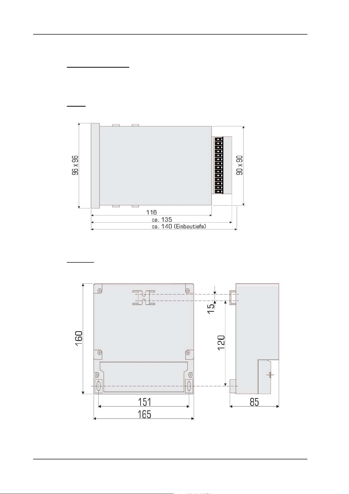
2.1Dimensions ............................................................................................ 10
2.2 Installation K 100 ................................................................................... 11
2.3 Installation K 100 W ............................................................................... 12
2.4Connection diagram K100 ..................................................................... 13
2.5 Connection diagram K 100 W................................................................. 14
3. Operation of the instrument....................................................................... 15
3.1How to adjustparameters....................................................................... 16
3.2Where to lookforinformation.................................................................. 17
3.3Menuoverview ........................................................................................ 18
4. Code and laguage...................................................................................... 19
5. Adjustment of the meter ............................................................................ 20
5.1 Calibration .............................................................................................. 21
5.2Temperaturecompensation .................................................................... 22
5.3Automatic sensorcleaningASR(option)................................................. 23
5.4Averaging ............................................................................................... 23
6. Adjustment of the controller ...................................................................... 24
6.1ON/OFFcontroller .................................................................................. 25
6.2P /PIcontroller asimpulse-frequencycontroller..................................... 26
6.3 P / PI controller as pulse-pause controller .............................................. 27
6.4Activation and deactivationofthecontroller............................................. 28
6.5Turn-ondelay ......................................................................................... 28
6.6External controllerstop(digital input) ..................................................... 28
6.7Manual operation oftherelays................................................................ 29
6.8 Dosage check ........................................................................................ 30
7. Data output.................................................................................................. 31
7.1Currentoutput ........................................................................................ 31
7.2Current output ascontrolleroutput ......................................................... 31
7.3Serialinterface RS485 (option) ............................................................... 31
8. Limit values and Alarm.............................................................................. 32
8.1Alarm ..................................................................................................... 33
8.2Configurationof the alarmrelay .............................................................. 34
8.3Error messages...................................................................................... 35
9. Operation and maintenace........................................................................ 36
10. Service ...................................................................................................... 38
Index ............................................................................................................... 39
Customer settings - for reference! ................................................................. 41

K 100 (W) Cl2, SCl2, ClO2, O2, O3, H2O2
4
1. Your K 100
Is an instrument by Dr. A. Kuntze GmbH which offers high quality and reliability for
years.
It is one of our economy series K 100 with which we are trying to meet the rising
demand for low cost / high end instrumentation.
The K 100 instruments are defined by an excellent value for money. They were
developped to maximize functionability on standard applications.
Operation requirements are reduced to an absolute minimum: The instrument is
delivered ready-to-use with a pre-adjusted working potential suitable for your
measurement. It is even pre-calibrated, so you will receive approximate measured
values immediately after installation. Single-point calibration is used to determine the
electrode´s response characteristic.
K 100 instruments are now optionally available with Automatic Cleaning function ASR.
The patent-pending electrochemical cleaning function prevents coatings of lime, rust,
or grease, and drastically reduces maintenance requirements.
All K 100 instruments have an integrated controller which provides bidirectional PI
control, via two relays or as a steady-state controller via the analog output. You can
define a turn-on delay to prevent incorrect dosage after power failure and operate the
controller by remote control. Connect a level sensor, and the fail-safe will shut down
the controller automatically in a low water situation. Activate the dosage check function
to get an alarm if dosage achieves no results, indicating damages in the feeding lines.
New: Now you can configure the alarm relay as NO or NC, so that power failure gives
an alarm, too, and as pulse contact instead of permanent contact, to fit all kinds of
subsequent security systems. Furthermroe, input errors and low water are now
indicated via anlog output in addition to the relay/display indication.
Let´s not forget the alarm function with minimum and maximum limit and turn-on
delay...
You have certainly made a good choice. On the following pages you learn more about
your K 100. If, however, you have further questions or are looking for information not
included in this manual or if you are interested in supplementing products like
sensors or flow cells or in our other instrument series, just give us a call - we will be
delighted to help you!

5
K 100 (W) Cl2, SCl2, ClO2, O2, O3, H2O2
1.1 General and Safety instructions
This manual applies to the following instruments:
Instrument and type Revision date
K 100 Cl2, K 100 W Cl204/09
K 100 SCl2, K 100 W SCl204/09
K 100 ClO2, K 100 W ClO204/09
K 100 O2, K 100 W O204/09
K 100 O3, K 100 W O304/09
K 100 H2O2, K 100 W H2O204/09
It contains technical information for the installation, start-up and maintenance. If you
have any questions not included in this manual please contact your supplier or the
official representative of Dr. A. Kuntze GmbH in your country.
We would like to point out that the warranties specified in our general trading
conditions are valid only if
- installation, connections, adjustments, start-up, and maintenance of the
instrument are carried out by authorized personnel with adequate qualification.
- the instrument is used according to the description in this manual.
Please check for damages immediately after receiving the instruments and report any
damages within 24 hours to the delivering company. Never work with a damaged
instrument.
Keep this manual at a safe place where you can always look up the safety instructions
and the informations on handling and usage. According to DIN 61010 the manual is
part of the product and must be maintained as long as the instrument is used, and
given to the next owner if the instrument is sold.
This instrument was designed and built according to the safety measurements for
electronic devices and has left our company in perfect working condition. To preserve
this condition and to ensure safe usage follow all instructions carefully and pay special
attention to all warnings issued in this manual. If the instrument is visibly damaged or
has been stored inappropriately or if there are any doubts concerning safe usage, shut
it down and make sure it cannot be restarted by accident.
You will notice that important safety instructions are highlighted:
WARNING highlights instructions for the protection of people. Disregarding these
instructions may cause accidents and injuries!
ATTENTION higlights instructions for the protection of the instrument and the
equipment. Disregarding these instructions may lead to damage or
destruction of the instrument or equipment!
NOTE is used to highlight interesting details.
1.1 General and safety instructions

K 100 (W) Cl2, SCl2, ClO2, O2, O3, H2O2
6
1.2 Application
The instruments K 100 Cl2 and K 100 W Cl2 can be used to measure the
concentration of free Chlorine in water. The other instruments measure the
concentrations of their specific parameters. Alle have an integrated controller with two
set points. With this you can control actuators such as dosing pumps or valves to add
chemicals until the desired concentration is reached and maintained.
Applications are detoxication of industrial waste water, water treatment, and
desinfection.
While the controller is set to Automatic, it controls independently the dosing of possibly
hazardous chemicals, according to the measured values.
For safety measures, both the measurement and the calibration are checked for
failure. Failures are indicated in the display and via the alarm relay, which can set off a
horn or lamp or relate to a central control. If that failure makes control unreliable, the
controller is automatically switched off until the failure has been taken care off.
CAUTION The instrument checks the input signals, the calibration results, and
the water flow, if a flow sensor is connected. It cannot detect
erroneous settings or failures in the treatment system, nor can it
check for plausibility! The safety of the system of which the
instrument is part of, lies within the reach of responsibility of whoever
built the system.
1.3 Intended use
Use these instruments only for the monitoring and control of water.
Use only sensors, fittings, and accessories of Dr. A. Kuntze, since instruments and
sensors are attuned.
Ensure that the required measuring conditions are constantly maintained, such as
flow, pressure, temperature, etc.
Set-up the instrument according to this manual. Carry out all the steps described, and
check all measurements and settings before you activate the controller.
Use all available safety measures such as the alarm relay, the dosage check, and the
lack-of-water indication.
Regularly check that all safety measures are in good working order.
CAUTION The protection built into the instrument is impaired if they are not used
as intended!
1.2Application and intendeduse

7
K 100 (W) Cl2, SCl2, ClO2, O2, O3, H2O2
1.4 Features
Meter
Measuring ranges 0.00 - 4.00 mg/l Cl2free Chlorine (K 100 (W) Cl2)
0.00 -10.00 mg/l TCl2total chlorine (K 100 (W) SCl2)
0.00 - 4.00 mg/l ClO2Chlorine dioxide (K 100 (W) ClO2)
0.0 - 20.0 mg/l O2Oxygen (K 100 (W) O2)
0.00 - 4.00 mg/l O3Ozone (K 100 (W) O3)
0.00 -30.00 mg/l H2O2Hydrogen peroxide (K 100 (W) H2O2)
-30.0 - 140.0 °C
Display Measured value and temperature with dimension
Status display sensor, calibration, controller & alarm
Temperature compensation manual or automatic with Pt100 (NTC for O2)
Calibration 1-point calibration; for Oxygen measurements in air
Averaging can be activated and deactivated via menu
Automatic Sensor cleaning (option) automatically recognised when connected
Controller
Set points 2 set points with adjustable direction
Controller types ON/OFF controller with hysteresis
P controller as Pulse-Pause-, Impulse-Frequency- or steady controller
PI controller as Pulse-Pause-, Impulse-Frequency- or steady controller
Hysteresis ajustable within the measuring range
P range XPadjustable within the measuring range
Integral time TN0 - 2000 sec.
Least pulse 0.1 - 9.9 sec.
Pulse+Pause time 02 - 99 sec.
Impulse frequency 100 - 7200 pulses/h
Turn-on delay 0 - 200 sec.
Dosage check 0 - 90 min
Alarm function min. and max. limit and onset delay
Connections
Relays 3 potential-free contacts (2x controller, 1x alarm)
6A, 250 V, max. 550 VA
Analog output 0/4-20 mA galvanically isolated, max. loading 500 Ohm
Analog inputs 1 measuring input for Cl2, TCl2, ClO2, O2, O3, or H2O2
1 measuring input for temperature sensor
Digital input external controller stop or low water indication
NC or NO selectable via menu
Serial interface RS485, Baud rate 9600, data formate 8Bit,
(Option) 1start and 1stop bit, no parity
1.4Features

K 100 (W) Cl2, SCl2, ClO2, O2, O3, H2O2
8
1.5Technicaldata
Installation panel-type housing wall-mounting housing
Dimensions 96 x 96 x 135 mm (WxHxD) 165 x 160 x 85 mm
Weight 0.8 kg 1.0 kg
Terminals screw terminals spring-loaded terminals
for cables up to 1.5mm2for cables up to 1.5mm2
Protection class Front IP54 IP65
Power supply 230 V +6/-10%, 40..60 Hz, optionally 117 V or 24 V
internal fuse none 230V: 63mA HRC
117V: 125mV HRC
24V: 800mA NRC
Power consumption 10VA
Contact rating 6A/ 250 V, max. 550 VAresistive load
(with RC protective circuit)
Operation temperature 0 - 50°C
Storage temperature -20 - +65°C
Humidity max. 90% at 40°C non condensing
view
Feature K 100 K 100 W
1.5 Technical data

9
K 100 (W) Cl2, SCl2, ClO2, O2, O3, H2O2
Current up to Capacitor C Resistance R
60 mA 10 nF 260 V 390 Ohm 2 Watt
70 mA 47 nF 260 V 22 Ohm 2 Watt
150 mA 100 nF 260 V 47 Ohm 2 Watt
1,0A 220 nF 260 V 47 Ohm 2 Watt
R
C
2.Instructions forinstallationand connections
2. Instructions for installation and
connections
Installation:
On the next pages you will find detailed instructions for the installation.
For panel-type meters you have to prepare an opening of 92x92mm. Install the
instrument and fix it with the two mounting clips which were part of the delivery.
You can install instruments in wall-mounting housings either by hanging them upon
the center slot or by sliding the slot under a screw, which is an alternative for limited
space. Either way you have to fix it additionally with two screws.
ATTENTION Install the instrument in a place where it is not put under mechanical
or chemical strain!
Mind the protection class:
K 100: Front IP54
K 100 W: IP65 (closed terminal cover)
Connections:
You will find detailed connection diagrams on the following pages.
Before connecting the power supply check the information on the instrument label!
ATTENTION Input, output and control lines must be installed separate from each
other and separate from power lines!
For inputs and outputs use screened lines and connect the screen on one side only.
The potentiostatic measurement is interference-sensitive, especially when using
membrane sensors. Use a special screened cable. Membran sensors are delivered
complete with cable.
For the connection of temperature sensors use a low-resistance cable with a large
diameter.
When using the relays, mind that with inductive loads, interference must be
suppressed. If that is not possible, the relay must be protected at the terminal block in
the K 100 by a resistance-capacitance filter or, in case of direct current, by a free-
wheeling diode.

K 100 (W) Cl2, SCl2, ClO2, O2, O3, H2O2
10
2.1 Dimensions
K 100 W
K 100
2.1 Dimensions

11
K 100 (W) Cl2, SCl2, ClO2, O2, O3, H2O2
2.2 Installation K 100
Prepare an
opening of 92 x
92 mm.
Screw tight until
the instrument is
fixedperfectly.
Install the
instrument from
the front side
and fix it with the
two mounting
clips which were
part of the
delivery.
2.2 Installation K 100

K 100 (W) Cl2, SCl2, ClO2, O2, O3, H2O2
12
2.3 Installation K 100 W
Remove the terminal
cover.
Drill three holes (max.
M5) according to the
drawing. Mind that there
are two ways for
installation: (1) You can
hang the instrument upon
the upper screw. In that
case drill the upper hole
120mm above the lower
two. (2) Or you can slip
the fixture on the back of
the isntrument under the
upper screw. In that case
the upper hole has to be
another 15mm higher.
Mount the instrument and
fix it with the two lower
screws. Close the
terminal cover or start
with the connections.

13
K 100 (W) Cl2, SCl2, ClO2, O2, O3, H2O2
PE
Sensor
Pt100/
NTC
0/4-20 mA
Dig. IN
Rel 1
Rel 2
Rel 3
L
N
1
2
3
4
5
6
7
8
9 +
10 -
11 +
12 -
13
14
5
4
3
2
1
9
8
7
6
RS 485
-+
15
16
17
18
19
20
21
22
23
24
25
26
K 100
M
K 100K 100
M
2.4Connection diagram K100
2.4 Connection diagram K 100
Connection Terminals Note
Sensors without 1 - 4 1 = Screen
electronics 2 = Measuring electrode
3 = reference electrode
4 = counter electrode
With 2-electrode sensors
short-circuit terminals 3 + 4
Membrane sensor 1 - 4 1 + 2 measurement
with electronics 3 = - 6 V
4 = + 6 V
Pt100 / NTC 5 + 6
Analog output 9 + 10 9 = +, 10 = -, max. load 500 Ohm
Digital input 11 + 12 11 = +, 12 = -, external controller stop
and / or low water indication
Relay 1 18 + 19
Relay 2 20 + 21
Relay 3 22 + 23 Alarm relay
Power supply 24 - 26 Check information on instrument label!
RS485 (Option) Sub-D 3 = +, 8 = -
4/7 bridged activates terminating resistance

K 100 (W) Cl2, SCl2, ClO2, O2, O3, H2O2
14
- + +
1 2 3 4 5 6 7 10 11 12 13 14 15 16 17 18 19 20 21 22
23 24 25 26 27 28
Sensor Pt100/NTC 0/4-20 mA Rel. 1 Rel. 2 Rel. 3 L N PE
RS 485 Dig. IN
A
Display
+ -
M
K 100
M
K 100
2.5 Connection diagram K 100 W
Connection terminals Note
Sensors without 1 - 4 1 = Screen
electronics 2 = Measuring electrode
3 = Reference electrode
4 = Counter electrode
Membrane sensors 1 - 4 1 = reference/GND
with electronics 2 = Measuring signal
3 = - 6 V
4 = + 6 V
Pt100 / NTC 6 + 7
Display-Kontrast Display Potentiometer to adjust brightness
Analog output 11 + 12 11 = +, 12 = -, max. load 500 Ohm
Relay 1 14 + 15
Relay 2 16 + 17
Relay 3 18 + 19 Alarm-Relais
Power supply 20 - 22 Check information on instrument label!
RS485 (Option) 23 + 24 23 = -, 24 = +
Jumper A activates terminating resistance
Digital input 26 - 28 26 = +, 27 = -, external controller stop
and / or low water indication
28 = +24 V DC for inductive flow sensors

15
K 100 (W) Cl2, SCl2, ClO2, O2, O3, H2O2
1 2 3 4 5 6
0.49 mg/l 25.0°C
S1
S2 Man
7 8 9 10 11
1 Measured value
2 Status relay 1
3 Status relay 2
relay OFF
relay ON
4 Temperature
5 Controller
AUTO: controller ON
MAN : controller OFF
(manual operation
of the relays)
HOLD: freezes analog
output and limit function
6 Orientation aids
7 Key left ()
8 Key up ()
9 Key down ()
10 Key right ()
3.Operation of theinstrument
3. Operation of the instrument
When turned on the instrument shows the measured value and temperature together
with the controller mode (Man) and the status of the relays S1 and S2 (both OFF).
With five membrane keys you can move within the menu:
With key you enter the main menu.
With keys and you move up and down in the menu.
With key you adress a menu or parameter.
With key you leave a menu or store a change.
For your convenience triangles in the display indicate the directions you can take from
your position in the menu.
From the display of the measured values you can switch the controller ON and OFF
with key in the order:AUTOHOLDMANAUTO.
With key „M“ you get back to the display of the measured values from any point in the
menu. Changes that have not been stored will be lost.
NOTE The instruments K 100 and K 100 W differ only in housing. Operation
and menus are the same.

K 100 (W) Cl2, SCl2, ClO2, O2, O3, H2O2
16
Temp. Comp.
Manual Comp.
Temp. Comp.
Automat. Comp.
Temp. Comp.
Manual Comp.
Enter code
058 Code
Enter code
058 Code
Enter code
062 Code
3.1How to adjustparameters
3.1 How to adjust parameters
1) When you adress a parameter the actual setting is
displayed.
2) Switch to the next alternative setting with key.
3) When you have come to the last alternative, pressing the
key once more will bring you back to the start.
Selection between alternatives
For many parameters you have the choice between two or more alternatives, e. g.
between manual and automatic temperature compensation. For these parameters you
need only key. Switch from one alternative to the next until you either come back to
where you started or until you reach the alternative you were looking for.
With these parameters any changes are immediately valid - there is no need to store
the change.
1) Adress the parameter with key.
2) A double triangle appears behind the number indicating
that the number can be changed now with keysand .
3) Store the new value with key. The double triangle
disappears - the new value is stored.
Adjustment of numerical parameters
Numerical parameters can only be altered when a double triangle is visible behind the
number. This double triangle appears when you adress the parameter with key.
Adjust the parameter with keys and . A short pressure on the key changes the last
decimal by 1. If you keep the key pressed, the value will continue changing until the
pressure is released.
Store the changes with key. The double triangle disappears.
NOTE If you do not want to store the change, press key „M“ instead of
key
.

17
K 100 (W) Cl2, SCl2, ClO2, O2, O3, H2O2
Calibrate
Temp. Comp.
Enter password
Set points
Limit values
Basic settings
Service
0.48 mg/l 25.0°C
S1S2 Auto
Main menu
Cal. Pt/NTC
Contr. settings
Start delay
Analog output
Language
Bus adress
Averaging
Temp. coeff.
Cleaning
Dig. input
Alarm relay
Basic settings
3.2 Where to look
3.2 Where to look for information
Main display
Enter the menu with key .
Information is in chapter:
Adjustment of the meter - calibration
Adjustment of the meter - temperature compensation
Code and language
Adjustment of the controller - ON/OFF, P/ PI controller
Limit values and alarm
Information is in chapter:
Adjustment of the meter - temperature compensation
Adjustment of the controller - ON/OFF, P/PI controller
Adjustment of the controller - activation and deactivation
Data output
Code and language
Data output
Adjustment of the meter - averaging
Adjustment of the meter - temperature compensation
Adjustment of the meter - automatic Sensor cleaning
Adjustment of the controller - activation and deactivation
Limit values and alarm
Main menu and basic settings
The parameters are sorted into two menus: In the main menu you will find all functions
which are used regularly, such as calibration. The menu basic settings contains all
parameters which are set just once during start-up.
On the following pages you will find information on how to adjust parameters and
which parameters you need for which application, in the following order:
1) General adjustments: password and language
2) Adjustments for measurement: calibration, temperature compensation,
averaging, flow, and cleaning (option)
3) Adjustments of the controller: selection of the controller version and
corresponding parameters
4) Adjustments to read out data: analog, digitally and/or as alarm

K 100 (W) Cl2, SCl2, ClO2, O2, O3, H2O2
18
Alarm relay
0.48 mg/l 25.0°C
S1S2 Auto
Main menu
3.3Menuoverview
3.3 Menu overview
Press key to enter the menu.
DPDcalibration
0.48 mg/l
Slope
025 mV
Temp. comp.
Manualcomp.
Temperature
25.0 °C
Enter password
056 Code
Set point S1
1.50 mg/l
P range S1
0.20 mg/l
Integraltime S1
000 sec.
Set point S2
0.50 mg/l
P range S2
0.20 mg/l
Integraltime S2
000 sec.
Calibrate
Temp.comp.
Enter password
Set points
Limit values
Basic settings
Basic settings
Cal.Pt/NTC
Contr. settings
Start delay
Analog output
CalPt/NTC
0.0 °C
Pulse-freq. S1
00*100/h
Pulse-freq. S2
00*100/h
Direction S1
raise
Direction S2
lower
Hysteresis
0.01 mg/l
Pulse+Pause
10 sek.
Min. pulse
0.1 sec.
Dosage check
S1 060min
Dosage check
S2 060min
Start delay
ON
Start delay
180 sec.
Select output
0 - 20 mA
Begin 0/4mA
0.00 mg/l
End 20 mA
4.00 mg/l
Analog output
Measuring value
Language
Bus adress
Averaging
We speak
English
Bus adress
Nr. 00
Averaging
ON
Temp. coeff.
Product info
Temp. coeff.
0.0%/K
Cleaning/day
1
Start delay
6.0 h
Analog inputs
Clearmemory
Service
Unit no.
Nr. 041
Software date
M/Y 1.00
Product. date
M/Y 1.00
Clearmemory
Press&
Service
Analog inputs
input 1 003 mV
Analog inputs
input 2 25.0°C
Dig.input
NO
Cleaning
Dig.input
Alarm relay
Normallyopen
Pulse contact
LimitS1
1.00 mg/l
LimitS2
0.30 mg/l
start delay
005 sec.
control. mode
Auto+Man

19
K 100 (W) Cl2, SCl2, ClO2, O2, O3, H2O2
.
Basic settings .
.
Language
Enter Password
056 Code
Main menu
Basic settings
We speak
english
Language
.
.
Enter password
4.Codeandlaguage
4. Code and laguage
Enter password
To get access to the various parameters you have to enter the correct password:
Code 11 gives access to the parameters „calibration“, „temperature
compensation“, and „set points“.
Code 86 gives access to all parameters and functions.
With any other number it is impossible to select, view or change any parameter.
.
Main menu
Enter password
Language
For the communication with the instrument you can choose from a variety of
languages.
Since choosing a language is part of the basic settings, it requires code 86. If a
different code is set, you will be asked to enter the correct password.

K 100 (W) Cl2, SCl2, ClO2, O2, O3, H2O2
20
Calibrate
Temp. comp.
.
.
.
.
Basic settings Cal. Pt/NTC
.
Averaging
Temp. coeff.
Cleaning
Hauptmenü
Basic settings
5. Einstellen des Messgerätes
5. Adjustment of the meter
Calibration of the measurement and display of slope.
Selection between automatic and manual temperature
compensation, adjustment of temperature for manual
compensation.
Calibration of the temperature measurement
Activattion of averaging function
Coefficient for linear temperature compensation
Cleaning interval and delay time (option)
Potentiostatic measurements require a 1-point calibration:
Since the measurement depends upon the flow-rate and calibration solutions would
not be stable anyway, the sensor cannot be taken out of the armature for calibration, as
is done with pH sensors. Instead the actual concentration of the test water is
determined by an alternative method, for example photometrically with DPD, and this
value is entered as calibration value. Calibration of the Oxygen measurement is
simpler, using the Oxygen concentration of the ambient air.
The measurement is influenced by temperature. This influence can be compensated
manually or automatically. For manual compensation the temperature is entered
manually, for automatic compensation temperature has to be measured with a
temperature sensor. For the temperature compensation a linear coefficient can be
adjusted as %/K.
For smoother measured values activate the averaging function.
If you have purchased an instrument with Automatic Sensor Cleaning ASR, the basic
settings will include „cleaning“ where you can activate the automatic cleaning, define
the interval between subsequent cleaning cycles and the time for the first cleaning
cycle.
NOTE The menu „cleaning“ appears automatically when a sensor with ASR
is connected.
This manual suits for next models
11
Table of contents
Other Dr. A. Kuntze Measuring Instrument manuals
Popular Measuring Instrument manuals by other brands

Kobold
Kobold TIN-SH operating instructions

Simex
Simex SRP-147-XC user manual

Hanna Instruments
Hanna Instruments HI 4110 instruction manual

Katronic
Katronic KATflow 170 Operating and safety instructions

Samson
Samson 411 110 Parts and technical service guide

Micromeritics
Micromeritics SediGraph III 5120 Service manual

DeWalt
DeWalt DCLE34021 instruction manual

Electro-Tech systems
Electro-Tech systems 863 Basic operating instructions

WPA
WPA LIGHTWAVE II user manual

Mobeye
Mobeye WaterGuard-FS CM2300FS user manual

Steinberg Systems
Steinberg Systems SBS-MM-100 user manual

Sartorius
Sartorius BioPAT Xgas Vis operating manual