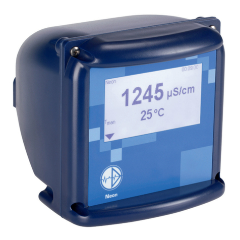
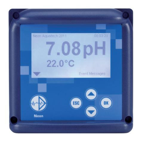
Dr. A. Kuntze Neon GAS User manual

Dr. A. Kuntze
Manual
Neon®Gas


Content
Dr. A. Kuntze IGutes Wasser mit System
Robert-Bosch-Str. 7a
40668 Meerbusch
+49 (0) 2150-7066-0 / Fax -60
www.kuntze.com
Content
1. Neon®Gas ............................................................................ 6
1.1. General and safety instructions......................................................... 7
1.2. Warranty conditions .................................................................... 7
1.2.1. Transport damages .................................................................... 7
1.2.2. Application ............................................................................. 8
1.2.3. Intended use ........................................................................... 8
1.3. Übersicht über die Funktionen.......................................................... 9
1.4. Technical Data Neon®.................................................................. 11
2. Instructions for installation and connections........................................ 12
2.1. Dimensions ............................................................................ 12
2.2. Installation panel-mounted housing ..................................................... 13
2.3. Installation wall-mounted housing. . . . . . . . . . . . . . . . . . . . . . . . . . . . . . . . . . . . . . . . . . . . . . . . . . . . . . . 14
2.4. Installation of sensor ................................................................... 15
2.5. Connections ........................................................................... 16
2.5.1. Connection diagram.................................................................... 17
2.5.2. SD card................................................................................ 19
3. Operation ............................................................................. 20
3.1. Desk to p ................................................................................ 20
3.2. Key pad operation...................................................................... 20
3.2.1. Main menu ............................................................................. 21
3.2.2. Submenus ............................................................................. 21
3.3. Touch screen operation ................................................................ 22
3.3.1. General ................................................................................ 22
3.3.2. Main menu............................................................................. 23
3.3.3. Submenus ............................................................................. 23
3.4. Settings................................................................................ 23
3.5. Menu overview – where to look?. . . . . . . . . . . . . . . . . . . . . . . . . . . . . . . . . . . . . . . . . . . . . . . . . . . . . . . . 26
3.6. Menu appearance depending on code and options...................................... 29
4. Code .................................................................................. 30
5. Analog input – gas measurement .................................................... 31

Content
Dr. A. Kuntze IGutes Wasser mit System Robert-Bosch-Str. 7a
40668 Meerbusch
+49 (0) 2150-7066-0 / Fax -60
www.kuntze.com
6. Menu Cal – Zeropoint calibration..................................................... 32
6.1. Calibration – zeropoint ................................................................. 32
6.2. Calibration – info ....................................................................... 33
7. Digital inputs ......................................................................... 34
8. Test menu............................................................................. 35
9. Memory ............................................................................... 36
9.1. Store and upload settings .............................................................. 36
9.1.1. How to save settings ................................................................... 37
9.1.2. How to load settings.................................................................... 38
9.2. Software update ....................................................................... 39
9.3. How to save the diagnosis file .......................................................... 40
10. System functions ..................................................................... 41
10.1. Language .............................................................................. 41
10.2. Time ................................................................................... 42
10.3. Display................................................................................. 43
10.3.1. Settings................................................................................ 43
10.3.2. Touch Cal – for instruments with touch screen . . . . . . . . . . . . . . . . . . . . . . . . . . . . . . . . . . . . . . . . . . 44
10.4. Contact ................................................................................ 45
10.5. Event-related support .................................................................. 46
10.6. Info .................................................................................... 47
10.7. Reset to factory settings................................................................ 48
10.8. Add-on activation ...................................................................... 49
11. Alarm relay............................................................................ 50
11.1. Settings ................................................................................ 50
11.2. Alarm action ........................................................................... 51
12. Add-on Datalog ....................................................................... 52
12.1. View logged data....................................................................... 54
13. Add-ons mA output................................................................... 55

Content
Dr. A. Kuntze IGutes Wasser mit System
Robert-Bosch-Str. 7a
40668 Meerbusch
+49 (0) 2150-7066-0 / Fax -60
www.kuntze.com
14. Add-on Modbus RTU ................................................................. 56
14.1. How to read out data ................................................................... 56
14.2. Communication parameters ............................................................ 57
14.3. Registers .............................................................................. 57
14.3.1. How to read variables .................................................................. 58
14.3.2. Measured values, controller outputs and status of digital inputs and outputs ............. 59
14.3.3. Event messages and calibration results................................................. 60
14.3.4. Instrument data ........................................................................ 64
14.3.5. How to read and write parameter settings............................................... 65
14.3.6. Units and texts ......................................................................... 72
14.3.7. Test functions .......................................................................... 74
15. Operation and Maintenance of Neon®Gas ........................................... 75
15.1. Start-up................................................................................ 75
15.2. Maintenance of the measurement ...................................................... 77
15.2.1. Calibration of the measurement ........................................................ 77
15.2.2. Zeropoint calibration................................................................... 77
15.2.3. Testing the safety features.............................................................. 78
15.3. Decommissioning and disposal......................................................... 78
15.4. Facilitating functions ................................................................... 78
15.4.1. Store and load settings via SD card .................................................... 78
15.4.2. Software update via SD card ........................................................... 78
15.4.3. Test menu ............................................................................. 78
16. Trouble-Shooting ..................................................................... 79
16.1. Useful accessories for trouble-shooting................................................. 79
16.2. Contact
. . . . . . . . . . . . . . . . . . . . . . . . . . . . . . . . . . . . . . . . . . . . . . . . . . . . . . . . . . . . . . . . . . . . . . . . . . . . . . . . 79
16.3. Diagnosis file .......................................................................... 79
16.4. Info .................................................................................... 80
16.5. Event messages ....................................................................... 80
16.6. Eventlog ............................................................................... 81
16.7. Event help ............................................................................. 81
16.8. Events with Popup messages .......................................................... 84
16.9. Reset .................................................................................. 85
Index ................................................................................ 86

1. Neon®Gas
6
Dr. A. Kuntze IGutes Wasser mit System Robert-Bosch-Str. 7a
40668 Meerbusch
+49 (0) 2150-7066-0 / Fax -60
www.kuntze.com
1. Neon®Gas
is a product by Dr. A. Kuntze GmbH which offer high quality and long-term reliability, made in Germany.
With its modular design, the Neon®Gas warning instrument can be tailored to your application.
The entry-level version contains two inputs for measurement, two digital inputs, and an alarm relay.
You can choose between key pad or touch screen operation.
A set of codes allows access to different operation levels. If you want to ensure that only authorized
personnel can operate the instrument, define an auto-lock time after which the code is reset to default
setting.
Save energy with the Eco mode, in which the display illumination is deactivated after an adjustable
interval.
The Neon®instruments have an SD card slot. You can store and load instrument settings, to duplicate
software settings to additional instruments or to reinstall your settings after updates or repair. You can
also use the SD card for software updates.
We have equipped the Neon®instruments with some very convenient features:
The touch screen for example is the perfect complement to the graphical operation and gives you
shortcut access to important menus from the main display.
Test functions make trouble-shooting and installation easier by providing manual operation of all digital
and analog outputs.
The Neon®instruments are expandable through software add-ons and hardware modules. You can add:
˃Up to two analog outputs
˃A datalog function that stores data on the SD card
˃Modbus RTU interface
With Neon®Gas you have certainly made the right choice. On the following pages find out more about
your disinfection measurement. If you have further questions or are looking for information not included
in this manual or if you are interested in supplementing products such as sensors, just give us a call –
we will be delighted to help you!

1. Neon®Gas
7
Dr. A. Kuntze IGutes Wasser mit System
Robert-Bosch-Str. 7a
40668 Meerbusch
+49 (0) 2150-7066-0 / Fax -60
www.kuntze.com
1.1. General and safety instructions
This operation manual applies to the following instruments
Instrument type Neon®Gas
SW version V 3.22
The manual contains technical information on installation, operation, and maintenance.
Keep this manual in a place where you can always look up the safety instructions and the information
on handling and usage. According to DIN 61010 the manual is part of the product and has to be
preserved as long as the instrument is used, and given to the new owner if the instrument is sold.
The instrument was designed, built, and tested according to the directives for electronic devices and
has left our company in perfect working condition. To preserve this condition and to ensure safe
operation, follow all instructions carefully and pay special attention to all warnings issued in this manual.
If the instrument is visibly damaged or has been stored inappropriately or if there are any doubts
concerning safe operation, shut it down and make sure it cannot be restarted.
You will notice that certain safety instructions are highlighted:
Warning highlights instructions for the protection of people. Disregarding warnings
may cause accidents and injuries!
Attention highlights instructions for the protection of the instrument and equipment.
Disregarding these instructions may lead to damage or destruction of the
instrument or equipment!
Note is used to highlight interesting details.
1.2. Warranty conditions
We have to point out that the warranties specified in our trading conditions are valid only if the following
conditions are met:
˃Installation and start-up by Dr. A. Kuntze personnel or trained and authorized technicians
˃Maintenance of instrument and peripherical equipment according to the instructions of this manual
˃Use according to the designation specified on the following pages
˃Use of original accessories and spare parts only
˃Observance of operation conditions and settings according to this manual
Warranty is void if any one of the conditions listed above is disregarded.
1.2.1. Transport damages
Please check for damages immediately after delivery and report any damages within 24h to the
delivering company. Never work with a damaged instrument!

1. Neon®Gas
8
Dr. A. Kuntze IGutes Wasser mit System Robert-Bosch-Str. 7a
40668 Meerbusch
+49 (0) 2150-7066-0 / Fax -60
www.kuntze.com
1.2.2. Application
Neon®instruments can be used for the following measurements:
Instrument Measurement
Neon®pR pH or ORP and temperature
Neon®Des Free Chlorine, Chlorine dioxide, Ozone, or Hydrogen peroxide and temperature
Neon®LF IL Inductive conductivity and temperature
Neon®LF CM Conductive conductivity and temperature
Neon®Std Measurements with sensors that supply a standard signal such as 4…20mA.
Display in mg/l, ppm, or NTU
Neon®Gas Gas monitoring for Chlorine, Chlorine dioxide and Ozone gas
Warning The instrument checks the input signals, test and calibration results. It can-
not detect erroneous settings or failures in the system, nor can it check for
plausibility! The safety of the system of which the instrument is part of lies
within the reach of responsibility of whoever built the system!
1.2.3. Intended use
Use these instruments only for the monitoring of ambient air.
Use only sensors, assemblies, and accessories made by Dr. A. Kuntze, and make sure that they fit
your application.
Install and operate the instrument according to this manual. Carry out all steps described, and check
all measurements and settings before you activate the controller.
Use all available safety measures such as the alarm relay and the 22mA alarm current.
Regularly check that all safety measures are in good working condition!
Warning The protection built into the instrument is impaired if it is not used as intended!

1. Neon®Gas
9
Dr. A. Kuntze IGutes Wasser mit System
Robert-Bosch-Str. 7a
40668 Meerbusch
+49 (0) 2150-7066-0 / Fax -60
www.kuntze.com
1.3. Übersicht über die Funktionen
Basic instrument Gas
Measuring ranges
Chlorine gas
Ozone gas
Chlorine dioxide gas
0- 10.00 ppm
0- 1.00 ppm
0- 1.00 ppm
Display 2 x measured value
Operation Key pad or touch screen
Calibration Zeropoint calibration
List of the last 10 calibration results
Measurement 2 inputs for gas sensors:
Chlorine, Chlorine dioxide and Ozone display in ppm
Relay 3 – alarm relay Potential-free contact 6A, 250 V, max. 550VA
Alarm events selectable via menu
Min. and max. limits and adjustable delay
Digital input 1 + 2 To confirm of limit value alarm e.g. via door contact
Input can be set to N/O or N/C contact via menu
Test menu Operation of relays and outputs
SD card To load and save settings
To save the diagnosis file
To load software updates
Auto lock Resets the code to 0000 after a defined period of time
Eco mode Saves energy by deactivating the display illumination after
an adjustable interval
Eventlog Stores up to 100 events
Event help Provides help for current events
Add-on Functions can be added via code

1. Neon®Gas
10
Dr. A. Kuntze IGutes Wasser mit System Robert-Bosch-Str. 7a
40668 Meerbusch
+49 (0) 2150-7066-0 / Fax -60
www.kuntze.com
Add-ons
Analog output 1 0/4.. 20 mA galvanically isolated, max. load 500 Ohm
22 mA alarm current selectable via menu
To read out measured value, or temperature, or controller
output
Scaleable within the measuring range
Analog output 2 0/4.. 20 mA galvanically isolated, max. load 500 Ohm
22 mA alarm current selectable via menu
To read out measured value, or temperature, or controller
output
Scaleable within the measuring range
Data log Measured value 1+2 selectable
Interval adustable between 1 second and 24 hours
Ring or Stop mode
Digital interface Modbus RTU, 19200 bps, 8 Bit, 1 Stopp-Bit and parity even

1. Neon®Gas
11
Dr. A. Kuntze IGutes Wasser mit System
Robert-Bosch-Str. 7a
40668 Meerbusch
+49 (0) 2150-7066-0 / Fax -60
www.kuntze.com
1.4. Technical Data Neon®
Feature Neon®panel mounted Neon®wall mounted
View
Installation panel-mounted housing wall-mounted housing
Dimensions 138x138x83 mm 144x144x156 mm
Weight 0.6 kg 1.0 kg
Connections Cable inlet: 2x M16, 2x M12 + optionally: 2x M12
and 1x M25
Terminals
Basic function: rigid/flexible 0.2-2.5 / 0.2-2.5 mm²
Measurements: rigid/flexible 0.2-1 / 0.2-1.5 mm²
Protection class Front IP54 IP65
Power supply 85.. 250 V AC, +6/-10%, 40.. 60Hz
Option: 24 V DC
Power consumption 10 VA
Power supply 85.. 250 V AC, +6/-10%, 40.. 60Hz
Option: 24 V DC
Power consumption 10 VA
Contact rating 3 relays, potential-free N/O contacts,
max. 250 V, 6A, 550 VA
Operation temperature 0.. 50°C
Storage temperature -20.. +65°C
Rel. Humidity max. 90% rH at 40°C (non-condensing)

2. Instructions for installation and connections
12
Dr. A. Kuntze IGutes Wasser mit System Robert-Bosch-Str. 7a
40668 Meerbusch
+49 (0) 2150-7066-0 / Fax -60
www.kuntze.com
2. Instructions for installation and connections
Attention Install the instrument in a place where it is not put under mechanical or
chemical strain!
Note Mind the protection class!
2.1. Dimensions
Picture 1 Dimensions Neon®panel-mounted housing
Picture 2 Dimensions Neon®wall-mounted housing

2. Instructions for installation and connections
13
Dr. A. Kuntze IGutes Wasser mit System
Robert-Bosch-Str. 7a
40668 Meerbusch
+49 (0) 2150-7066-0 / Fax -60
www.kuntze.com
2.2. Installation panel-mounted housing
Prepare an opening of 138 x 138 mm. Clip the installation
frame into the opening.
Place the instrument inside the frame and secure it
with the M4 x 25 screws. Tighten the screws until the
instrument is firmly fixed.
Attention To preserve the protection class, the flat gasket of the housing and the
sealing ring of the frame must be used!

2. Instructions for installation and connections
14
Dr. A. Kuntze IGutes Wasser mit System Robert-Bosch-Str. 7a
40668 Meerbusch
+49 (0) 2150-7066-0 / Fax -60
www.kuntze.com
2.3. Installation wall-mounted housing
Pierce the pre-cut openings of the housing for as many cable glands as
you wish to use and remove any remaining pieces from the openings.
Place the installation plate into the back frame and screw in the cable glands.
Drill two holes at 80 mm horizontal distance. Screw two screws into the holes and mount the instrument
on the screws.
Or you can open the instrument and put the screws through the holes at the back of the instrument.
Mind to replace the covers before closing the instrument.

2. Instructions for installation and connections
15
Dr. A. Kuntze IGutes Wasser mit System
Robert-Bosch-Str. 7a
40668 Meerbusch
+49 (0) 2150-7066-0 / Fax -60
www.kuntze.com
2.4. Installation of sensor
Unscrew the screwcap
Take a sensing element and remove the transport
protection with the short-circuit.
Fit the sensing element gently into the sensor. The
correct position is indicated by a groove. Mind that
you do not bend the connecting pins. Check the
sealing ring and screw the screwcap on.
Mount the sensor with two clamps vertically, the
sensing element pointing down, approx. 30 cm
above the floor. Mind that the sensor is not subject
to strong wind, heat, or direct sunlight. The sensing
element must never get wet! Connect the M12 cable.

2. Instructions for installation and connections
16
Dr. A. Kuntze IGutes Wasser mit System Robert-Bosch-Str. 7a
40668 Meerbusch
+49 (0) 2150-7066-0 / Fax -60
www.kuntze.com
2.5. Connections
A detailed connection diagram can be found on the following pages.
Before connecting the power supply check the information on the instrument label!
Warning Input, output, and control cables must be installed separate from each other
and especially apart from power lines!
For inputs and outputs use screened cables, and connect the screens on one side only.
The measurements are interference-sensitive. Use only our special cables with a very high insulation
and keep the distances as short as possible.
For the connection of temperature sensors use a low-resistance cable with a large diameter.
When using the relays, mind that with inductive loads, interference must be suppressed. If that is not
possible, the relay must be protected at the terminal block by a resistance-capacity filter or, in case of
direct current, by a free-wheeling diode.
Current up to Capacitor C Resistance R
60 mA 10 nF 260 V 390 Ohm 2 Watt
70 mA 47 nF 260 V 22 Ohm 2 Watt
150 mA 100 nF 260 V 47 Ohm 2 Watt
1,0 mA 220 nF 260 V 47 Ohm 2 Watt

2. Instructions for installation and connections
17
Dr. A. Kuntze IGutes Wasser mit System
Robert-Bosch-Str. 7a
40668 Meerbusch
+49 (0) 2150-7066-0 / Fax -60
www.kuntze.com
2.5.1. Connection diagram
Connection Terminals Notes
Gas sensor 1 1-3
7, 8
1 = brown
2 = white
3 = grey
7 = black
8 = blue
Gas sensor 2 4-6
9, 10
4 = brown
5 = white
6 = grey
9 = black
10 = blue
Digital input 1 50+51 50 = +, 51 = -
Digital input 2 53-55 53 = +, 54 = -
Analog output 1 30+31 30 = + , 31 = -, max. load 500 Ohm
Analog output 2 32+33 32 = + , 33 = -, max. load 500 Ohm

2. Instructions for installation and connections
18
Dr. A. Kuntze IGutes Wasser mit System Robert-Bosch-Str. 7a
40668 Meerbusch
+49 (0) 2150-7066-0 / Fax -60
www.kuntze.com
Connection Terminals Notes
Relay 1 70+71 Max. 2 A, AC 250 V/550 VA DC
30 V /60 W
Relay 2 73+74 Max. 2 A, AC 250 V/550 VA DC
30 V /60 W
Relay 3 76+77 Alarm relay
Max. 2 A, AC 250 V/550 VA DC
30 V /60 W
Power supply L+N 85-265 V AC
Power supply 24 V DC +/ -24 V DC
Modbus RTU A+B
┴
A = +
B = -
┴= Screen
Add-ons (marked in grey)
Up to 2 mA outputs, data logging, and RS 485

2. Instructions for installation and connections
19
Dr. A. Kuntze IGutes Wasser mit System
Robert-Bosch-Str. 7a
40668 Meerbusch
+49 (0) 2150-7066-0 / Fax -60
www.kuntze.com
2.5.2. SD card
You will find the SD card slot at the back of the housing.
Press the SD card – with angled edge top right – into the slot until it is into place.
By pressing the SD card the mounting is loose and the SD card will be ejected.
Note Never remove the SD card while the logging is running! Always set the mode
to OFF (not stop!) before removing the card. Otherwise data loss might occur,
and an error message will appear.

3. Operation
20
Dr. A. Kuntze IGutes Wasser mit System Robert-Bosch-Str. 7a
40668 Meerbusch
+49 (0) 2150-7066-0 / Fax -60
www.kuntze.com
3. Operation
When the power is switched on, the instrument initialises. During that process, the time is displayed.
18:03:35
After approx. 20 seconds the process is finished, and the measured values are displayed.
3.1. Desktop
With factory settings, the display shows at the top the instrument name and the time, followed by the
current measured value and the temperature.
In the bottom line, the triangular symbol shows the way to the menu (key DOWN, or just touch the
triangle if you have a touch screen instrument). On the right side of the bottom line, current events are
displayed.
Neon 15:25:16
event messages
0.05 ppm
3.2. Key pad operation
The key pad version is operated via four keys: DOWN, UP, ESC (= one step back), and OK (= enter).
Starting from the desktop (display of the measured values), enter the menu with key DOWN.
Table of contents
Other Dr. A. Kuntze Measuring Instrument manuals
Popular Measuring Instrument manuals by other brands

Keithley
Keithley 6485 user manual

Kaiterra
Kaiterra Sensedge Mini user manual

Endress+Hauser
Endress+Hauser Proservo NMS5 technical information

Hitachi
Hitachi U-5100 instruction manual

Dwyer Instruments
Dwyer Instruments DPMA-4 Series Installation and operating instructions

Greenlee
Greenlee 93-172 instruction manual