manuals.online logo
Brands
  1. Home
  2. •
  3. Brands
  4. •
  5. SPI
  6. •
  7. Measuring Instrument
  8. •
  9. SPI 40G03 User manual

SPI 40G03 User manual

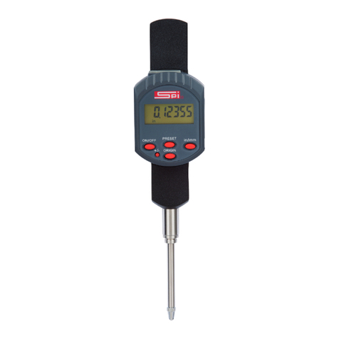
IP65 DIGITAL INDICATORS
swissprec.com
1
Battery holder
12
SET mode icon
2
Data output Port
13
Out of lower tolerance icon
3
Stem
14
Within tolerance icon
4
Flat back
15
Out of upper tolerance icon
5
Contact point
16
TOL mode icon
6
Spindle
17
mm/INCH icon
7
LCD
18
MAX /MIN mode icon
8
Mode Button
19
ABS/INC icon
9
SET Button
20
Plus/Minus icon
10
ZERO/ON/OFF
21
Measuring direction icon
11
Low battery icon
IP65 DIGITAL INDICATORS
OPERATION MANUAL
SPI 40G03
IMPORTANT NOTICE
•Clean all measuring surfaces and
body prior to use.
•Clean the battery before
installation.
•Zero set the tooling after installing
the battery.
Technical Specifications
•Resolution: Inch: .0005”/.00005”,Metric: 0.01mm/0.001mm
•Power: One silver oxide battery CR2032, 3V
•Protection class IP65.
•Working temperature: 0~ +40 ℃
•Relative humidity: <80%
•Storage temperature: -10℃~ +60℃
•Contact point: carbide ball (#4-48UNF).
Operation
➢Zero Setting
•When in ABS mode, press Zero/On.
•The displayed value will change to zero unless a preset value
has been established.
➢Absolute and Incremental Modes
•Absolute Mode: The absolute mode indicates that the
measurement is to the zero that has been previously set.
•Incremental Mode: The incremental mode is provided as a
temporary zero at any point within the measuring range. The
Absolute zero previously set will be restored when the mode is
returned to absolute.
•Switching between ABS and INC Modes
Short press the [SET] button to change the display to “INC”
(Incremental Mode). The reading will change to zero.
•Short press the [SET] button again to return to “ABS” (Absolute
Mode). The reading will be returned to the original value.
IP65 DIGITAL INDICATORS
swissprec.com
➢Switching between Mode Options
•Long press of [SET Button] to select tolerance function.
•Short press of [ZERO Button] to select Calibration Function.
•Short press of [ZERO Button] to select Metric/Inch measurement unit.
•Short press of [ZERO Button] to select measurement Direction.
➢Setting tolerance parameters
•Long press of [SET Button] to select tolerance function.
•Short press the [MODE Button] causing the right arrow to flash and the right digit will
flash.
•Short press the [ZERO Button] to choose the next digit to the left. Repeat step 3 to
select the correct digit. Continue until the lower tolerance value and sign is correct.
•Short press the [ZERO Button] to choose the next digit to the left. Repeat step 3 to
select the correct digit. Continue until the lower tolerance value and sign is correct.
•Short press the [SET Button] to change to the upper tolerance. The upper tolerance
icon will flash along with the last digit.
•Short press the [ZERO Button] to choose the next digit to the left. Repeat step 3 to
select the correct digit. Continue until the upper tolerance value and sign is correct.
•For this example: Lower Tolerance 6.000mm Upper Tolerance 6.200mm
➢Setting a preset value:
•Long press the [SET Button] and then Short press the [ZERO Button] to select the CAL
function.
•Short press the [MODE Button] and the last digit in the display will flash.
•Short press the [MODE Button] to index the flashing digit to required preset value
•Short press the [ZERO Button] to choose the next digit to the left. Repeat step 3 to
select the correct digit. Continue until the lower tolerance value and sign is correct
•Short press the [SET Button] to quit the preset function. The preset value will be
loaded by pressing the [ZERO Button] provided that the ABS mode is selected
•Long press the [ZERO Button] to remove a previously stored preset while in the CAL
mod
➢Change Display Sign
•Long press the [SET Button], and then Short press the [ZERO Button] to index the
menu to dir.
•Short press the [MODE button] to index the flashing display between the plus and
minus for inward movement of the spindle
•Short press the [SET Button] when the desired unit is flashing. Press the [Set button]
to return to measurement mode
➢MAX/MIN Function
•MAX mode: Press the [MODE Button] until MAX is displayed. The maximum spindle
movement value will be displayed. Use the [MODE Button] to exit from the MAX
mode.
•MIN mode: Press the [MODE Button] until MAX is displayed. Press the [SET Button]
to index to MIN mode. The minimum spindle movement value will be displayed. Use
the [MODE Button] to exit from the MIN mode.
•Press the [SET Button] after collecting the MAX and MIN datum and the difference
between the MAX and MIN values will be displayed. Use the [MODE button] to exit
from the max mode.
Low battery warning
The digits within the display will fade or flash as the battery voltage diminishes.
Upon total battery discharge the display will fail to be displayed. Please replace the
battery if any of the aforementioned conditions are applicable.
Other SPI Measuring Instrument manuals

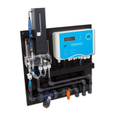
SPI C170 CHLORINE User manual

SPI

SPI C170 CHLORINE User manual

SPI DIAL CALIPER User manual

SPI

SPI DIAL CALIPER User manual

SPI 20-186-3 User manual

SPI

SPI 20-186-3 User manual

SPI D141 User manual

SPI

SPI D141 User manual

SPI 94200 Instruction Manual

SPI

SPI 94200 Instruction Manual

SPI 10-702-9 User manual

SPI

SPI 10-702-9 User manual

SPI Ground Gard Traveler Operating instructions

SPI

SPI Ground Gard Traveler Operating instructions

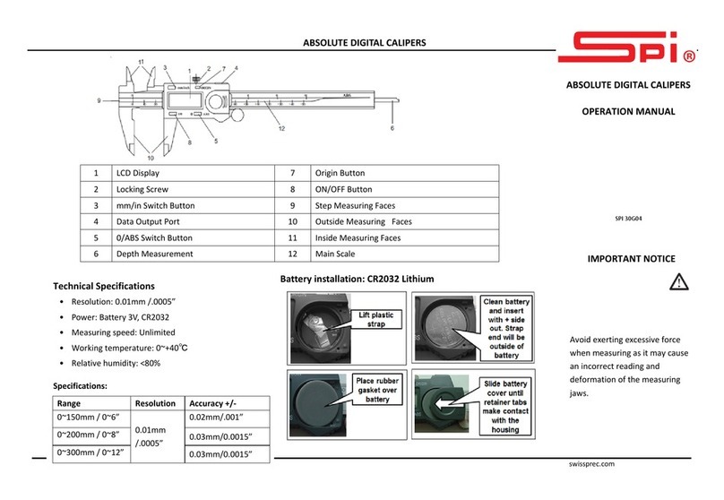
SPI ABSOLUTE DIGITAL CALIPER User manual

SPI

SPI ABSOLUTE DIGITAL CALIPER User manual

SPI 18-010-9 User manual

SPI

SPI 18-010-9 User manual

SPI SPI-P170 User manual

SPI

SPI SPI-P170 User manual

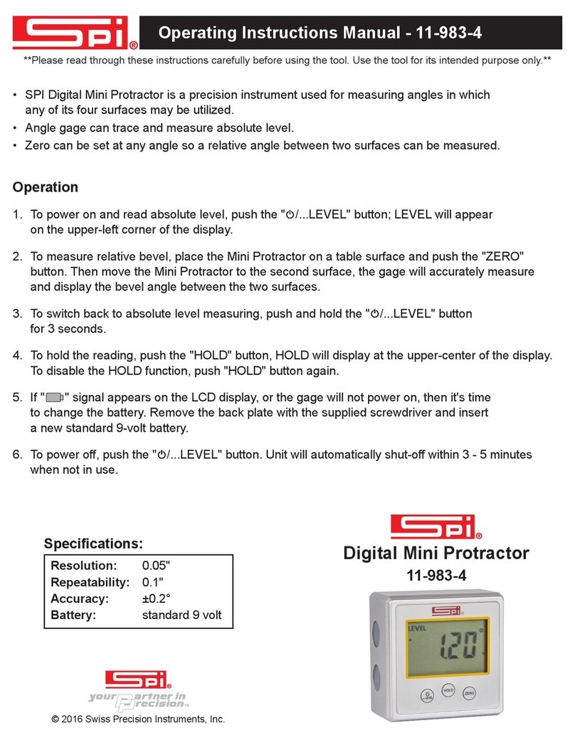
SPI 11-983-4 Instruction Manual

SPI

SPI 11-983-4 Instruction Manual

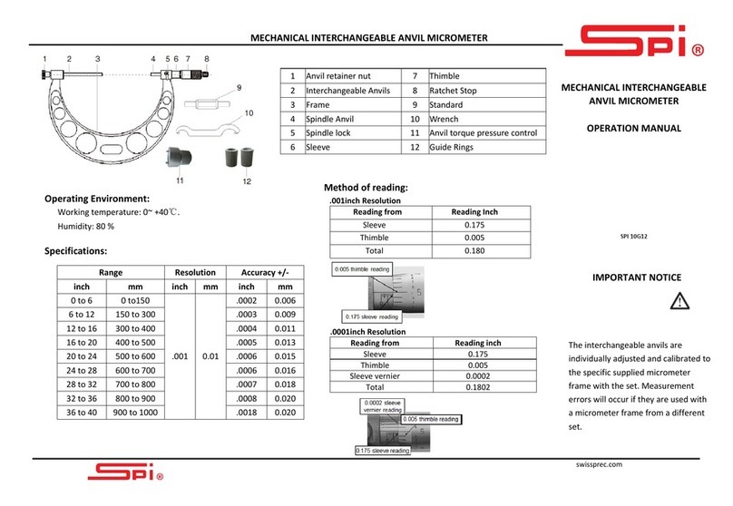
SPI 10G12 User manual

SPI

SPI 10G12 User manual

Popular Measuring Instrument manuals by other brands

Lechler Pocketwind IV user manual

Lechler

Lechler Pocketwind IV user manual

ARMANO RCh series Operating	 instruction

ARMANO

ARMANO RCh series Operating instruction

Blue-White F-461 instruction manual

Blue-White

Blue-White F-461 instruction manual

UEi C161 instruction manual

UEi

UEi C161 instruction manual

Agilent Technologies E8362A Service guide

Agilent Technologies

Agilent Technologies E8362A Service guide

Microchip Technology CAN Bus Analyzer user guide

Microchip Technology

Microchip Technology CAN Bus Analyzer user guide

peret FLUO instruction manual

peret

peret FLUO instruction manual

Downeaster Wind & Weather Medallion Series instruction manual

Downeaster

Downeaster Wind & Weather Medallion Series instruction manual

Sonel CMP-401 user manual

Sonel

Sonel CMP-401 user manual

Kapro prolaser 891 user manual

Kapro

Kapro prolaser 891 user manual

MSR 145 user manual

MSR

MSR 145 user manual

Fluke 82RF instruction sheet

Fluke

Fluke 82RF instruction sheet

Wagner Electronics L610 owner's manual

Wagner Electronics

Wagner Electronics L610 owner's manual

Haglof DP II user manual

Haglof

Haglof DP II user manual

hecht 2003 TRANSLATION OF ORIGINAL INSTRUCTIONS FOR USE

hecht

hecht 2003 TRANSLATION OF ORIGINAL INSTRUCTIONS FOR USE

Veto DF68D user guide

Veto

Veto DF68D user guide

CEM ORACLE manual

CEM

CEM ORACLE manual

TANEL Electronics WIP-22D user manual

TANEL Electronics

TANEL Electronics WIP-22D user manual

manuals.online logo
manuals.online logoBrands
  • About & Mission
  • Contact us
  • Privacy Policy
  • Terms and Conditions

Copyright 2025 Manuals.Online. All Rights Reserved.