DR. BENDER SQUATINA User manual

DR. BENDER GmbH
Innovative Power Tools
Operating Manual SQUATINA
Sawing accessories KOGIA
HF III ESPADA
Issued 10.2018 Art. No. 102255 ESPADA Subject to change
Art. No. 102249 KOGIA
Art. No. 102248 SQUARTINA
Art. No. 102251 SQUARTINA B
Alle Rechte vorbehalten / All rights reserved
DR. BENDER GmbH • D-75382 Althengstett • Tel 07051-9291-0 • Fax 07051-9291-91
We are on the internet at http://www.dr-bender.de • email: info@dr-bender.de

2
Contents
Page
Contents
2
1.0
Symbol and pictogram description
3
1.1
Function description
5
2.0
General instructions
6
2.1
Technical description
6
2.2
Applications
6
3.0
Transport and storage
6
3.1
Transport
6
3.2
Storage
6
4.0
Main dimensions and technical data
7
4.1
Dimensions
7
4.1.1
Squatina Full blade guard attachment
7
4.1.2
Squatina Flush cut blade guard attachment
7
4.1.3
Kogia attachment
8
4.1.4
Espada attachment
8
4.2
Technical data
9
4.2.1
Squatina full blade guard attachment
9
4.2.2
Squatina flush cut blade guard attachment
9
4.2.3
Kogia attachment
9
4.2.4
Espada attachment
9
5.0
Commissioning
10
5.1
Squatina full blade guard attachment
10
5.1.1
Saw blade change
10
5.2
Squatina flush cut blade guard attachment
10
5.2.1
Saw blade change
10
5.3
Kogia attachment
11
5.3.1
Ring saw blade change / adjustment
11
5.3.2
Fitting the optional guide plate
13
5.4
Espada attachment
14
5.4.1
Chain / blade change
14
5.5
Saw blades
14
5.6
Cutting speed when sawing
15
6.0
Warranty
15
7.0
General Safety Instructions
15
8.0
Spare parts lists
16
8.1
Squatina full blade guard attachment
16
8.2
Squatina flush cut blade guard attachment
18
8.3
Kogia attachment
20
8.4
Espada attachment
22

3
Attention
The safety instructions included in this operating manual must be followed!
Custom models and design variants may deviate from the basic type in
technical details. In the event of any discrepancies, we recommend that you
contact DR.BENDER GmbH urgently. Always state the machine type and the
machine number in any correspondence.
1.0 Symbol and pictogram description
Warning
Indicates instructions which may endanger your health or the functionality of the unit if
they are not followed. The warranty shall become null and void if you cause defects to
the unit by non-compliance with these instructions.
Recycling
Please direct waste to recycling.
Disposal
The customary and regional laws shall be observed for disposal.

4
Safety signs on the machine
Wear safety shoes
Wear gloves
Wear a safety helmet
Wear protective goggles
Wear ear protection
Wear a breathing mask
Pull the power plug before work on the device
Read the instructions

5
1.1 Function description
Chain saw ESPADA
Ring saw KOGIA
Squatina saw flush cut
blade guard
Squatina saw full blade
guard
Friction wheel
adjustment screw
Chain tension
adjustment screw
Blade
Ring saw blade
Chain
Saw blade for
flush cutting
Saw blade
Machine socket quick
release system

6
2.0 General instructions
2.1 Technical description
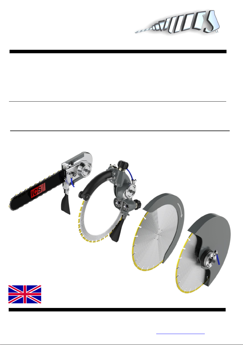
The BELUGA, SQUATINA, KOGIA and the ESPADA represent a whole new generation of drive units for
stone cutting. The exceptionally comprehensive modular system offers the flexibility needed today when
performing cutting work in concrete and stone. To achieve this, newly developed high-frequency motor
parts are used in the motor. The frequency range is controlled by the frequency converter from 0 - 1000 Hz
integrated into the Powerbox. The Powerbox can be operated on a single-phase 230 V mains supply as
well as on a 400 V mains supply with up to 12 kW. Our motors automatically detect the correct voltage and
then work at the allowed power rating for the voltage. At 1000 Hz, the rotor reaches a speed of 30.000 min-
1. A major benefit lies in the exceptional weight / power ratio (motor power output = 8 kW / weight = 12.5 kg
-> 0.64). Using conventional technology e.g. type BBM33extra (motor power output = 2.4 kW / weight =
13.5 kg -> 0.17). This means that the weight of the machine has been reduced fourfold using the high-
frequency technology. Further benefits lie in the stepless speed control. This enables the best speed to be
assigned to each tool diameter in order to attain the best possible cutting speed on the tool. During work,
the speed can be steplessly reduced if you come up against steel reinforcements and thus can be opti-
mised according to the progress of the work. Here, you can run the unit at much higher cutting speeds (At-
tention! depends on the tool) and in doing so, the progress of the job can be speeded up by up to 200 %.
With conventional machines, the torque drops very sharply at the higher speeds and therefore, this ad-
vantage does not apply here.
2.2 Applications
All attachments can be used with drive units, which are fitted with the DR. BENDER quick release system.
If you are using custom-built machines, the details on the quotation and the order confirmation also apply.
When suitable saw blades and drill bits are used, a wide range of materials can be cut:
- Concrete (even with strong reinforcement)
- Sandstone and limestone
- All building materials for solid walls
- Asphalt road surfacing
3.0 Transport and storage
3.1 Transport
Warning
The attachments must be inspected for transport damage after receipt. Any
damage present must be recorded in writing.
3.2 Storage
The storage location should be dry, clean, and at a constant temperature wherever possible. To keep the
lubrication film in the bearings and the seal systems from separating, the drive shaft should be turned
several times manually after a lengthy storage period, e.g. at monthly intervals. The roller bearings of the
devices should be replaced (or re-lubricated) if the period between delivery and commissioning is more
than 4 years. This period will be significantly reduced if the storage conditions are unsuitable.

7
4.0 Main dimensions and technical data
4.1 Dimensions
4.1.1 Squatina Full blade guard attachment
4.2.1 Squatina flush cut blade guard attachment

8
4.1.3 KOGIA attachment
4.1.4 ESPADA attachment

9
4.2 Technical data
4.2.1 SQUATINA full blade guard attachment
Maximum saw blade diameter
400
mm
Cooling medium Air / Water -
Saw blade holder diameter 1 (25.4 mm) “
Max. depth of cut 170 mm
Weight 4.6 kg
4.2.2 SQUATINA flush cut blade guard attachment
Maximum saw blade diameter 400
Cooling medium Air / Water -
Saw blade holder diameter 1 (25.4 mm) “
Pitch diameter for fastener countersunk holes 60 (6x60° M6) mm
Max. depth of cut 170 mm
Weight 4.5 kg
4.2.3 KOGIA attachment
Maximum ring saw blade diameter
400
mm
Cooling medium Water -
Max. depth of cut 300 mm
Weight 5.0 kg
4.2.4 ESPADA attachment
Blade length 380 mm
Cooling medium Water -
Max. depth of cut 380 mm
Weight 5.2 kg

10
5.0 Commissioning
5.1 SQUATINA Full blade guard attachment
5.1.1 Saw blade change
Remove the hex screw of the saw flange by turning it
clockwise. Attention, the screw has a left-hand thread.
Remove the top half of the flange with the matching
washer.
Insert the blade into the guard and plug it onto the output
spindle fitting. Always thoroughly grease the saw blade
hole and the output spindle as well as the hex screw.
Place the top half of the flange with the
matching washer onto the saw blade and
make sure that the flange half engages the output
spindle. Attach the hex screw and tighten by turning
anticlockwise. To tighten the hex screw with a SW17
spanner, you must hold the output spindle at the same
time with an SW27 spanner.
5.2 SQUATINA Flush cut blade guard attachment
5.2.1 Saw blade change
Proceed as described above in 5.1.1, but loosen or tighten the 6 hex socket countersunk head screws
instead of the centred left hand thread screw.

11
5.3 KOGIA attachment
5.3.1 Ring saw blade change / adjustment
1. Remove the ring saw blade from the friction
wheel / clamp.
Fully release the clamping nut (item 39) by
turning anticlockwise in order to remove the ring
saw blade from the friction roller.
To clamp the ring saw blade, the two
clamping nuts must be tightened
equally by turning them clockwise as
far as possible. The spring pressure must be set
so that the rollers automatically reset up to the
depth of wear of the ring saw blade.
2. Unhook / lift the support rollers.
Loosen the hex nut (item 67) with the SW 13
box spanner and tighten it again slightly. Turn
the adjustment sleeve (item 75) approx 8-9 turns
to the left to unhook the support rollers from the
ring saw blade by approx. 2 mm.
When fitting the support rollers, put the
hex nut (item 67) back on slightly.
Using the adjustment sleeve (item 75),
put the roller onto the ring saw blade by turning
it clockwise. The clamping roller may never be
set onto the ring saw blade with too high a
contact pressure. With the ring saw blade
stationary, it must be possible to turn it by hand.
Now tighten the hex nut (item 67).
3. Loosen the front cover
Loosen the 3 raised head screws (item 82 and
item 83) with an SW 4 Allen key. Remove the
front cover (item 81)
901221 raised head
screw
item 82
801379 raised head screw
i
tem 83
30177 Front cover item
81
401802 adjustment
sleeve
item 75
801889 Hex nut Item 67
301625 Clamping nut
Item 39

12
4. Replace the friction wheel
Loosen both Allen head screws with the SW 13
Allen key (item 79). To do so, lock the two-hole
spanner (item 95) on the flange to hold it down.
If the friction wheel is worn, it must be
replaced. Only use original spare
parts. Please ask your dealer.
5. Replace the ring saw blade.
The ring saw blade must not be
replated with diamond segments. Only
use original ring saw blades. Please
ask your dealer.
When inserting the ring saw blade,
make sure that the three raised edges
engage into the three grooves of the
ring saw blade.
6. Loosen the support and the guide rollers
Using a swan neck SW 17 box spanner, tighten the
hex washer (item 64 / 45) Loosen both Allen head
screws with the SW 5 Allen key (item 66)
When reinserting the raised head flange
screw, use medium strength Loctite.
900227 Washer
item 65
802491 Allen head screw item 66
401731 Hex washer item
64
102182 Ring saw
blade
item 3
301621 Friction
wheel item 76
901299 Allen head screw item
79
401800 Flange item 77
800075 Lock washer item 78
901299 Allen head screw
item 79
802687 two-hole spanner
item 95

13
7. Replace the support and the guide rollers
Loosen the support rollers (item 63) and the guide
rollers (item 44).
The edges of the rollers that engage the
ring saw blade must be sharp. If this is
not the case, they must be replaced.
5.3.2 Fitting the optional guide plate
Remove the front cover (item 81), see
5.3.1 item 3.
Replace the two distance bushes (item
80) through the complete guide plate
(item 94).
402007 Distance
bushes
Item 80
302426 complete guide roller
Item 94
301533 support roller
Item 63
301528 Guide roller
Item 44

14
5.4 ESPADA attachment
5.4.1 Chain / blade change
Remove the side guard by loosening the two wing screws (1) on the console.
Loosen the hex nut (2) in the centre of the console until it can be turned by hand.
Turn the clamping screw (3) anticlockwise until the blade bears against
the drive wheel.
The old chain can now be removed from the blade tip.
When pulling on the new chain, make sure that the chain is first placed
around the drive wheel, then into the guide groove towards the blade tip.
The blade is now tensioned by turning the clamping screw (3)
clockwise. The chain tension should be set so that the chain is
taut but can still be moved by hand.
Tighten the hex nut (2) again.
The guard can then be pushed on again and fastened with wing screws
(1). Make sure that the plastic washers of the wing screws are not clamped between guard and console.
First remove the chain as described in 5.4.1.
Remove the hex nut (2) completely and pull the holding
plate from the blade.
The blade can now be easily removed from the console.
Place the new blade into the console. Make sure that the
clamping pins (4) are guided into the holes provided on the
blade.
Now insert the holding plate through the oval hole of the blade and insert the hex nut again (2), attach it by
hand.
Move the chain to insert and tension it as described in 5.4.1.
5.5 Saw blades
You can use any saw blade with a connection bore of 1 “ ( 25.4 mm) . Only use saw blades which are
suitable for the stone type. Using only concentric saw blades that are not deformed prolongs the service life
of the drive unit. Ensure that the diamond segments have an adequate undercut in relation to the saw
blade.

15
5.6 Cutting speed when sawing
The Squatina 400 may operate with a max. saw blade Ø of 400 mm
Saw
blade Ø
Squatina 400
with SXM V
2830 min-1
300 mm
45 m/s
350 mm
52 m/s
400 mm
60 m/s
The Kogia 400 may operate with a max. ring saw blade Ø of 400 mm
Saw
blade Ø
Kogia
with SXM V
2025 min-1
400 mm
43 m/s
The Espada can be operated with various blade and chain lengths.
Blade
chain
length
Espada
with SXM V
5120 min-1
380 mm
22 m/s
480 mm
22 m/s
600 mm
22 m/s
6.0 Warranty
Pursuant to our Terms & Conditions of Sale, we offer a warranty of 12 months from the date of purchase.
This covers the free repair of material and production defects shown to have been caused prior to sale.
An original sales receipt must always be produced when asserting a warranty claim. It must include the full
address of the dealer, purchase date, and type code of the product. The user manual for the relevant prod-
uct as well as the safety instructions must have been followed.
Damage caused by operating errors is not covered by the warranty.
The manufacturer’s products are developed and built for specific applications. If the product is used for
purposes other than the intended purpose based on the user manual, or in the event of misuse, or if unap-
proved accessories are used, the warranty shall become null and void.
The products must be regularly maintained and cleaned according to the instructions in the user manual.
The warranty shall become null and void in the event of an intervention by third parties (opening the ma-
chine).
The warranty does not cover maintenance and cleaning work.
You must ensure that only original spare parts and accessories are used. The products must be purchased
from an authorised dealer. If non-original parts are used, this may result in consequential damage and in-
creased risk of accidents. The manufacturer is not liable for such damage. Disassembled, partially disas-
sembled units and units repaired with third party parts are not covered by the warranty.
Certain parts are subject to normal wear and tear depending on use. These parts include e.g. carbon
brushes, ball bearings, switches, mains cables, seals, etc. These consumable parts are not covered by the
warranty. Consumable parts are highlighted in the spare parts lists.
7.0 General Safety Instructions
The general safety instructions can be found in the supplied safety instruction booklet.

16
8.0 Spare parts lists
8.1 SQUATINA Full blade guard attachment

17
Item
Part no.
Description
No.
1
102248
Attachment SQUATINA 400 complete
1
2
101353
Guard complete
1
3
100276
Guard
1
4
401452
Hub
1
5
900302
Allen head screw
1
6
901126
Hex socket countersunk head screw
4
7
301705
Rotor WSS
1
8
102194
Rotor housing
1
9
900000
Groove ball bearing
1 **
10
801368
Snap ring
1
11
802418
Rotary shaft seal
2 **
12
900795
Snap ring
1
13
301761
Spindle complete
1
14
301704
Spindle
1
15
401668
Bushing
1
16
401853
Shaft sleeve
1
17
901116
Rotary shaft seal
1 **
18
900202
Snap ring
1
19
301244
Flange
2
20
902076
Washer
1
21
901041
Hex screw
1
22
301522
Flange
1
23
900688
Allen head screw
4
24
802402
Threaded nipple
1
25
802403
Water hose
1 **
26
302042
Saw blade
1 **
Wearing parts **

18
8.2 SQUATINA Flush cut blade guard attachment

19
Item
Part no.
Description
No.
1
102251
Attachment Squatina 400 flush cut complete
1
2
101757
Guard complete
1
3
102372
Guard
1
4
401452
Hub
1
5
900302
Allen head screw
1
6
901126
Hex socket countersunk head screw
4
7
301703
Rotor WS BS
1
8
102194
Rotor housing
1
9
900000
Groove ball bearing
1 **
10
800559
Snap ring
1
11
802418
Rotary shaft seal
2 **
12
900795
Snap ring
1
13
301762
Spindle complete
1
14
301702
Spindle
1
15
401668
Bushing
1
16
401853
Shaft sleeve
1
17
901116
Rotary shaft seal
1 **
18
900202
Snap ring
1
19
301307
Flange
1
20
301522
Flange
1
21
401605
Washer
1
22
901065
Hex socket countersunk head screw
1
23
900688
Allen head screw
4
24
802402
Threaded nipple
1
25
802513
Water hose
1 **
26
901019
Allen head screw
6 **
27
302041
Saw blade
1 **
Wearing parts **

20
8.3 KOGIA attachment
This manual suits for next models
7
Table of contents
Other DR. BENDER Power Tools Accessories manuals
Popular Power Tools Accessories manuals by other brands

STEINEL PROFESSIONAL
STEINEL PROFESSIONAL 4007841009595 quick start guide

Dynabrade
Dynabrade 61374 operating instructions

SCHUNK
SCHUNK ROTA TB-TBS-EP Assembly and operating manual

RiveDrill
RiveDrill HP Instructions for use

TREND
TREND HR/JIG instruction manual

Powerfix Profi
Powerfix Profi Z31280 Assembly, operating and safety instructions