Dräger Polytron 5000 User manual

Docking Station for Ex e version of
Polytron® 5000/8000
Assembly instructions
enUS · de · fr · es · bg · cs · da · el · et · fi · hr · hu · it · lt · lv · nl · no · pl · ptBR · ro · ru · sk · sl · sv · tr · zh

enUS Assembly instructions.............................................................8
de Montageanweisung...............................................................13
fr Notice de montage................................................................18
es Instrucciones de montaje......................................................23
bg Инструкция за монтаж ........................................................28
cs Montážní návod ....................................................................33
da Monteringsvejledning............................................................38
el Οδηγίες τοποθέτησης ...........................................................43
et Paigaldusjuhend ...................................................................48
fi Asennusohje .........................................................................53
hr Uputa za montažu.................................................................58
hu Összeszerelési útmutató ......................................................63
it Istruzioni di montaggio..........................................................68
lt Montavimo instrukcija ...........................................................73
lv Montāžas instrukcija .............................................................78
nl Montage-instructie ................................................................83
no Monteringsanvisning.............................................................88
pl Instrukcja montażu................................................................93
ptBR Instruções de montagem ......................................................98
ro Instrucţiuni de montaj..........................................................103
ru Инструкция по сборке.......................................................108
sk Návod na montáž................................................................113
sl Navodila za sestavljanje .....................................................118
sv Monteringsanvisning...........................................................123
tr Montaj ve kurulum kılavuzu ................................................127
zh 安装说明 .............................................................................132
Docking Station for Ex e version of Polytron® 5000/8000

36808
A2
1
2
3
red (+)
black (-)
brown (4-20mA)
(4-20mA)
-
+
12 3
1 2 3
~12 mm
~45 mm
ab
cd
AA1
B C
Without relay:

36809
PWR+
PWR-
PWR-
4-20 mA
PE
VDC
+
-
mA
4-20 mA / HART (Current source)
Analog, relay
PWR+
PWR-
PWR-
4-20 mA
PE
Stand-alone, relay only
VDC
+
-
4-20 mA / HART (Current sink)
PWR+
PWR-
PWR-
4-20 mA
PE
VDC
+
-
4-20 mA / HART (separate power supply)
mA
PWR+
PWR-
PWR-
4-20 mA
PE
VDC
+
-
mA
D4
D3
D2
Common
Normally Open
PE
4-20 mA
PWR-
PWR-
PWR+
D1
D2
D3
D4
A1
A2
FAULT
PE
D
D1

36810
PWR+
PWR-
SCR
Digital: Fieldbus FF / Profibus PA, Modbus RTU
Power
VDC
+
-
FIELDBUS (X2)
PWR+
PWR-
SCR
E1
FB+
FB-
COM
SCR
E2
E3
E2 Fieldbus FF / Profibus PA
E3 Modbus RTU
FB +
FB -
COM
SCR
FB +
FB -
COM
SCR
FB+ / Data A
FB- / Data B
+ / Data A
- / Data B
Ground
E
E1

36896
S1 / PE
S2 / 5
S3 / 4
S4 / 2
S5 / 1
F2
F F2
PIR 7x00
F1
Field wiring
PIR 7x00 + Docking Station
C1
C1
S1S1
S2S2
S3S3
S4S4
S5S5
PE YellowPE Yellow
5 White5 White
4 Brown4 Brown
2 Black2 Black
1 Red1 Red
S1 S3 S5S1 S3 S5
S2 S4S2 S4
7
POWER FAULT
7
POWER FAULT
44 5533
22
11 PEPE
RR BLKBLK BRBR WW YY

36807
GG2
DD, DQ, LC
DSIR
G1
3 - core field wiring
(Sensors: DSIR, DD, DQ, LC)
5 - core field wiring
(Sensors: DSIR, DD, DQ, LC)
Ferrit (Sensors: DD, DQ, LC)
C1
C2
2
1
1
G4
C1
G3
C1
S2 S4S2 S4
S1 S3 S5S1 S3 S5
S2 S4S2 S4
S1 S3 S5S1 S3 S5
3
2
1
3
2
1
BLKBLK
Y
BRBR
BLKBLK
Y
BRBR
G4G4

8 Assembly instructions | Docking Station for Ex e version of Polytron® 5000/8000
en | Safety information
Docking Station for Ex e version of Polytron® 5000/8000
1 Safety information
Any use of the Docking Station for the e-version of Polytron1) 5xx0/8xx0
requires full understanding and strict observance of the instructions for use of
the respective Dräger Polytron instrument (e. g. Dräger Polytron 5000/8000
instructions for use).
2 Conventions in this document
2.1 Meaning of the warning notes
The following warning signs are used in this document to indicate and highlight
areas of the associated text that require particular attention by the user. A
definition of the meaning of each sign is as follows:
3 Functional description
The Docking Station is required for the electrical installation in any area with an
"increased safety" explosion protection rating.
● Instrument for increased safety (Ex e)
The instrument is extended by an increased safety terminal box (docking
station) that provides up to four 20 mm openings, which can be used for field
wiring or wiring of a remote sensor. The permissible cable diameter range is
7 to 12 mm.
The Docking Station can be pre-mounted, wired and sealed with the supplied
cover. Once the site is ready for commissioning, the instrument is then hooked
up to the Docking Station and taken into operation; avoiding that the instrument
is damaged during the construction phase.
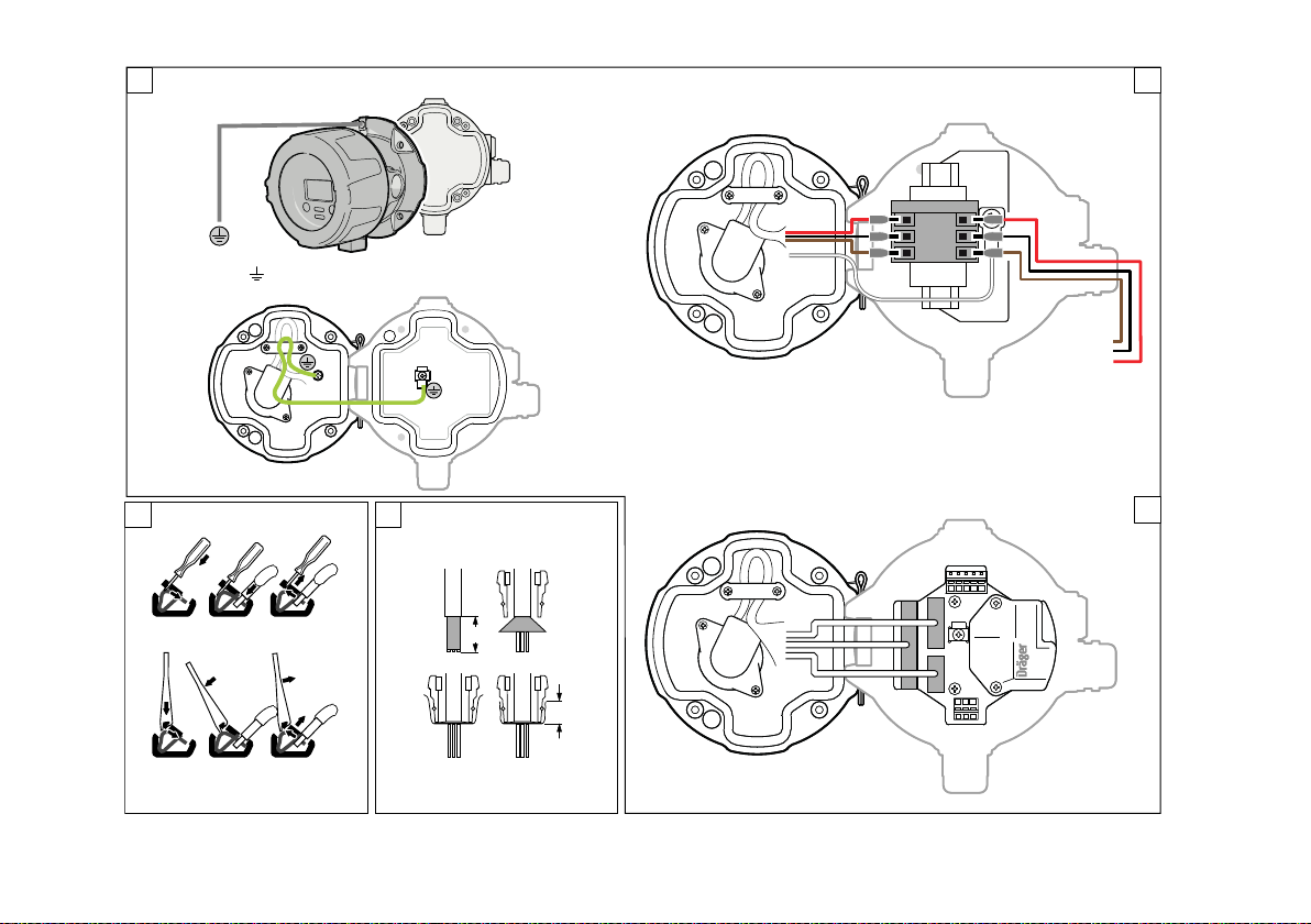
The connection between the Docking Station and the main instrument is
realized via a ‘feedthrough’. Depending on the instrument selected, there are 3
types of feed-through.
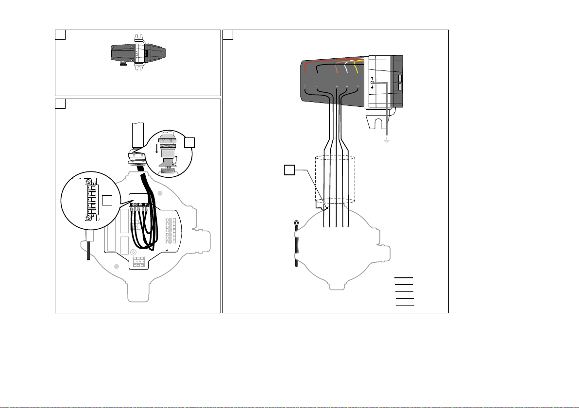
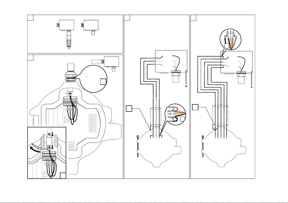
– feedthrough 3 wires for power
– feedthrough 9 wires for power and relay
– feedthrough 14 wires for power, interface connections or relay and remote
sensor (not for Polytron® 8100 EC)
4 Intended use
The Docking Station is intended for installation either in hazardous areas of
zone 1, 2 or 21, 22 according to device categories 2G, 3G or 2D, 3D.
The Docking Station is suitable for wall, ceiling and duct mounting.
Duct mounting requires additional mounting kits.
5 Assembly
The gas detector can be used to measure gases in the ambient air or in a
pipe/duct.
1. Attach the Docking Station to one of the following options.
1) Polytron® is a registered trademark of Dräger.
Alert icon Signal word Consequences in case of nonob-
servance
WARNING Indicates a potentially hazardous situa-
tion. If not avoided, it could result in
death or serious injury.
CAUTION Indicates a potentially hazardous situa-
tion. If not avoided, it could result in
physical injury. It may also be used to
warn against unsafe practices.
NOTICE Indicates a potentially hazardous situa-
tion. If not avoided, it could result in
damage to the product or environment.
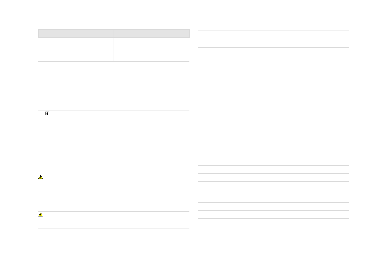
Option
Mounting on a flat surface Use a drilling template (part number
45 44 299) and attach it using 4
screws (M6 x 10).
Mounting to a bar or beam Mount kit (part number 45 44 198)

Installation | en
Assembly instructions | Docking Station for Ex e version of Polytron® 5000/8000 9
2. Pull the hinge pin out of the Docking Station.
3. Align the gas detector hinge with the Docking Station hinge and reinsert the
hinge pin.
The gas detector is attached and can be opened to gain access to the
wiring.
4. Connect the cable bushings of the gas detector to the Docking Station.
In the case of a cable bushing with stranded wires, observe the terminal
assignment .
The plug locks must engage.
5. Connect the ground wire to the ground connection (torque 1.2 Nm).
6. Wire the Docking Station as described in Installation chapter.
7. Check the electrical installation to ensure that all conductors are properly
connected.
8. Screw the gas detector onto the Docking Station with 4 screws and a torque
of 8 Nm (70 LB IN.). The 4 screws are included in the delivery (M6 1/4 "
hexagon socket head cap screws).
6 Installation
WARNING
The electrical installation must only be carried out by experts. During
installation, all wiring must conform to the relevant, applicable national
regulations relating to the installation of electrical equipment and, where
applicable, the regulations for installation in potentially explosive areas. In case
of any doubt, obtain the relevant information from the appropriate official body
before executing the installation.
CAUTION
Do not apply power before the electrical installation is complete and has been
checked. Do not pull on cables to unplug!
NOTICE
For installation of the conductors onto the terminal block, a screwdriver or the
special enclosed tool is required.
Observe the following during installation:
– When installing at locations exceeding ambient temperatures of 55 °C
(149 °F), use only appropriate wiring specified for at least 25 K above the
maximum ambient temperature.
– Strip wire insulation by 5-7 mm (0.2 - 0.25“).
– Minimum wire size:
– Polytron SE EX sensing heads: 0.7 mm2 (AWG 21).
– Relay connection: 1 mm2 (AWG 18)
– Limitations for daisy-chaining gas transmitters (HART multi-drop): 2 flexible
wires, wire size 1 mm2 (crimped together with ferrule within a cage clamp).
– For remote installations, the maximum permissible distance between the
gas detector and the sensors is 30 m (100 ft).
– For the fieldbus version, only shielded cables may be used.
6.1 Terminal assignment
6.1.1 Version: Cable bushing with stranded wires, Figure A1
Power supply and signal output only
Terminal block for power supply and analog signals
Only for Polytron 5100 EC:
Terminal block for power supply for 2-wire installation
Mounting in a tube/duct Duct mount kit (part number
68 12 725)
For Polytron® 57x0 IR / 87x0 IR Part
number: 68 12 300
Option
Terminal 1 2 3
Assignment + - 4-20 mA signal
Terminal 1 2 3
Assignment ± open 4-20 mA signal

10 Assembly instructions | Docking Station for Ex e version of Polytron® 5000/8000
en | Installation
6.1.2 Version: Cable bushing with plugs, Figure A2
Power supply, connection of sensing heads, relay, digital or analog signals
Terminal block for power supply and analog signals, Figure D
Terminal block for relays, Figure D
The outputs of the relay terminal are factory-set to normally open (NO) and
common (COM).
Terminal block for connecting sensing heads, Figures F and G
Terminal block for power supply of fieldbus connection, Figure E1
Terminal for Modbus RTU connection, Figures E2
Terminal 1 2 3 4 5
Assignment + - - 4-20 mA
signal
PE
Terminal 1 2 3 4 5 6 7
Assign-
ment
Fault Fault Alarm
2
Alarm
2
Alarm
1
Alarm 1 PE
Terminal1) 1 2 3 4 5
Dräger PIR 7000 Type 334
(M25) complete set 6811825
Green/
yellow
White Brow
n
Black Red
Dräger PIR 7000 Type 340
(M25) complete set 6811819
Dräger PIR 7200 (M25)
complete set 6812290
Sensing Head Polytron SE
Ex PR M1 DD/DQ 6812711
Black Bridge
terminal
2 with
terminal
12)
Yel-
low
Bridge
terminal
4 with
terminal
52)
Brow
n
Sensing Head Polytron SE
Ex PR M2 DD/DQ 6812710
Sensing Head Polytron SE
Ex HT M DD/DQ 6812720
Sensing Head Polytron SE
Ex LC M1 DD/DQ 6812722
Sensing Head Polytron SE
Ex LC M2 DD/DQ 6812721
Sensing Head DrägerSensor
IR, complete set e 6811165
Sensing Head DrägerSensor
IR, complete set e 6811265
1) The numbering of the terminal block on the Docking Station does not always correspond to the
numbering on the sensor or the complete set. The color coding is crucial.
2) The operator must ensure the correct version by using suitable cable cross-sections/ferrules.
Terminal PWR + PWR - SCR
Assignment Voltage + Voltage - Shield
Terminal FB + FB - COM SCR
Assignment Signal line
A
Signal line B Grounding Shield
Terminal1) 1 2 3 4 5

Installation | en
Assembly instructions | Docking Station for Ex e version of Polytron® 5000/8000 11
Terminal block for Foundation Fieldbus FF / PROFIBUS PA, Figures E3
6.2 Connecting field wiring to the Docking Station
Strip the cable shield and wire the terminals (Figure B and C)
1. Feed the cable (permissible diameter range: 7-12 mm) through the
respective cable entry (M20).
2. When using relays:
a. Remove the protective cover.
b. Connect the relay cable to the terminal block.
c. Refit the protective cover.
3. When connecting sensing heads with a catalytic sensor (DD, DQ, LC) Fold-
out page, Fig. C2:
a. Feed the cable cores through the supplied ferrite.
b. Position the ferrite between the cable sheath and the terminal block
Fold-out page, Fig. C2, step 1.
c. Attach a cable tie around the cable cores directly behind the ferrite Fold-
out page, Fig. C2, step 2.
4. Connect the cable cores to the respective terminal block. Observe the
terminal assignment and the figures.
5. Seal all unused cable entries on the Docking Station with approved plugs.
6. Make sure the cable cores are not squeezed and the seal is not impaired.
3-wire connection of sensing heads (Figure G2)
For connecting 3-wire cables, the Spare Parts Kit 8326496 is available (Fig.
G4).
6.3 Relay operation
The outputs of the relay terminal are factory-set to normally open (NO) and
common (COM).
NOTICE
If the default configuration for NO does not fit for the application, the wiring must
be changed at the relay terminals within the gas detector.
► To rewire the Alarm 1 relay, move the gray wire from A1NO to A1NC.
► To rewire the Alarm 2 relay, move the blue wire from A2NO to A2NC.
► To rewire the Fault relay, move the violet wire from FLTNO to FLTNC.
► The wires to A1COM, A2COM and FLTCOM should not be moved.
Terminal FB + FB - COM SCR
Assignment Signal lines
A
Signal lines
B
Not con-
nected
Shield
Connection Figure
4-20 mA A1
4-20 mA / HART D
Connected as current source D2
Connected as current sink D3
Connection of a separate current source D4
Relay operation D
Relay operation without 4-20 mA connection D, D1
Fieldbus E
Foundation Fieldbus FF / PROFIBUS PA connection E2
Modbus RTU connection E3
Power supply E1
Connection of PIR 7x00 F
Connection of sensing heads, 3-wire G1, G2
Connection of sensing heads, 5-wire G1, G3
Connection Figure

12 Assembly instructions | Docking Station for Ex e version of Polytron® 5000/8000
en | Disposal
7 Disposal
This product must not be disposed of as household waste. This is indi-
cated by the adjacent icon.
You can return this product to Dräger free of charge. For information
please contact the national marketing organisations and Dräger.

Sicherheitsbezogene Informationen | de
Montageanweisung | Docking Station for Ex e version of Polytron® 5000/8000 13
Docking Station for Ex e version of Polytron® 5000/8000
1 Sicherheitsbezogene Informationen
Jede Handhabung an der Docking Station für die e-Version Polytron1)
5xx0/8xx0 setzt die genaue Kenntnis und Beachtung der Gebrauchsanweisung
des entsprechenden Dräger Polytron-Geräts (z. B. Gebrauchsanweisung
Dräger Polytron 5000/8000) voraus.
2 Konventionen in diesem Dokument
2.1 Bedeutung der Warnhinweise
Die folgenden Warnzeichen werden in diesem Dokument verwendet, um die
zugehörigen Warntexte zu kennzeichnen und hervorzuheben, die eine erhöhte
Aufmerksamkeit seitens des Anwenders erfordern. Die Bedeutungen der
Warnzeichen sind wie folgt definiert:
3 Funktionsbeschreibung
Die Docking Station wird für die elektrische Installation mit der Zündschutzart
„Erhöhte Sicherheit“ benötigt.
● Gerät mit erhöhter Sicherheit (Ex e)
Das Gerät wird durch einen Klemmenkasten für erhöhte Sicherheit (Docking
Station) erweitert, der über bis zu vier 20-mm-Anschlüsse verfügt, die für die
Feldverdrahtung oder die Verdrahtung eines abgesetzten Sensors genutzt
werden können. Der zulässige Kabeldurchmesser beträgt 7 bis 12 mm.
Die Docking Station kann bereits ohne das Gasmessgerät montiert, verdrahtet
und mit dem mitgelieferten Vormontagedeckel verschlossen werden. Wenn die
Bauphase der Anlage abgeschlossen ist, wird das Gasmessgerät auf die
Docking Station montiert. Dies verhindert, dass das Gasmessgerät während der
Bauphase einer Anlage beschädigt wird.
Der Anschluss zwischen der Docking Station und dem Gasmessgerät erfolgt
über eine „Kabeldurchführung“. Je nach gewähltem Gasmessgerät stehen 3
Arten von Kabeldurchführungen zur Verfügung:
– Kabeldurchführung 3 Drähte für Stromversorgung
– Kabeldurchführung 9 Drähte für Stromversorgung und Relais
– Kabeldurchführung 14 Drähte für Stromversorgung, Feldbusverbindungen
oder Relais und abgesetzte Sensoren (nicht für Polytron® 8100 EC)
4 Verwendungszweck
Die Docking Station dient wahlweise zur Installation in Ex-Bereichen der Zone
1, 2 oder 21, 22 entsprechend der Gerätekategorie 2G, 3G oder 2D, 3D.
Die Docking Station ist zur Wand-, Decken- und Rohrmontage geeignet.
Zur Rohrmontage sind zusätzliche Anschlusssets erforderlich.
5 Montage
Das Gasmessgerät kann zum Messen von Gasen in Umgebungsluft oder in
einem Rohr/Lüftungskanal angebracht werden.
1. Die Docking Station an einer der folgenden Optionen anbringen.
1) Polytron® ist eine eingetragene Marke von Dräger.
Warnzeichen Signalwort Folgen bei Nichtbeachtung
WARNUNG Hinweis auf eine potenzielle Gefahrensi-
tuation. Wenn diese nicht vermieden
wird, können Tod oder schwere Verlet-
zungen eintreten.
VORSICHT Hinweis auf eine potenzielle Gefahrensi-
tuation. Wenn diese nicht vermieden
wird, können Verletzungen eintreten.
Kann auch als Warnung vor unsachge-
mäßem Gebrauch verwendet werden.
HINWEIS Hinweis auf eine potenzielle Gefahrensi-
tuation. Wenn diese nicht vermieden
wird, können Schädigungen am Produkt
oder der Umwelt eintreten.
Option
Montage auf flachem Untergrund Bohrschablone benutzen (Sachnum-
mer 45 44 299) und mit 4 Schrauben
(M6 x 10) befestigen.

14 Montageanweisung | Docking Station for Ex e version of Polytron® 5000/8000
de | Installation
2. Scharnierstift aus der Docking Station ziehen.
3. Scharnier des Gasmessgeräts zum Scharnier der Docking Station
ausrichten und den Scharnierstift wieder einsetzen.
Das Gasmessgerät ist befestigt und kann aufgeklappt werden, um
Zugang zur Verdrahtung zu erhalten.
4. Kabeldurchführungen des Gasmessgeräts an die Docking Station
anschließen.
Bei Kabeldurchführung mit Litzen, die Klemmenbelegung beachten .
Die Verriegelung der Stecker muss einrasten.
5. Masseleitung an Masseanschluss anschließen (Drehmoment 1,2 Nm).
6. Die Docking Station wie in Kapitel Installation beschrieben verdrahten.
7. Elektrische Installation überprüfen, um sicherzustellen, dass alle Leiter
richtig angeschlossen sind.
8. Das Gasmessgerät mit 4 Schrauben und einem Drehmoment von 8 Nm
(70 LB IN.) auf die Docking Station schrauben. Die 4 Schrauben sind Teil
des Lieferumfangs (M6 1/4"-Sechskant-Zylinderschrauben).
6 Installation
WARNUNG
Die elektrische Installation darf nur von Fachleuten durchgeführt werden. Bei
der Installation muss die gesamte Verdrahtung den jeweils geltenden
nationalen Vorschriften hinsichtlich der Installation elektrischer Geräte und ggf.
den Vorschriften für die Installation in explosionsgefährdeten Bereichen
entsprechen. Im Zweifelsfall vor Ausführung der Installation bei der offiziellen,
zuständigen Stelle nachfragen.
VORSICHT
Gerät nicht mit Strom versorgen, bevor die elektrische Installation
abgeschlossen und geprüft ist. Zum Lösen von Steckern nicht an den Kabeln
ziehen.
HINWEIS
Für die Installation der Leiter an den Klemmenblock wird ein Schraubendreher
oder das beiliegende Spezialwerkzeug benötigt.
Bei der Installation beachten:
– Ab 55 °C Umgebungstemperatur elektrische Leitungen verwenden, die
mindestens für Temperaturen über 25 K der maximal zu erwartenden
Umgebungstemperatur ausgelegt sind.
– Zu installierende Leitungen auf eine Länge von 5-7 mm abisolieren.
– Minimaler Leitungsquerschnitt:
– Polytron SE EX Messköpfe: 0,7 mm2 (AWG 21).
– Relaisanschluss: 1 mm2 (AWG 18)
– Beschränkungen für in Serie geschaltete Gastransmitter (HART Multidrop):
2 flexible Leitungen, Leitungsquerschnitt 1 mm2 (zusammen gecrimpt in
einer Aderendhülse).
– Bei Remote-Installationen darf der Abstand zwischen dem Gasmessgerät
und den Sensoren maximal 30 m betragen.
– Bei Feldbusausführung dürfen nur geschirmte Kabel verwendet werden.
6.1 Klemmenbelegung
6.1.1 Ausführung: Kabeldurchführung mit Litzen, Abbildung A1
Nur Stromversorgung und Signalausgang
Klemmblock für Stromversorgung und analoge Signale
Montage an einer Stange oder Balken Halterungsset (Sachnummer
45 44 198)
Montage in einem Rohr/Lüftungskanal Rohranschlussset (Sachnummer
68 12 725)
Für Polytron® 57x0 IR / 87x0 IR Sach-
nummer: 68 12 300
Option
Klemme 1 2 3
Belegung + - 4-20-mA-Signal

Installation | de
Montageanweisung | Docking Station for Ex e version of Polytron® 5000/8000 15
Nur für Polytron 5100 EC:
Klemmblock für Stromversorgung bei 2-Draht-Installation
6.1.2 Ausführung: Kabeldurchführung mit Steckern, Abbildung A2
Stromversorgung, Anschluss von Messköpfen, Relais, digitale oder analoge
Signale
Klemmblock für Stromversorgung und analoge Signale, Abbildungen D
Klemmblock für Relais, Abbildung D
Die Ausgänge der Relais-Klemme sind von Werk aus Normally Open (NO) und
Common (COM) geschaltet.
Klemmblock für den Anschluss von Messköpfen, Abbildungen F und G
Klemmblock für Stromversorgung Feldbusanschluss, Abbildungen E1
Klemmblock für Modbus RTU, Abbildungen E2
Klemme 1 2 3
Belegung ± offen 4-20-mA-Signal
Klemme 1 2 3 4 5
Belegung + - - 4-20-mA-
Signal
PE
Klemme 1 2 3 4 5 6 7
Belegung Fault Fault Alarm
2
Alarm
2
Alarm
1
Alarm
1
PE
Klemme1) 1 2 3 4 5
Dräger PIR 7000 Typ 334
(M25) Komplettset 6811825
Grün/
gelb
Weiß Braun Schwarz Rot
Dräger PIR 7000 Typ 340
(M25) Komplettset 6811819
Dräger PIR 7200 (M25)
Komplettset 6812290
Messkopf Polytron SE Ex
PR M1 DD/DQ 6812711
Schwarz Klemme
2 mit
Klemme
1 brü-
cken2)
Gelb Klemme
4 mit
Klemme
5 brü-
cken2)
Braun
Messkopf Polytron SE Ex
PR M2 DD/DQ 6812710
Messkopf Polytron SE Ex
HT M DD/DQ 6812720
Messkopf Polytron SE Ex LC
M1 DD/DQ 6812722
Messkopf Polytron SE Ex LC
M2 DD/DQ 6812721
Messkopf DrägerSensor IR,
Komplettset e 6811165
Messkopf DrägerSensor IR,
Komplettset e 6811265
1) Die Nummerierung des Klemmenblocks an der Docking Station entspricht nicht immer der Num-
merierung am Sensor oder dem Komplettset. Ausschlaggebend ist die Farbkennzeichnung.
2) Die korrekte Ausführung ist vom Betreiber durch Verwendung geeigneter Kabelquer-
schnitte/Aderendhülsen sicherzustellen.
Klemme PWR + PWR - SCR
Belegung Spannung + Spannung - Schirm
Klemme FB + FB - COM SCR
Belegung Signalfüh-
rung A
Signalfüh-
rung B
Erdung Schirm
Klemme1) 1 2 3 4 5

16 Montageanweisung | Docking Station for Ex e version of Polytron® 5000/8000
de | Installation
Klemmblock für Foundation Fieldbus FF / PROFIBUS PA, Abbildungen E3
6.2 Feldverdrahtung an die Docking Station anschließen
Kabelschirm abisolieren und Klemmen verdrahten (Abbildung B und C)
1. Kabel (zulässiger Durchmesser: 7-12 mm) durch die entsprechende
Kabeleinführung (M20) führen.
2. Bei der Verwendung von Relais:
a. Schutzabdeckung abnehmen.
b. Relaiskabel an Klemmenblock anschließen.
c. Schutzabdeckung wieder anbringen.
3. Beim Anschluss von Messköpfen mit katalytischem Sensor (DD, DQ, LC)
Ausklappseite, Abb. C2:
a. Die Kabeladern durch den mitgelieferten Ferrit führen.
b. Den Ferrit zwischen Kabelmantel und Klemmblock positionieren
Ausklappseite, Abb. C2, Schritt 1.
c. Einen Kabelbinder direkt nach dem Ferrit um die Kabeladern befestigen
Ausklappseite, Abb. C2, Schritt 2.
4. Kabeladern an den entsprechenden Klemmenblock anschließen, dabei
Klemmenbelegung und Abbildungen beachten.
5. Alle unbenutzten Kabeleinführungsöffnungen an der Docking Station mit
zugelassenen Stopfen verschließen.
6. Sicherstellen, dass die Kabeladern nicht gequetscht werden und die
Dichtung nicht beeinträchtigt wird.
3-adriger Anschluss von Messköpfen (Abbildung G2)
Für den Anschluss von 3-adrigen Kabeln ist das Ersatzteilkit 8326496 verfügbar
(Abbildung G4).
6.3 Relais-Betrieb
Die Ausgänge der Relais-Klemme sind von Werk aus Normally Open (NO) und
Common (COM) geschaltet.
Klemme FB + FB - COM SCR
Belegung Signalfüh-
rung A
Signalfüh-
rung B
Nicht ver-
bunden
Schirm
Anschluss Abbildung
4-20 mA A1
4-20 mA / HART D
Anschluss als Stromquelle D2
Anschluss als Stromsenke D3
Anschluss einer separaten Stromquelle D4
Relais-Betrieb D
Relais-Betrieb ohne 4-20-mA-Anschluss D, D1
Feldbus E
Foundation Fieldbus FF / PROFIBUS PA-Anschluss E2
Modbus RTU-Anschluss E3
Stromversorgung E1
Anschluss von PIR 7x00 F
Anschluss von Messköpfen, 3-adrig G1, G2
Anschluss von Messköpfen, 5-adrig G1, G3
Anschluss Abbildung

Entsorgung | de
Montageanweisung | Docking Station for Ex e version of Polytron® 5000/8000 17
HINWEIS
Wenn die NO-Standardkonfiguration nicht zum Einsatzzweck passt, muss die
Verdrahtung an den Relaisanschlüssen im Gasmessgerät geändert werden.
► Zum Neuverdrahten des A1-Relais den grauen Draht von A1-NO lösen und
an A1-NC anschließen.
► Zum Neuverdrahten des A2-Relais den blauen Draht von A2-NO lösen und
an A2-NC anschließen.
► Zum Neuverdrahten des Fehlerrelais den violetten Draht von FLT-NO lösen
und an FLT-NC anschließen.
► Die Drähte an A1-COM, A2-COM und FLT-COM dürfen nicht verändert
werden.
7 Entsorgung
Dieses Produkt darf nicht als Siedlungsabfall entsorgt werden. Es ist
daher mit dem nebenstehenden Symbol gekennzeichnet.
Dräger nimmt dieses Produkt kostenlos zurück. Informationen dazu
geben die nationalen Vertriebsorganisationen und Dräger.

18 Notice de montage | Docking Station for Ex e version of Polytron® 5000/8000
fr | Informations relatives à la sécurité
Docking Station for Ex e version of Polytron® 5000/8000
1 Informations relatives à la sécurité
Toute manipulation sur la Docking Station pour l’e-Version Polytron1) 5xx0/8xx0
suppose la connaissance et l’observation exactes de la notice d’utilisation livrée
avec l’appareil Dräger Polytron correspondant (par ex. notice d'utilisation
Dräger Polytron 5000/8000).
2 Conventions utilisées dans ce document
2.1 Signification des avertissements
Les symboles d'avertissement suivants sont utilisés dans ce document pour
signaler et mettre en relief les textes d'avertissement associés auxquels
l'utilisateur devra prêter une attention soutenue. Les symboles d'avertissement
sont définis comme suit :
3 Description du fonctionnement
La Docking Station est requise pour l’installation électrique pour le type de
protection « Sécurité accrue ».
● Appareil pour plus de sécurité (Ex e)
L’appareil est également équipé d’une boîte à bornes pour plus de sécurité
(Docking Station) comprenant jusqu’à quatre ouvertures de 20 mm pouvant
être utilisées pour le câblage d'alimentation ou celui d’un capteur distant. Le
diamètre autorisé du câble est compris entre 7 et 12 mm.
La Docking Station peut déjà être montée, câblée et fermée avec le couvercle
de prémontage sans l’appareil de mesure de gaz. Lorsque la phase de
montage de l’installation est terminée, l’appareil de mesure de gaz est installé
sur la Docking Station. Cela permet d’éviter d’endommager l’appareil de
mesure de gaz pendant la phase de montage d’une installation.
Le raccordement entre la Docking Station et l’appareil de mesure de gaz
s’effectue à l’aide d’un « passe-câble ». Selon l’appareil de mesure de gaz
choisi, 3 types de passe-câble sont disponibles :
– Passe-câble 3 fils pour l’alimentation électrique
– Passe-câble 9 fils pour l’alimentation électrique et relais
– Passe-câble 14 fils pour l’alimentation électrique, les connexions de bus de
terrain ou le relais et les capteurs distants (sauf pour Polytron® 8100 EC)
4 Domaine d'application
La Docking Station permet l’installation dans les endroits exposés aux risques
d'explosion de la zone 1, 2 ou 21, 22 correspondant à la catégorie d’appareil
2G, 3G ou 2D, 3D.
La Docking Station est spécifiée pour une installation murale, sur plafond ou sur
conduite.
Des kits de montage supplémentaires sont nécessaires pour l'installation sur
conduite.
5 Montage
L’appareil de mesure de gaz peut être utilisé pour mesurer les gaz dans l’air
ambiant ou dans un tuyau ou une conduite de ventilation.
1. Installer la Docking Station selon l’une des options suivantes.
1) Polytron® est une marque déposée de Dräger.
Symbole
d'avertisse-
ment
Mention d'aver-
tissement Risques liés à leur non-respect
AVERTISSEMENT Signale une situation potentiellement
dangereuse qui, si elle n'est pas évitée,
peut entraîner la mort ou des blessures
graves.
ATTENTION Signale une situation potentiellement
dangereuse qui, si elle n'est pas évitée,
peut entraîner des blessures. Peut éga-
lement être utilisé pour avertir d'une utili-
sation incorrecte.
REMARQUE Signale une situation potentiellement
dangereuse qui, si elle n'est pas évitée,
peut avoir des conséquences néfastes
pour le produit ou l'environnement.

Installation | fr
Notice de montage | Docking Station for Ex e version of Polytron® 5000/8000 19
2. Retirer la tige de charnière de la Docking Station.
3. Aligner la charnière de l’appareil de mesure de gaz par rapport à la
charnière de la Docking Station et remettre la tige de charnière en place.
L’appareil de mesure de gaz est fixé et peut être rabattu pour accéder
au câblage.
4. Raccorder les passe-câble de l’appareil de mesure du gaz à la Docking
Station.
En cas de passe-câble avec brin, respecter l’affectation des bornes .
Le verrouillage du connecteur doit s’enclencher.
5. Raccorder le câble de masse au connecteur de masse (couple de serrage
1,2 Nm).
6. Brancher la Docking Station comme cela est décrit dans Chapitre
installation.
7. Contrôler l'installation électrique afin de s’assurer que tous les conducteurs
sont correctement raccordés.
8. Visser l’appareil de mesure de gaz à l’aide de 4 vis et un couple de 8 Nm
(70 LB IN.) sur la Docking Station. Les 4 vis sont fournies (vis à tête
cylindrique à six pans creux M6 1/4").
6 Installation
AVERTISSEMENT
Confier l'installation électrique uniquement à un électricien. Pendant
l’installation, le câblage complet doit être compatible avec les règlements
nationaux s’y rapportant relatifs à l’installation d’appareils électriques et, le cas
échéant, les règlements portant sur l’installation dans des zones à risque
d’explosion. En cas de doute, contacter l'organisme officiel compétent avant de
procéder à l'installation.
ATTENTION
Ne pas alimenter l'appareil en courant avant que l'installation électrique n'ait été
terminée et contrôlée. Pour débrancher les fiches, ne pas tirer sur les câbles.
REMARQUE
Pour installer les conducteurs sur le bloc de serrage, utiliser un tournevis ou
l’outil spécial fourni.
Lors de l'installation, respecter les points suivants :
– Lorsque la température ambiante dépasse 55 °C, utiliser uniquement des
câbles électriques capables de résister à une température supérieure de
plus de 25 K à la température ambiante maximum attendue.
– Dénuder les conducteurs sur une longueur de 5 à 7 mm.
– Section de câble minimale :
– Tête de mesure Polytron SE EX : 0,7 mm2 (AWG 21).
– Raccordement du relais : 1 mm2 (AWG 18)
– Restrictions posées aux transmetteurs de gaz montés en série (HART-
Multidrop) : 2 conducteurs souples, section transversale 1 mm2 (sertis dans
le manchon de câble).
– Pour les installations distantes, l’écart entre l’appareil de mesure de gaz et
les capteurs devra être au max. de 30 m.
– Pour la version de bus de terrain, seuls des câbles blindés peuvent être
utilisés.
6.1 Affectation des bornes
6.1.1 Version : Passe-câble avec brin, illustration A1
Uniquement alimentation électriques et sortie de signaux
Option
Montage sur un support plat Utiliser un gabarit de perçage (réfé-
rence de pièce 45 44 299) et fixer à
l’aide de 4 vis (M6 x 10).
Montage sur une barre ou poutre Kit de fixation (référence de pièce
45 44 198)
Montage dans un tube/conduit d’aéra-
tion
Kit de raccord de tuyauterie (réfé-
rence de pièce 68 12 725)
Pour Polytron® 57x0 IR / 87x0 IR
Référence de pièce : 68 12 300

20 Notice de montage | Docking Station for Ex e version of Polytron® 5000/8000
fr | Installation
Bloc de serrage pour alimentation électrique et signaux analogiques
Uniquement pour le Polytron 5100 EC :
Bloc de serrage pour alimentation électrique à 2 conducteurs
6.1.2 Version : Passe-câble avec fiches, illustration A2
Alimentation électrique, raccordement de têtes de mesure, relais, signaux
numériques et analogiques
Bloc de serrage pour alimentation électrique et signaux analogiques,
illustrations D
Bloc de serrage pour relais, illustration D
Les sorties des bornes à relais sont commutées départ usine en normalement
ouvert (NO) et commun (COM).
Bloc de serrage pour le raccordement de têtes de mesure, illustrations F
et G
Affectation 1 2 3
de la borne + - Signal 4 à 20 mA
Affectation 1 2 3
de la borne ± ouvert Signal 4 à 20 mA
Affectation 1 2 3 4 5
de la borne + - - Signal 4 à
20 mA
PE
Affectation 1 2 3 4 5 6 7
de la borne Fault Fault Alarm
e
2
Alarm
e
2
Alarm
e
1
Alarme
1
PE
Borne1)
1) La numérotation du bloc de serrage sur la station d’accueil ne correspond pas toujours à la
numérotation du capteur ou du kit complet. Le code couleur est déterminant.
1 2 3 4 5
Dräger PIR 7000 Type 334
(M25) kit complet 6811825
Vert/
Jaune
Blanc Mar-
ron
Noir Roug
e
Dräger PIR 7000 Typ 340
(M25) kit complet 6811819
Dräger PIR 7200 (M25) kit
complet 6812290
Tête de mesure Polytron SE
Ex PR M1 DD/DQ 6812711
Noir Ponter la
borne 2
avec la
borne 12)
2) L’exploitant doit veiller à une exécution correcte en utilisant des sections de câble / embouts de fil
appropriés.
Jaun
e
Ponter la
borne 4
avec la
borne 52)
Mar-
ron
Tête de mesure Polytron SE
Ex PR M2 DD/DQ 6812710
Tête de mesure Polytron SE
Ex HT M DD/DQ 6812720
Tête de mesure Polytron SE
Ex LC M1 DD/DQ 6812722
Tête de mesure Polytron SE
Ex LC M2 DD/DQ 6812721
Tête de mesure du Drä-
gerSensor IR, kit complet e
6811165
Tête de mesure du Drä-
gerSensor IR, kit complet e
6811265
Other manuals for Polytron 5000
3
This manual suits for next models
1
Table of contents
Other Dräger Docking Station manuals