DR PILOT Quick start guide

CONTACT US AT w w w .DRpow er.com 1
DR®PILOT™ LEAF & LAWN VACUUM
SAFETY & OPERATING INSTRUCTIONS
Serial No.
Order No.
DR Power Equipment
Toll-free phone: 1-800-DR-OWNER (376-9637)
Fax: 1-802-877-1213
Website: www.DRpower.com
Read and understand this manual and all instructions before operating the DR LEAF and LAWN VACUUM.

2DR®PILOT™ LEAF and LAWN VACUUM
This indicates a hazardous situation, which, if not avoided, could result in death or serious injury.
Table of Contents
Chapter 1: General Safety Rules............................................................................................................................................................ 3
Chapter 2: Setting Up the DR PILOT™ LEAF and LAWN VACUUM................................................................................................... 8
Chapter 3: Operating The DR PILOT™ LEAF AND LAWN VACUUM................................................................................................. 24
Chapter 4: Maintaining The DR PILOT™ LEAF and LAWN VACUUM................................................................................................ 32
Chapter 5: Troubleshooting .................................................................................................................................................................. 34
Chapter 6: Parts Lists and Schematic Diagrams.................................................................................................................................. 36
Conventions used in this manual
Serial Number and Order Number
A Serial Number is used to identify your machine and is located on the Serial Number Label on your machine. An Order Number
is used to check and maintain your order history and is located on the upper left portion of your packing slip. For your
convenience and ready reference, enter the Serial Number and Order Number in the space provided on the front cover of this
manual.
Additional Information and Potential Changes
DR Power Equipment reserves the right to discontinue, change, and improve its products at any time without notice or obligation
to the purchaser. The descriptions and specifications contained in this manual were in effect at printing. Equipment described
within this manual may be optional. Some illustrations may not be applicable to your machine.
This information is important in the proper use of your machine. Failure to follow this instruction could result in damage to
your machine or property.
This indicates a hazardous situation, which, if not avoided, could result in minor or moderate injury.

CONTACT US AT w w w .DRpow er.com 3
Read this safety & operating Instructions manual before you use the DR LEAF and LAWN VACUUM. Become familiar with the
operation and service recommendations to ensure the best performance from your machine. If you have any questions or need
assistance, please contact us at www.DRpower.com or call toll-free 1-800-DR-OWNER (376-9637) and one of our Technical
Support Representatives will be happy to help you.
Chapter 1: General Safety Rules
Labels
Your DR PILOT™ LEAF and LAWN VACUUM carries prominent labels as reminders for its proper and safe use. Shown below are
copies of all the Safety and Information labels that appear on the equipment. Take a moment to study them and make a note of
their location on your machine as you set up and before you operate the unit. Replace damaged or missing safety and information
labels immediately.
#15342
#34278
#18887
#38849
#37229
#38850
#13758

4DR®PILOT™ LEAF and LAWN VACUUM
Protecting Yourself and Those Around You
Safety for Children and Pets
Safety with Gasoline - Powered Machines
Gasoline is a highly flammable liquid. Gasoline also gives off flammable vapor that can be easily ignited and cause a fire or
explosion. Never overlook the hazards of gasoline. Always follow these precautions:
Never run the engine in an enclosed area or without proper ventilation as the exhaust from the engine contains carbon
monoxide, which is an odorless, tasteless, and deadly poisonous gas.
Store all fuel and oil in containers specifically designed and approved for this purpose and keep away from heat and open
flame, and out of the reach of children.
Replace rubber fuel lines and grommets when worn or damaged and after 5 years of use.
Fill the gasoline tank outdoors with the engine off and allow the engine to cool completely. Don't handle gasoline if you or
anyone nearby is smoking, or if you're near anything that could cause it to ignite or explode. Reinstall the fuel tank Cap and
fuel container cap securely.
Tragic accidents can occur if the operator is not alert to the presence of children and pets. Children and pets are often attracted to
the machine and the vacuuming activity.
Never
assume that children or pets will remain where you last saw them. Always follow
these precautions:
Keep children and pets at least 100 feet from the working area and ensure they are under the watchful care of a responsible
adult.
Be alert and always turn off the lawn tractor engine and the DR Leaf and Lawn Vacuum engine if children or pets enter the
work area.
Before and while moving backwards, look behind, and
down
for small children and pets. You cannot see directly behind the
collector box.
Never allow children to operate the Lawn Tractor or Vacuum.
Never allow children or pets to play in the collector. If they become trapped in the enclosure they may be exposed to
temperatures similar to leaving a child or pet in a car with the windows closed on a sunny day.
Use extra care when approaching blind corners, shrubs, trees, or other objects that may obscure your vision.
This is a high-powered machine, with moving parts operating with high energy at high speeds. You must use proper clothing and
safety gear when operating this machine to prevent or minimize the risk of severe injury. This machine can cut and sever parts of
your body if they become in contact with the moving impeller blades. Always take the following precautions when operating this
machine:
Always wear protective goggles or safety glasses with side shields while operating either your tractor lawn deck, the vacuum
system, or when performing an adjustment on your DR Leaf and Lawn Vacuum to protect your eyes from possible foreign
objects thrown from the machine.
Avoid wearing loose clothing or jewelry, which can catch on the machine’s moving parts.
We recommend wearing gloves while using the DR Leaf and Lawn Vacuum. Be sure your gloves fit properly and do not have
loose cuffs or drawstrings.
Wear shoes with non-slip treads when using your DR Leaf and Lawn Vacuum. If you have safety shoes, we recommend
wearing them. Do not use the machine while barefoot or wearing open sandals.
Wear long pants while operating the DR Leaf and Lawn Vacuum.
Use ear protectors or earplugs rated for at least 20 dba to protect your hearing.

CONTACT US AT w w w .DRpow er.com 5
Safety with Gasoline - Powered Machines (continued)
Slope Operation
General Safety
This is a high-powered machine, with moving parts operating with high energy at high speeds. You must operate the machine
safely. Unsafe operation can create a number of hazards for you, as well as anyone else in the nearby area. Always take the
following precautions when using this machine:
Never allow people who are unfamiliar with these instructions to use the DR Leaf and Lawn Vacuum.
To be safe, do not operate the machine near small children or pets, and never allow children to operate the vacuum. Stop the
vacuum engine and tractor engine when another person or pet approaches.
Never allow people or pets to ride in the collector box or on the frame.
If you spill gasoline, do not attempt to start the engine. Move the machine away from the area of the spill and avoid creating
any source of ignition until the gas vapors have dissipated. Wipe up any spilled fuel to prevent a fire hazard and properly
dispose of the waste.
Empty the collector box and allow the engine to cool completely before storing the DR Leaf and Lawn Vacuum in any
enclosure. Remember, decomposing material can generate heat and start a fire. Never store the machine with gas in the
tank or a fuel container, near an open flame or spark such as a water heater, space heater, clothes dryer, or furnace.
Never make adjustments or repairs with the engine running. Shut down the engine, disconnect the spark plug wire, keeping it
away from the spark plug to prevent accidental starting, wait 5 minutes before making adjustments or repairs.
Never tamper with the engine’s governor setting. The governor controls the maximum safe operation speed and protects the
engine. Over-speeding the engine is dangerous and will cause damage to the engine and to the other moving parts of the
machine. If required, see your authorized dealer for engine governor adjustments.
Keep your hands and combustible substances away from the engine when it is hot and clean the engine area after each use.
To reduce fire hazard, keep the engine cooling fins and muffler area free of debris build-up such as leaves, grass, oil, grease,
or any other combustible material.
Never cover the machine while the muffler is still hot.
Do not operate the engine with the air cleaner or the carburetor air intake cover removed, except for adjustment. Removal of
such parts could create a fire hazard.
Do not use flammable solutions to clean the air filter.
The muffler and engine become very hot and can cause a severe burn; do not touch.
The exhaust area on the engine becomes very hot with use. Allow the engine to cool before doing maintenance or making
adjustments.
Slopes are a major factor related to tip over accidents, which can result in severe injury. All slopes require caution. If you feel
uneasy on a slope, do not vacuum it. Always take the following precautions when using this machine on slopes:
ALWAYS:
Vacuum up and down the face of slopes, never across. Exercise extreme caution when changing direction on slopes.
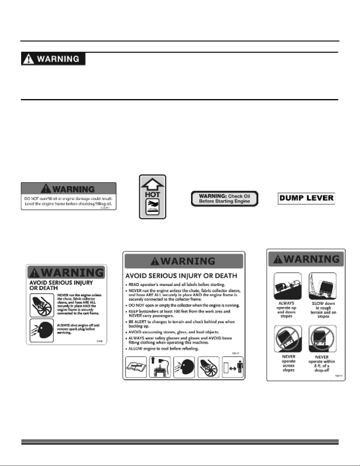
Remove objects such as stones, glass, and metal objects such as cans.
Watch out for holes, ruts, or bumps. Tall grass can hide obstacles.
NEVER:
Never vacuum near drop-offs, ditches, or embankments. Your tractor and the vacuum may tip over.
Never vacuum on slopes greater than 15 degrees or any excessively steep slopes.
Never vacuum on wet slopes. Reduced traction could result in slipping and a possible roll over.

6DR®PILOT™ LEAF and LAWN VACUUM
California Proposition 65:
Engine exhaust and some of its constituents are known to the State of California to cause cancer, birth defects, and other
reproductive harm.
This product contains or emits chemicals known to the State of California to cause cancer, birth defects, and other
reproductive harm.
General Safety (continued)
California Proposition 65
The DR Leaf and Lawn Vacuum must be operated safely to prevent or minimize the risk of minor or moderate injury. Unsafe
operation can create a number of hazards for you. Always take the following precautions when operating this machine:
Keep in mind that the operator or user is responsible for accidents or hazards occurring to other people, their property, and
themselves.
Never use the DR Leaf and Lawn Vacuum to vacuum anything but yard waste, such as leaves, grass, small twigs and pine
cones.
If the machine starts to make an unusual noise or vibration, immediately shut off the engine, disconnect the spark plug wire,
and allow all moving parts to come to a complete stop and cool. Inspect for clogging or damage. Clean and repair and/or
replace damaged parts.
See manufacturer’s instructions for proper operation and installation of accessories. Only use accessories approved by DR
Power Equipment.
Always keep the equipment in a good safe operating condition. Always make certain nuts and bolts are tight and always use
the supplied self-locking hardware; do not substitute.
Never run the engine unless the chute, fabric collector sleeve, and hose are all securely in place and the engine frame is
securely connected to the main frame.
Check behind your DR Leaf and Lawn Vacuum before backing up. You cannot see directly behind the collector box.
Never attempt to open or empty the collector while the lawn tractor deck is engaged or the DR Leaf and Lawn Vacuum engine
is running. Debris may exit at high velocity as you begin to open the collector.
Do not operate in sandy areas where you will vacuum large quantities of sand. Sand will erode the vacuum housing. Check
for holes after each use and replace the housing and liner when holes develop.
Never operate the machine on slopes greater than 15 degrees.
Never tow the DR Leaf and Lawn Vacuum faster than 8 mph.
Always shut off the lawn tractor engine and the DR Leaf and Lawn Vacuum engine and disconnect the spark plug wire before
attempting to clear any obstructions from the hose.
Use the DR Leaf and Lawn Vacuum only in daylight.
Never straddle or reach over the engine area at any time.
Use only your hands to operate the DR Leaf and Lawn Vacuum engine controls.
Do not, under any conditions, remove, bend, cut, fit, weld, or otherwise alter standard parts on the DR Leaf and Lawn
Vacuum. Modifications to your machine could cause personal injuries and will void your warranty.
Do not alter or tamper with safety devices or shields. Make sure they are in their proper position.
While using the DR Leaf and Lawn Vacuum, do not hurry or take things for granted.
Never leave the DR Leaf and Lawn Vacuum unattended with its engine running.
Do not operate the machine when under the influence of alcohol, drugs, or medication.

CONTACT US AT w w w .DRpow er.com 7
A Note to All Users
Under California law, and the laws of some other states, you are not permitted to operate an internal combustion engine using
hydrocarbon fuels without an engine spark arrester. This also applies to operation on US Forest Lands. All DR®PILOT™ LEAF
and LAWN VACUUMS shipped to California, New Mexico and Washington State are provided with spark arresters. Failure of the
owner or operator to maintain this equipment in compliance with state regulations is a misdemeanor under California law and
may be in violation of other state and/or federal regulations. Contact your State Park Association or the appropriate state
organization for specific information in your area.
No list of warnings and cautions can be all-inclusive. If situations occur that are not covered by this manual, the operator must
apply common sense and operate this DR®PILOT™ LEAF and LAWN VACUUM in a safe manner. Contact us at
www.DRpower.com or call 1-800-DR-OWNER (376-9637) for assistance.

8DR®PILOT™ LEAF and LAWN VACUUM
Chapter 2: Setting Up the DR PILOT™ LEAF and LAWN VACUUM
It may be helpful to familiarize yourself with the controls and features of your DR PILOT™ LEAF and LAWN VACUUM as shown in
Figure 1 before beginning these procedures. If you have any questions at all, please feel free to contact us at
www.DRpower.com.
DR PILOT™ LEAF and LAWN VACUUM Controls and Features
Collector Sleeve
Hose Support
Dump
Leve
r
Collector
Outlet
Chute
Collector
Base
Power Unit
Wheels
Figure 1
Pneumatic
Tires
Tow Hitch
Choke
A
ir Filte
r
Gas Shut-Off
Starter Recoil Handle
On/Of
f
Switch
Gas Fill
Inlet Hose with Cuff
Muffler
Throttle

CONTACT US AT w w w .DRpow er.com 9
Specifications
Engine DR Power Equipment R225
Ft-lbs Torque 9.59
Starting Manual
RPM 3800
Impeller Steel, 5 Blades w/Serrated Teeth
Weight 13.2 Lbs
Mount Direct Mount on Tapered Engine Shaft
Vacuum 2038 CFM
Suction 66 MPH
Hose 8" ID x .035" Wall PVC, 72" L
Collector Over-center Tilt Design w/ Flatbed Base
Volume 27 Cuft, 200 Gallons
Capacity 400 Lbs
Fabric Enclosure 1800 Denier Polyester, Solution Dyed, Bonded PVC Backing
Dump Tilt 55°
Base Flatbed, Steel
Frame Welded Steel, 2 Piece Modular Design
Impeller Housing Steel Scroll (.12" Thick), Sideplate (.12" Thick)
Wheels Pneumatic 5.30/4.50-8 4 Ply w/ Tube
Quantity 2 (1 Per Side)
Tire Size 14" Diameter x 4.5" Wide
Jack Optional Accessory
Lawn Mower 12 HP Min Flat Terrain otherwise 14 HP
Lawn Mower Hitch Pin Hitch 8" to 15" from the Ground
Dimensions 87.8" L x 40.1" W x 52.6" H
Weight 230 Lbs
Assembly Parts Identification
Compare the contents of the Shipping Box with the Parts Supplied lists and
Figures 2 thru 6 below. If there are any questions contact us at
www.DRpower.com or call 1-800-DR-OWNER (376-9637).
Tools and Supplies Needed:
Two 9/16" Wrenches
Needle Nose Pliers
Two 1/2" Wrenches
Two 3/4" Wrenches
Parts supplied in Shipping Box (Figure 2):
Item # Part # Description Qty
1 .............38858 ..............Chute, Impeller Outlet ................................... 1
2 .............33797 ..............Clamp, Hose, 8", Thumbscrew...................... 1
3 .............34248 ..............Cuff, Hose, 8"................................................. 1
4 .............33796 ..............Clamp, Hose, 8", LH Bridge .......................... 2
5 .............33795 ..............Hose, 8"ID x 72" Long, PVC .......................... 1
6 .............38854 ..............Enclosure, Fabric............................................ 1
7 .............38844 ..............Tube, Collector ............................................... 2
8 .............34244 ..............Rod, Support Hose......................................... 1
9 .............38866 ..............Batten, FRP, .58" X .12" X 29.4"..................... 4
10 ...........33801 ..............Axle ................................................................. 1
11 ...........38852 ..............Tube Frame, Top Rear.................................... 1
12 ...........38851 ..............Tube Frame, Top Front .................................. 1
13 ...........33794 ..............Wheel & Tire, 14X 5.3/4.50-8, 4 Ply ............... 2
Power Unit
1
13
12
11
9
Rear Frame
and Collecto
r
Base Assembl
y
7
6
4
10
5
Parts Box
Figure 2
3
2
8

10 DR®PILOT™ LEAF and LAWN VACUUM
1
Figure 5
2
Parts Box (Figure 3):
Item # Part # Description Qty
1 ............. 33802 .............. Axle Bracket .................................................... 2
2 .............38845 .............. Bracket, Tube, Front, LH................................ 1
38846 .............. Bracket, Tube, Front, RH ............................... 1
3 ............. 34247.............. Strap, Rubber ................................................. 1
35042 .............. Hook, Strap .................................................... 2
4 ............. 38860 .............. Knob Set ......................................................... 1
5 ............. 35021.............. Hardware Set, Wheels.................................... 1
6 ............. 38867 .............. Hardware Set, Power Unit ............................. 1
7 ............. 37036 .............. Funnel, Oil Flexible (snap together).............. 1
8 ............. 38847 .............. Bracket, Tube, Rear, LH ................................. 1
38848 .............. Bracket, Tube, Rear, RH................................. 1
Hardware in Product Package (Figure 4):
Item # Part # Description Qty
1............. 21154.............. Pin, Clevis, 1/2" X 3.5"L, ZP...........................2
2............. 35037.............. Bolt, Hex, 7/16-20, Impeller Tool...................1
3............. 18737.............. Pin, Clevis, 1/2 x 4.5"L, ZP .............................1
4............. 18967.............. Washer, Rubber, 1/2" ID, 1" OD....................1
5............. 35027.............. Bolt, C-Head, 5/16-18 X 1.75", ZP .................4
6............. 11076.............. Nut, Nylon Lock, 5/16-18 ...............................8
7............. 13443.............. Bolt, HCS, 5/16-18 X 1.5", GR5, ZP ...............8
8............. 16003.............. Clip, Pin Hitch, 1/2"-9/16" .............................3
Knob Set (Figure 5):
Item # Part # Description Qty
1............. 38861.............. Knob, 3 Prong, 5/16-18 Stud..........................6
2............. 35030.............. Knob, 5/16-18 W/Lock, 1.16 DIA. ..................4
Figure 4
1
2
4
8
3
7
6
5
Figure 3
1
8
Product
Package
7
5
2
3
4
6

CONTACT US AT w w w .DRpow er.com 11
1 2
4
3
Figure 7
5
1 2
4
3
Figure 6
Wheels Hardware Set (Figure 6):
Item # Part # Description Qty
1 .............35039 ..............Washer, 1.06" ID X 2" OD X .13", ZP ............ 4*
2 .............12334 ..............Bolt, HCS, 3/8-16 X 1.75", GR5, ZP...............4
3 .............33333 ..............Nut, Nylon Lock, Flange, 3/8-16....................4
4 .............12685 ..............Pin, Cotter, 3/16" X 1.5"................................. 2
* Only two of the 1.06" ID X 2" OD X .13" Washers will be used for this
machine.
Power Unit Hardware Set (Figure 7):
Item # Part # Description Qty
1 .............26556 ..............Bolt, HCS, 1/2-13 X 2.75", GR5, ZP............... 2
2 .............35023 ..............Bolt, Hex, Flange, 5/16-18 X .75"................... 4
3 .............11243 ..............Washer, Lock, 5/16", Split, ZP....................... 4
4 .............11241 ..............Washer, Flat, 5/16" USS, ZP.......................... 4
5 .............33335 ..............Nut, Nylon Lock, Flange, 1/2-13.................... 2
Installing the Wheels
(Use Wheel Hardware Set, see Figure 6)
Tools Needed:
Two 9/16" Wrenches
Pliers
1. Position the Rear Frame and Collector Base Assembly upside down (Figure
8).
2. Install the Axle Brackets and loosely secure with the Bolts and Locknuts
using two 9/16" Wrenches.
3. Slide the Axle through the Brackets until the same amount sticks out on
each side (Figure 9). Do not tighten the hardware until you are finished step
7 on the following page.
4. Slide a Wheel onto the Axle with the Valve Stem facing out and install a
1.06" ID X 2" OD X .13" Washer against the Wheel (Figure 10).
Note: There are four 1.06" ID X 2" OD X .13" Washers in the wheels hardware set.
Only two will be used for this machine.
Rear Frame
Figure 8
Collector
Base
A
xle
Bracket
Bolts and
Locknuts
Washer
Figure 10
Wheel
A
ir Valve
Figure 9
A
xle
Brackets
A
xle

12 DR®PILOT™ LEAF and LAWN VACUUM
Outlet Chute
Figure 12
Impeller
Housing
Bolts, Lock Washers ,
and Flat Washers
5. Secure the Wheel onto the Axle with a Cotter Pin. Use Pliers to bend the
ends of the Cotter Pin to secure the Wheel (Figure 11).
6. Repeat for the Wheel on the opposite side.
7. Tighten the Axle Bracket Hardware you installed in step 2.
8. Tip the Frame and Base over onto the Wheels.
Assembling and Installing the Power Unit
(Use Power Unit Hardware Package, see Figure 7)
Tools Needed:
1/2" Wrench
Two 3/4" Wrenches
Flat Head Screwdriver or 9/32" Wrench
1. Place the Outlet Chute on top of the Impeller Housing (make sure to orient
it as shown) and secure with four Bolts, Lock Washers, and Flat Washers
using a 1/2" Wrench (Figure 12).
2. Position the Power Unit at the front of the Rear Frame with the Tow Hitch
facing forward (Figure 13).
Note: Clevis Pins and Hitch Clips needed for the next steps are provided in the
Product Package.
3. Lift the Rear Frame and Power Unit to align the two sets of side holes and
insert a 1/2" X 3.5" Clevis Pin into each (Figure 14).
4. Secure each Clevis Pin with a Hitch Clip.
5. Place the two 1/2-13 X 2.75" Bolts from underneath up through the two
vertical Holes and secure with 1/2-13 Locknuts using two 3/4" Wrenches
(Figure 15).
1/2-13 Bolts
and Locknuts
Figure 15
Clevis Pins and
Hitch Clips
Figure 14
Figure 13
Rear
Frame
Side
Hole
s
Tow
Hitch
Side
Hole
s
Figure 11
Washer
Cotter Pin
We recommend having a helper to attach the Frames together. There is a
chance for injury if you attempt alone because the Power Unit is heavy.

CONTACT US AT w w w .DRpow er.com 13
Installing the Inlet Hose
Note: One end of the Inlet Hose has a Cuff that will later attach to your Tractor
Deck Adapter. First you will attach the other without a Cuff to your PILOT™
LEAF and LAWN VACUUM Power Unit.
1. Using a Flat Head Screwdrive or 9/32" Wrench, loosen the Hose Bridge
Clamp on the end of the Hose, slide the Hose onto the Housing neck, and
tighten the Hose Bridge Clamp very tightly (Figure 16).
2. Slide the Hose Support into the Bracket holes (Figure 17).
Note: Make sure the Hose Bridge Clamp is past the Retaining Bumps on the
Housing.
3. Support the Hose with the Rubber Strap by hooking one end into the
Support Loop, going under the Hose and securing the other end onto the
Support Loop (Figure 18).
Assembling the Collector
(Use Bolts and Locknuts from Product Package, see Figure 4)
(Use Knob Set, see Figure 5)
Tools Needed:
Two 1/2" Wrenches
1. Unfold the fabric Enclosure and place it onto the Collector base (Figure 19).
Position the Enclosure with the DR logo facing up and the Enclosure Sleeve
positioned at the front right hand corner.
Figure 19
Enclosure
Sleeve
Fabric
Enclosure
Collector Base
DR Logo
Hose
Figure 18
Rubber Strap
Hose Support
Inlet Hose
Figure 16
Bridge Over
Hose Rib
Hose Bridge
Clamp
Retaining
Bump
Clamp
A
rea
Hose Support
Figure 17
Hose
Support
Bracket

14 DR®PILOT™ LEAF and LAWN VACUUM
2. Standing on the right side of the machine, insert the ends of the first
Collector Tube into the corner loops in the Enclosure (Figure 20). Note the
orientation of the DR Logo and top Velcro Flaps.
3. Push the Tubes through until the they stick out the other end approximately
5-1/2" (Figure 21).
4. Flip the Enclosure over (Figure 22) so the other side is facing up (Figure 23).
5. Go to the left hand side of the machine (Figure 24).
6. Insert the ends of the second Collector Tube into the corner loops in
Enclosure.
DR Logo
Collector
Tube
Figure 24
Left Side o
f
Machine
Loop Opening
at Enclosure
Corner
s
Velcro
Flaps
Figure 23
Figure 22
Collector
Tube
Figure 21
A
pproximately
5-1/2"
Collector
Tube
Figure 20
DR Logo
Right Side
o
f
Machine
Loop Opening
at Enclosure
Corner
s
Velcro
Flaps

CONTACT US AT w w w .DRpow er.com 15
7. Push the Tubes through until the they stick out the other end approximately
5-1/2" (Figure 25).
8. Go to the right hand front corner of the machine (Figure 26). Confirm that
the Sleeve of the Fabric Enclosure is oriented as shown and the DR Logo is
oriented as shown.
Note: The right and left hand Front Tube Brackets must be mounted correctly at
the end of the Collector Tubes. Pay close attention to the orientation in the
Figures to verify that you have the correct Bracket.
9. Position the right hand (RH) Front Tube Bracket on the top Tube as shown
and secure with two Bolts and Locknuts using two 1/2" Wrenches (Figure
27). Do not fully tighten. Ensure the fabric doesn’t get pinched under the
Bracket.
10. Position the left hand (LH) Front Tube Bracket on the bottom Tube as
shown and secure with two Bolts and Locknuts using two 1/2" Wrenches
(Figure 28). Do not fully tighten. Ensure the fabric doesn’t get pinched
under the Bracket.
LH Front
Tube Bracke
t
Figure 28
Bolts and
Locknut
s
RH Front
Tube Bracke
t
Figure 27
Bolts and
Locknut
s
Figure 26
Right Hand
Front Corne
r
Collector
Tube
Figure 25
A
pproximately
5-1/2"

16 DR®PILOT™ LEAF and LAWN VACUUM
Note: The right and left hand Rear Tube Brackets must be mounted correctly at the
end of the Collector Tubes. Pay close attention to the orientation in the Figures to
verify that you have the correct Bracket.
11. At the rear of the Enclosure, position the right hand (RH) Rear Tube Bracket
on the top Tube as shown and secure with two Bolts and Locknuts using
two 1/2" Wrenches (Figure 29). Do not fully tighten. Ensure fabric doesn’t
get pinched under the Bracket.
12. Position the left hand (LH) Rear Tube Bracket on the bottom Tube as shown
and secure with two Bolts and Locknuts using two 1/2" Wrenches (Figure
30). Do not fully tighten. Ensure fabric doesn’t get pinched under the
Bracket.
13. Lift the Enclosure and insert the ends of the Collector Tubes into the holes
at the corners of the Collector Base (Figure 31).
14. Secure the rear Tube Brackets to the Collector Base with one Hand Knob
with Stud for each Bracket (Figure 32). Do not tighten fully.
15. Secure the front Tube Brackets to the Collector Base with two Hand Knobs
with Studs for each Bracket (Figure 33). Do not tighten fully.
Hand Knob
with Stud
Figure 33
Front Tube
Bracket
Collector
Base
Hand Knob
with Stud
Figure 32
Rear Tube
Bracket
Collector
Base
Holes in Corners
of Base
Figure 31
Collector
Tube
s
LH Rear
Tube Bracke
t
Figure 30
Bolts and
Locknut
s
RH Rear
Tube Bracket
Figure 29
Bolts and
Locknut
s

CONTACT US AT w w w .DRpow er.com 17
16. Install the top front Tube Frame to the side Tube Frames and secure with
two C-Head Bolts and Knobs (Figure 34).
17. Slide the Top Rear Tube Frame through the Enclosure Loop and secure to
the Side Tube Frames with two C-Head Bolts and Hand Knobs with threads
(Figure 35).
Note: The round Tube portion of the Top Rear Tube Frame is offset from the flat
ends. Install so the offset is facing out towards the back.
18. Adjust the enclosure corner loops so that there is about 1/2" of tube
showing above the tube brackets (Figure 36).
19. Open up the side Loops by pulling at the Velcro closures to separate them
(Figure 37).
20. Fold the Inner Flap over the side Tube Frame and secure the Velcro next to
the Outer Flap (Figure 38). Repeat for the other side.
Top Rear
Tube Frame
Figure 35
Top
Rear
Loop
Hand
Knob
with
Threads
C-Head
Bolt
Tube
Frame
End
Tube Offset
Facing out
Outer
Flap
Figure 38
Inner Flap
Velcro
Side Loop
with Velcro
Figure 37
A
pproximately
1/2"
Figure 36
Top Front
Tube Frame
Figure 34
Hand
Knob
with
Threads
C-Head
Bolts
Bracket

18 DR®PILOT™ LEAF and LAWN VACUUM
21. Lift the Outer Flap up and secure it to the Velcro on the Inner Flap. Repeat
for the other side (Figure 39).
22. Open up the Front Loop by pulling at the Velcro closures to separate them
(Figure 40).
23. Fold the Outer Flap over the Front Tube Frame and secure the Velcro next to
the Inner Flap (Figure 41).
24. Fold the inner Flap over the outer flap and secure the Velcro at the front
(Figure 42).
25. Slide the Enclosure Sleave over the Outlet Chute (Figure 43).
26. Tighten all hardware installed in steps 9 thru 17.
27. Separate the left and right side Doors by disconnecting the three Buckles
(Figure 44).
28. Separate the top and bottom Doors by disconnecting the three Buckles
(Figure 45).
Enclosure
Sleeve
Figure 43
Outlet
Chute
Buckle
s
Figure 45
Top
Bottom
Buckles
Figure 44
Left
Side
Right
Side
Figure 42
Inner
Flap
Velcro
Outer Flap
Figure 41
Inner
Flap
Velcro
1
2
Front Loop
with Velcro
Figure 40
Outer
Flap
Figure 39
Velcro

CONTACT US AT w w w .DRpow er.com 19
Note: There are seams sewn along the edges of the Door Panels to create Pockets
that the Battens must be inserted into (Figure 46). This will enhance the
performance of the latching system. One end of the Batten Pocket is open
with an elastic flap concealing the opening. The other end is sewn together to
retain the Batten.
29. Insert the Batten under the Elastic Flap at the corner and push it in a bit
until it hits the seam (Figure 47).
30. Flip the Batten over 180 degrees and push it into the large pocket that runs
the length of the edge and insert it in until it stops at the other end (Figure
48).
31. Pull the Elastic Flap out and over the end of the Batten to secure it. Repeat
for the other three Battens (Figure 49).
32. Secure the top Door to the bottom Door with the three Buckles (Figure 50).
33. Secure the side Doors together with the three Buckles (Figure 51).
Buckles
Figure 51
Left
Side
Right
Side
Buckle
s
Figure 50
Top
Bottom
Secured, No
Batten Showing
Figure 49
Large
Pocket
Figure 48
Batten
Figure 47
Elastic
Flap
Figure 46
Batten
Locations

20 DR®PILOT™ LEAF and LAWN VACUUM
Setting up your Lawn Mower
Hitch Plate Kit Installation (optional)
The DR PILOT™ LEAF and LAWN VACUUM requires a Pin Hitch hole on your
Lawn Mower. DR Power Equipment offers several different Hitch Plate Kits if
one is not provided on your Mower (Figure 52). Contact us at
www.DRpower.com or call one of our representatives at 1-800-DR-OWNER (376-
9637) and they will be happy to assist you.
Deck Adapter Installation
The DR PILOT™ LEAF and LAWN VACUUM requires a Deck Adapter on your
Lawn Mower to route material to its 8" diameter hose.
A DR Power Equipment Universal Deck Adapter Kit (for right hand
discharge mowers) is available for you to fit to your machine if the
Mower manufacturer’s Deck Adapter is not available.
A DR Power Equipment Hose Adapter Kit is available to attach to your
non DR Power Equipment Deck Adapter to our 8" diameter Hose if
needed.
Contact us at www.DRpower.com or call one of our representatives at 1-800-DR-
OWNER (376-9637) to order a Universal Deck Adapter Kit or Hose Adapter Kit.
1. Install the Deck Adapter onto your Lawn Mower (Figure 53).
2. If you do not have a DR Deck Adapter and the 8" Hose will not fit your
Adapter, order a Kit from us using the contact info above. Install the Hose
Adapter Kit onto the end of your Deck Adapter as described in the Kit
instructions.
Connecting the DR PILOT™ LEAF and LAWN VACUUM to your
Mower
1. Position the back Hitch Plate of your Mower near the Hitch of the PILOT™
LEAF and LAWN VACUUM on level ground (Figure 54).
2. For models not equipped with a Jack, lift the Leaf System Tow Hitch onto the
Hitch Plate as shown. For models equipped with a Jack, operate the Jack to
move the Frame up or down until the Tow Hitch is aligned with the Mower
Hitch Plate.
3. Move the Leaf System into position on the Hitch Plate and install the Hitch
Pin with Rubber Washer and Hitch Clip to secure the Tow Hitch to the
Mower.
4. For models with a Jack, raise the Jack Wheel and install the Jack Safety Pin.
Figure 54
Hitch Pin
Hitch Clip
Tow Hitch
Rubber
Washer
Hitch
Plate
Figure 52
Optional Hitch Plate Configurations
Deck
A
dapte
r
Figure 53
Always raise the Jack (if equipped) prior to towing this equipment. An
extended Jack can damage or deform the Jack or Frame if the Jack hits the
ground or an obstacle.
Table of contents
Other DR Lawn And Garden Equipment manuals

DR
DR Stump Grinder User manual

DR
DR DR Quick start guide

DR
DR 48" LANDSCAPE RAKE Quick start guide

DR
DR PRO MAX450 Quick start guide

DR
DR Premier Quick start guide

DR
DR Premier Quick start guide

DR
DR DR TRIMMER/MOWERTM BEAVER BLADE Quick start guide

DR
DR DR LEAF LAWN Quick start guide

DR
DR Manual-Start - Push Quick start guide

DR
DR Premier Quick start guide
Popular Lawn And Garden Equipment manuals by other brands

Black & Decker
Black & Decker GS500 instruction manual

Lifetime
Lifetime #60078 Assembly instructions

Gardena
Gardena AccuCut Li Operation instructions

barebones
barebones raised grow bed user guide

Mantis
Mantis 2224 DAHM Owner's manual and assembly instructions

juwel
juwel PROFILINE 20590 Assembly instructions