Dragon Wholesaling LF750 User manual

Manual
V 1.7
LF750 LIFTER
USER MANUAL
Applicable to LF750 (Mk1):
MC No. 001

Manual
V 1.7 Page 1of 47
Contents
Introduction ............................................................................................................................................4
Limitations...........................................................................................................................................4
Delivery................................................................................................................................................4
Important Health and Safety Information ............................................................................................4
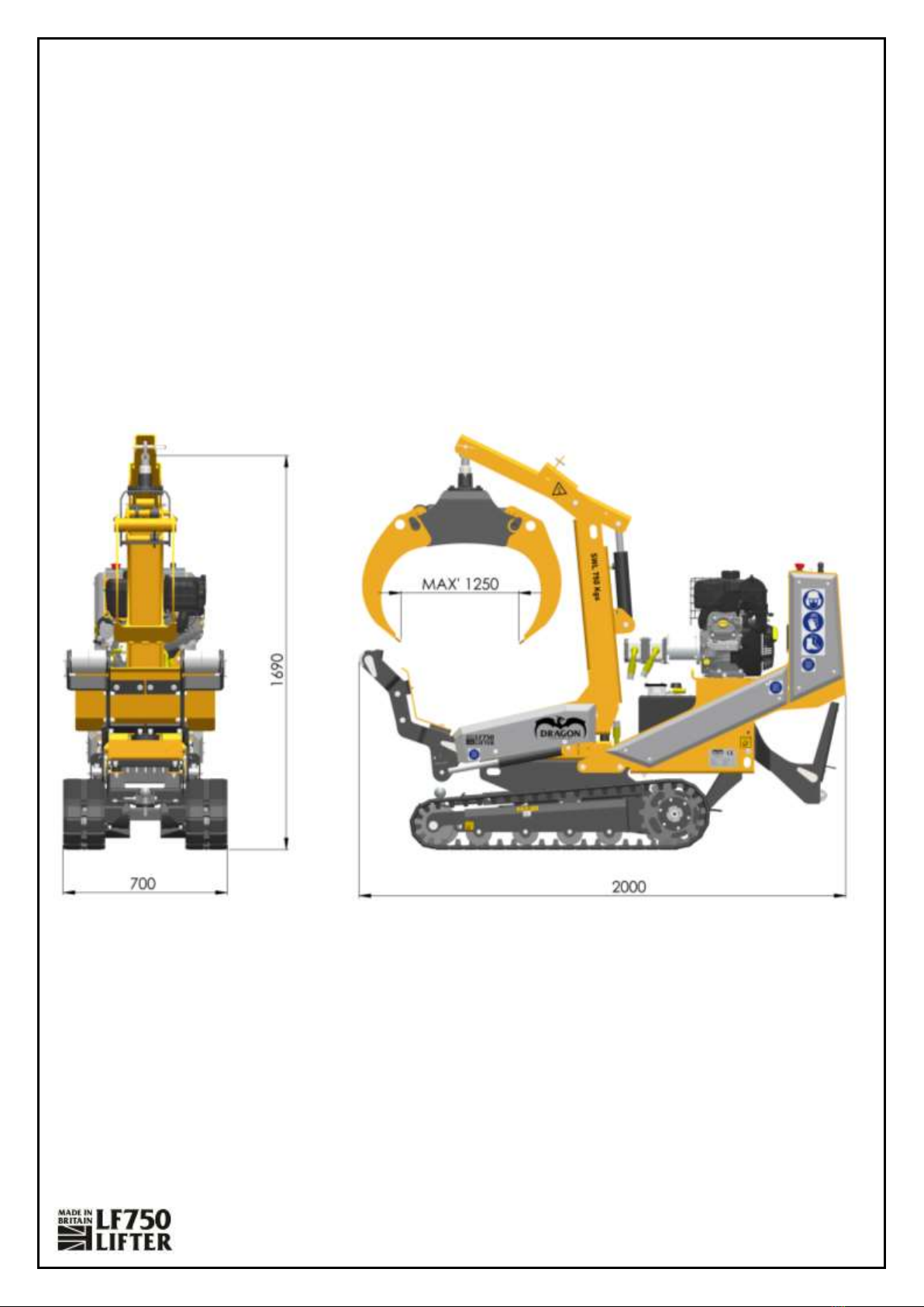
Specifications ..........................................................................................................................................5
Safe Working...........................................................................................................................................7
Operator’s Personal Protective Equipment (PPE).................................................................................7
Basic Operation Safety.........................................................................................................................7
General Safety Matters........................................................................................................................7
Engine Noise........................................................................................................................................8
Refuelling.............................................................................................................................................8
Operating Instructions............................................................................................................................9
Storage and Parking.............................................................................................................................9
Starting the Machine .........................................................................................................................10
Checks Before Starting..................................................................................................................10
Starting Procedure........................................................................................................................10
Stopping the Machine........................................................................................................................11
Emergency Stopping ..........................................................................................................................11
Tracking the Machine.........................................................................................................................12
Tracking Controls ..........................................................................................................................12
Checks Before Tracking.................................................................................................................12
Tracking Procedure .......................................................................................................................12
Lifting and Auxiliary Accessory ...........................................................................................................14
Lifting and Auxiliary Controls........................................................................................................14
General Lifting Operation .............................................................................................................14
Connecting and Disconnecting the Auxiliary Accessory ...............................................................15
Log Grab Accessory & Operation..................................................................................................16
Troubleshooting....................................................................................................................................17
Service Instructions...............................................................................................................................18
Safe Maintenance..............................................................................................................................18
Safe Lifting and Securing of the LF750 Lifter ................................................................................18
Lubrication and Servicing..............................................................................................................18
Recommended Lubricants ............................................................................................................18

Manual
V 1.7 Page 2of 47
Spares................................................................................................................................................18
Service Schedule................................................................................................................................19
Engine Servicing ............................................................................................................................19
Hydraulic Hose Check....................................................................................................................19
Changing Hydraulic Oil Filter.........................................................................................................20
Changing Hydraulic Oil and Filter..................................................................................................20
Grease Moving Parts.....................................................................................................................21
Grease Track Tensioners...............................................................................................................21
Check Fittings.....................................................................................................................................22
Hazardous Materials and End of Machine Life ...................................................................................22
Battery Safety Information.................................................................................................................23
Safety Advice:................................................................................................................................23
Fire and Explosion Data: ...............................................................................................................23
Storage and Handling / Use: .........................................................................................................23
Warranty Statement .............................................................................................................................24
Declaration of Conformity ....................................................................................................................26
Identification Plate................................................................................................................................27
Decals....................................................................................................................................................28
Electrical Circuit Schematic...................................................................................................................30
Electrical Component Parts List..........................................................................................................31
Hydraulic Circuit Schematic ..................................................................................................................32
Hydraulic Hose and Component Parts List..........................................................................................33
NOTE: Individual replacement hoses are available. Part Diagrams.....................................................33

Manual
V 1.7 Page 3of 47
List of Figures:
Figure 1: LF750 Lifter Dimensions...........................................................................................................5
Figure 2: Summary of Switches, Controls and Gauges ...........................................................................9
Figure 3: Engine Parts and Controls......................................................................................................10
Figure 4: Tracking Controls ...................................................................................................................12
Figure 5: Tracking Angle Limits .............................................................................................................13
Figure 6: Operation When Loaded........................................................................................................13
Figure 7: LF750 Lifter and Auxiliary Controls........................................................................................14
Figure 8: Log Grab Operation................................................................................................................16
Figure 9: Changing the Hydraluiic Oil Filter ..........................................................................................20
Figure 10: Hydraulic Oil level ................................................................................................................20
Figure 11: Grease Nipples and Pins.......................................................................................................21
Figure 12: Track Tension.......................................................................................................................21
Figure 13: Identification Plate...............................................................................................................27
List of Part Diagrams:
Drawing 1: Track Tensioner Wheel & Lower Roller Assy......................................................................35
Drawing 2: Track Assy 180x60x47 RH & LH V1 .....................................................................................36
Drawing 3: Track Base 4W700W V3......................................................................................................37
Drawing 4: Hydraulic Tank Assy V1.......................................................................................................38
Drawing 5: Petrol Engine & Pump Assy V1 ...........................................................................................39
Drawing 6: Track Tower Assy V3...........................................................................................................40
Drawing 7: Platform Folding Assy V1....................................................................................................41
Drawing 8: Tracking Power Unit Briggs 4W700W.................................................................................42
Drawing 9: LF750 Head Unit (Boom & Dipper).....................................................................................43
Drawing 10: LF750 Head Unit (OutRigger)............................................................................................44
Drawing 11: LF750 Head Unit (Main)....................................................................................................45
Drawing 12: LF750 Lifter & Machine Guards........................................................................................46

Manual
V 1.7 Page 4of 47
Introduction
Thank you for choosing Dragon Equipment. Our Lifting Machinery is designed to give safe and
reliable service if operated in accordance with the instructions which are provided as a guide to
familiarise the operator with the controls, inspections, start-up, operating, and shutdown
procedures.
Limitations
The LF750 Lifter is designed to lift and transport up to 750 kg with the user operating the
machine from the platform.
A maximum unloaded tracking angle of 20°.
When loaded, only operate or tracked on level and stable ground.
Delivery
All Dragon Equipment LF750 Machines have a full pre-delivery inspection before leaving the factory
and are ready to use. Read and understand this instruction manual before attempting to operate or
move the lifter. In particular, read pages 4-8 which contain important health and safety information
and advice.
Important Health and Safety Information
Before using your new lifter, please take the time to read this manual. Failure
to do so could result in:
Personal injury.
Equipment damage.
Property damage.
Third-party injuries.
The machine must be properly operated and maintained to keep it in a safe
and efficient functioning condition. Ensure that all controls are free of mud,
grease, or other matter that might cause slips hazardous to the operator or
other personnel. Report all malfunctions to those responsible for maintenance
or site safety. Do not operate the equipment until corrected. Normal service
or maintenance performed as required can prevent unexpected and
unnecessary downtime. This handbook describes general inspections,
servicing and operation with the normal safety precautions required for
normal operation.
This manual covers the operation and maintenance of the Dragon Equipment LF750. All information
in this manual on how to operate the machine safely is based on the latest product information
available at the time of purchase. All operators must be properly trained in safe working practices
before operating this machine.
Dragon Equipment’s policy of continuous improvement on the design of their products may result in
modifications to the lifter or their accessories. Dragon Equipment reserves the right to make
modifications at any time without notice and obligation. This may result in minor discrepancies
between this manual and the purchased product.

Manual
V 1.7 Page 5of 47
Specifications
Width: 700mm
Length: 2,000mm
Height: 1960mm
Weight: 630 Kg
SWL: 750 Kg
Log Grab: 1250mm max opening
Engine Power: 10kW (14 HP)
Start: Electric and Recoil
Fuel: Petrol
Figure 1: LF750 Lifter Dimensions

Manual
V 1.7 Page 6of 47
Parts Locator
Figure 2: Parts Locator
The LF750 has the following fixed guards for the protection of the operator and environment:
Hydraulic Guard: Protects hydraulic cylinders from damage during operation.
Control Tower Guard: Protects valves from the environment.
Hose Guards: Prevents damage to hoses.
These guards may be removed for maintenance only, however, the operator must ensure guards are
in place before operation.
Track Tension Adjustment
ID Plate
Hydraulic
Oil Tank
Battery
Engine
Machine Controls
Exhaust
Outrigger
Optional
Accessory
Boom
Dipper
Stability Foot
Fuel Tank
Hydraluic Oil Tank
Platform
Track
Guard
Cargo Bay

Manual
V 1.7 Page 7of 47
Safe Working
Operator’s Personal Protective Equipment (PPE)
Suitable work gloves.
Steel toe cap safety boots complying with ISO 20345:2011.
Appropriate close-fitting clothing.
Never wear loose clothing, rings, and watches etc. that might catch the controls.
High-visibility clothing complying with ISO 20471:2013 if required.
Eye, Head and Eye Protection if required.
Basic Operation Safety
The operator should be aware of the following points:
Ensure lifter tilt angles are within limits when transporting material on uneven ground.
Never leave the lifter unattended when in operation or with the engine running.
If an accident occurs, stop the machine, remove the key and call the emergency
services immediately.
General Safety Matters
Always ensure the engine has stopped and cooled down before making any adjustments,
undertaking maintenance, refuelling or cleaning.
Always ensure there is no risk of the machine moving during operation. Be aware of slope
inclines and surface conditions.
If there are any fluid leaks, cease operating the machine, stop the engine and repair
before continuing.
Take regular breaks, do not operate the machine when tired.
Ensure protective guards are in place before operating machine. Failure to do so may result
in personal injury or loss of life.
Always operate the lifter in a well-ventilated area to prevent the build-up of
exhaust fumes.
Ensure a fire extinguisher is available on site.
Ensure a personal first aid kit is available and know its location.
Do not operate the lifter in low light levels and be aware of changeable weather.
Do not smoke when refuelling.
Do not allow individuals to operate the machine who have not been trained.
Do not climb onto the machine.
Do not touch exposed wiring due to the risk of electric shock.
Do not use the lifter inside buildings without sufficient ventilation.

Manual
V 1.7 Page 8of 47
Engine Noise
Noise levels above 80dB (A) will be experienced at the working position. Prolonged exposure to loud
noise may cause permanent hearing loss. All persons within close vicinity of the lifter must also wear
ear protection (EN 352) at all times to prevent possible hearing damage.
The average sound pressure level at one metre for the Vanguard 400 is:
3600FL
[dBA]
3600NL
[dBA]
3000FL
[dBA]
3000NL
[dBA]
96.8
93.8
94.4
90.4
While operating the lifter ensure that all individuals comply with the Control of Noise at Work
Regulations 2005 (Noise Regulations 2005) to prevent or reduce risks to health and safety from
exposure to noise at work.
Refuelling
Follow standard Health and Safety practices.
Stop the engine and allow to cool.
Never smoke or permit naked flames nearby.
Store fuel away from any ignition sources.
Fuel storage containers must be approved, clearly display appropriate labels and have
securely fitting caps.
Use a funnel when refuelling and ensure fuel cap is refitted securely.
Avoid skin contact with fuel. If it gets into eyes wash out with sterile water immediately and
seek medical advice as soon as possible.
Always clean up after any spillages and change clothes if appropriate.

Manual
V 1.7 Page 9of 47
Operating Instructions
Storage and Parking
When parking the machine overnight, or for an extended period, the following procedure in addition
to that given in ‘Stopping the Engine’ will help maintain it in good condition for subsequent use:
Fill the fuel tank before parking the machine overnight or for extended periods to prevent
condensation.
Always park on level ground where possible. If it must be parked on a slope, position
machine at right angles to the slope and block tracks securely.
Remove the key to a place of safety.
NOTE: Always park the machine with the auxiliary attachment in contact with the ground.
NOTE: Ensure the equipment cannot be started or used by unauthorised or
untrained personnel
To recommission after storage the following checks must be carried out:
Check all fluid levels.
Check for fluid leaks.
Check the tension of rubber tracks.
Check operation of all controls.
Check the action of the Stop Lever.
Check the action of all E-Stop buttons.
Figure 2: Summary of Switches, Controls and Gauges
E-Stop
Engine RPM /
Hour Counter
Angle Indicator
Tracking / Lifting /
Aux Lever Controls

Manual
V 1.7 Page 10 of 47
WARNING
Do not use or attempt to start the lifter
without the protective guarding in place.
Failure to do so may result in personal
injury or loss of life.
Starting the Machine
Checks Before Starting
Ensure the machine is located on firm flat ground.
Check all guards are fitted.
Carefully inspect tracks for cuts or other damage.
Visually check for fluid leaks.
Ensure there is sufficient fuel in the fuel tank.
Ensure that all track levers are in the neutral
position.
Ensure E-Stop buttons are pulled out.
Figure 3: Engine Parts and Controls
Starting Procedure
Do not place engine under full load at full speed immediately after starting. Always allow the engine
to fully circulate lubricant and warm up gradually before operating at full speed and load.
Move throttle lever in direction of (BLUE arrow) to the half-way position.
Pull choke control to the full choke position in direction of BLUE arrow.
Insert key into the ignition.
Turn the key clockwise to turn ON the machine, the engine will crank over.
Release the key as soon as the engine starts.
Push the choke control to the off position soon after starting. Normally with 1-2 seconds
Allow the engine to warm up.
NOTE: To extend the life of the starter motor, use only short starting cycles - 5 seconds max.
Cap –Fuel Tank
Fuel Tank
Dip Stick
(Oil Level)
Oil Fill
(Below Exhaust)
Machine Start
Pull Cord
(Hand Start)
Choke Lever
(Bottom)
Throttle / OFF
Lever (Top)
Air Cleaner
Exhaust Muffler
Oil Drain

Manual
V 1.7 Page 11 of 47
Stopping the Machine
Move throttle lever to the STOP position in the direction of the RED arrow. This will turn off
the fuel and stop the engine in one action.
For more detailed information refer to the Engine Owner’s Manual.
NOTE: Do not use the E-Stop to turn the engine off.
NOTE: Do not try to turn the key to the off position, use throttle lever to turn
off engine.
Emergency Stopping
Should the machine need to be stopped in an emergency, push the E-Stop button. This is located on
the Track Tower Control Panel. The engine cannot be restarted until the activated E-Stop button is
reset. Before resetting the E-Stop button inspect the machine to ensure it is safe to continue
operation.
NOTE: If the engine is not to be restarted move the throttle control to off.
Failure to move the lever may cause fuel to pump when moving the machine and fill the engine
with petrol.
This will hinder starting or damage the engine permanently.

Manual
V 1.7 Page 12 of 47
Tracking the Machine
The Machine can be tracked at the same time as using the Lifting and Auxiliary Controls.
Tracking Controls
The lifter utilises the following controls for tracking:
Left-hand track lever.
Right-hand track lever.
E-Stop.
Checks Before Tracking
Always face the direction the machine is travelling.
Make sure the area around the machine is clear of personnel and obstructions before
tracking.
Always operate straight up or down slopes. Tracking across a slope can cause sideslip and
possible rollover.
When negotiating slopes greater than 10 degrees or loading onto a trailer, track the lifter in
reverse so the operator is above the LF750 Lifter, see Figure 5.
Maximum side traverse angle on a slope is 20° when unloaded, see Figure 5.
NOTE: When loaded ensure ground is level and stable.
Tracking Procedure
To steer the machine, apply pressure to the control levers.
oApply equal forward pressure on both levers to make the machine move forward in
the desired direction at speed.
oThe machine will turn by applying more or less pressure to either lever proportional
to the lever movement.
oApply equal pressure on both levers to the reverse position will make the machine
move backwards at the desired speed.
NOTE: NEVER step off the working platform while the machine is loaded.
Figure 4: Tracking Controls

Manual
V 1.7 Page 13 of 47
Figure 5: Tracking Angle Limits
Figure 6: Operation When Loaded
Always stay uphill of the machine while tracking.
DO NOT track the machine on slopes greater than 20°.
When loaded ensure ground is level and stable.
NEVER step off the working platform while the
machine is loaded.

Manual
V 1.7 Page 14 of 47
Lifting and Auxiliary Accessory
The Machine has a Main Boom, Dipper Arm and Outrigger (front stability foot), which doubles-up as
a load stabiliser when tracking. The lifting arm can have various optional accessories fitted, such as a
Log Grab or Post Hole Borer. Auxiliary accessory hydraulic hoses are connected via the quick-release
couplers on the top of the boom. Male (fluid flow OUT) Female (fluid flow IN).
Lifting and Auxiliary Controls
1. Boom Control Lever - pushing the lever forwards tilts to boom forwards and pulling the lever
back tilts the boom backwards.
2. Dipper Control Lever - pushing the lever forwards raises the dipper arm and pulling the lever
backwards lowers the dipper arm.
3. Outrigger Control Lever - pushing the lever forwards lowers the Outrigger and pulling the
lever backwards raises the Outrigger.
4. Aux Control Lever - moving the lever forwards or backward has the opposite action. The
action will depend on the accessory fitted.
General Lifting Operation
Approach the load and fully lower the outrigger to aid stability.
Position the lifting hook or accessory over the load using the Boom and Dipper control
levers.
Securely rig the load to the lifting eye or utilise the auxiliary accessory if applicable.
Lift the load onto the Cargo Bay using the Boom and Dipper control levers.
Raise the Outrigger to secure the load.
Use additional ties to secure the load if required.
Track load as required.
Unloading is the reverse of loading.
NOTE: When loaded ensure ground is level and stable.
NOTE: NEVER step off the working platform while the machine is loaded.
Figure 7: LF750 Lifter and Auxiliary Controls

Manual
V 1.7 Page 15 of 47
Connecting and Disconnecting the Auxiliary Accessory
Ensure machine is turned OFF.
Attach the required accessory to the mounting boss using the supplied fixings.
Remove coupler dust caps.
Ensure couplers faces are clean of dirt or grime.
Connect the hydraulic hoses to the auxiliary service ports on the top of the boom.
Disconnection advice:
Operate the accessory several times to relieve any pressure in the system before removing
the quick release fittings.
NOTE: The auxiliary lever is kept in the MID POSITION when DISCONNECTED.
NOTE: ALWAYS park the machine with the auxiliary attachment in contact with the ground.

Manual
V 1.7 Page 16 of 47
Log Grab Accessory & Operation
Log grab accessory is designed for handling timber and brash only.
Maximum opening width of 1,250mm and maximum lifting weight of 750Kgs.
Pushing the lever forwards will Open the log grab and pulling the lever backwards will Close
the log grab.
1. Approach the load and fully lower the
outrigger to aid stability.
NOTE: Track backwards/forwards as required.
2. Position the log grab over the timber using the
Boom and Dipper control levers, then open the
Log grab.
3. Close the log grab jaws around the timber.
NOTE: Ensure the TIMBER IS EVENLY
DISTRIBUTED before lifting.
4. Lift the load and place onto the cargo bay.
NOTE: Ensure the timber is resting on the
cargo bay and secure.
5. Raise the outrigger and ensure the timber is
secure, use straps if required.
NOTE: DO NOT suspend timber from the
dipper when transporting.
6. Unloading is the reverse of loading.
NOTE: NEVER step off the working platform
while the machine is loaded.
NOTE: When loaded ensure ground is level
and stable.
NOTE: ALWAYS park the machine with the log
grab in contact with the ground.
Figure 8: Log Grab Operation

Manual
V 1.7 Page 17 of 47
Troubleshooting
•The machine will not track:
oItem jammed into drive sprocket –change direction and remove the item.
oEnsure hydraulic oil level is correct
•The machine will not lift:
oThrottle control is set too slow–ensure the lever is fully across.
oEnsure hydraulic oil level is correct
•The machine lifts erratically:
oThrottle control is set too slow–ensure the lever is fully across.
•The engine will not crank:
oBattery charge low –charge as required or replace.
oUse the Hand Pull to start the engine –This will also charge the battery.
oFuel lever not been turned off –remove Spark Plug to allow fuel to evaporate.
•The engine will crank, but not start:
oEnsure all E-Stops are in the off position.
oEngine too hot –turn off choke as not required.
oEngine too cold –turn on choke as required.
oNo fuel in the tank –check the level and fill as required.
oWrong fuel in the tank –drain fuel from tank and carburettor and replace with the
correct grade of petrol.

Manual
V 1.7 Page 18 of 47
Service Instructions
Safe Maintenance
While carrying out maintenance, handle the LF750 Lifter
components with care to avoid injury, it is recommended
that gloves are worn while carrying out servicing to
minimise the risk of contact with hazardous materials. The
major components of this machine are heavy and if
required, lifting equipment should be used.
Safe Lifting and Securing of the LF750 Lifter
If the LF750 Lifter cannot be driven onto its transport
vehicle, a hoist can be used. The lifting points are
designed to lift only the machine’s weight. Always inspect
the lifting bar before use and do not use if damaged.
Maximum lift weight is as indicated on the machine data plate.
The method of securing the LF750 Lifter can vary depending on the type of carrier and position of
tie-down points available on the carrier. It is recommended that correctly rated ratchet straps are
used to secure the machine via the track frame or over the tracks to the carrier lashing points. This
must be carried out by competent qualified personnel. Failure to secure the load correctly could
result in chassis and/or undercarriage damage or loss of load.
Lubrication and Servicing
Lubrication is an essential part of preventive maintenance. The instructions regarding types of
lubricants and the frequency of their application must be followed to prolong the life of the
machine. Periodic lubrication of moving parts helps prevent the possibility of mechanical failures.
Thoroughly clean all fittings, caps, plugs etc., to prevent dirt from entering the system while
servicing. Lubricants must be at operating temperatures when draining.
Do not operate any system unless oil level is within the operating range as indicated on the dipstick,
level plug or sight glass. All change and service periods are recommendations based on average
operating conditions. Lubricants showing evidence of excessive heat, oxidation or dirt should be
changed more frequently to prevent these conditions. Lubricants change and service periods must
be established based on individual job conditions.
Recommended Lubricants
Engine - Vanguard ® Synthetic 15W-50
Hydraulic - VG32 Mineral Oil
Grease - Shell Gadus S3 V100 premium multi-purpose grease
Spares
Only fit genuine Dragon Equipment LF750 Lifter spares. Failure to do so will result in the invalidation
of the warranty and may result in damage to the lifter, personal injury or even loss of life.
WARNING
Always immobilise the machine before
undertaking any maintenance work on the
lifter by removing the ignition key and
disconnecting the battery. Ensure the lifter
is stable and on level ground before
performing any maintenance.

Manual
V 1.7 Page 19 of 47
Service Schedule
First 5 Hours
Change engine oil
Check for hydraulic oil leaks
Refer to engine manual
Page 19
Every 8 Hours or Daily
Check engine oil level
Clean Area around muffler and engine controls
Clean air intake grille
Check hydraulic oil leaks
Visually check the machine for damage
Refer to engine manual
Page 19
Every Month
Grease all lubrication points and check track tension
Page Error! Bookmark
not defined.
First 50 hours
Change hydraulic oil filter
Page 20
Every 100 Hours or Annually
Service exhaust system
Refer to engine manual
Every 200 Hours or Annually
Change engine oil
Clean air filter1
Refer to engine manual
Every 600 Hours or Every 3 years
Replace air filter
Refer to engine manual
Annually
Replace spark plug
Service fuel system
Service cooling system1
Check valve clearance2
Change hydraulic oil and replace hydraulic oil filter
Check fittings
Refer to engine manual
Page 20
Page 22
1In Dusty conditions or when airborne debris is present, clean more often.
2Not required unless engine performance problems are noted.
Engine Servicing
All engine servicing must be performed in accordance with the Engine Manufacturer’s Handbook
provided with the machine.
NOTE: Failure to adhere to this may invalidate the warranty and/or shorten engine life.
Hydraulic Hose Check
All the hydraulic hoses should be regularly inspected for chafing and leaks. The hydraulic system is
pressurized to 150 Bar (2175 PSI) and the hoses must be kept in good condition. If any hydraulic
This manual suits for next models
1
Table of contents
Popular Lifting System manuals by other brands

Rotary
Rotary 200 Series Operation and maintenance manual

Haulotte Group
Haulotte Group HA120PX Maintenance book

Dhollandia
Dhollandia DH-V Series Operation manual

Genie
Genie S-40 TRAX Service manual

Challenger Lifts
Challenger Lifts 15000-SPRINTER 15000-3S Installation, operation & maintenance manual

Ronin
Ronin Lift instruction manual

Braun
Braun NUVL855RM24 Operator's manual

CMC
CMC S28 Use and maintenance manual

Ravaglioli
Ravaglioli KPS234HE Original instructions

Nexion
Nexion Molnar CM245-A Installation, operation & maintenance instructions

Easy Lift Equipment
Easy Lift Equipment EAGLE-GRIP EL4 Series operating instructions

CMC
CMC S19 Use and maintenance manual