Dragon Wholesaling SY-252N User manual

R
DRAGON
User Manual
SY-252N
2-m VHF Amateur Transceiver

Contents:
Regulatory notes, Declaration of Conformity.....................................................................................3
Installation and Setup........................................................................................................................ 4
General remarks for operating this radio............................................................................................4
Installation as mobile radio................................................................................................................. 4
Connecting to DC po er....................................................................................................................5
Rear side connections....................................................................................................................... 5
Antenna selection.............................................................................................................................. 5
Mobile (car) antenna.......................................................................................................................... 5
SY-252N as Base Station.................................................................................................................. 6
Operation........................................................................................................................................... 6
Front panel - and microphone knobs and - keys................................................................................6
Direct entry key functions (basic functions).......................................................................................7
On / Off, Volume and Squelch settings..............................................................................................7
The LC Display of SY-252N............................................................................................................... 7
Push-to-talk button (PTT)..................................................................................................................8
TONE CALL 1750 Hz........................................................................................................................ 8
Direct access to „Call“ channel.......................................................................................................... 8
Frequency search mode SCAN......................................................................................................... 8
Recalling memory-channels MR / MS................................................................................................8
Microphone lock................................................................................................................................. 8
Second level of functions (t o-touch-functions).................................................................................9
MHz-key............................................................................................................................................. 9
Activate repeater shift (offset)........................................................................................................... 9
Activate Tone Squelch (CTCSS)....................................................................................................... 9
Prioriy channel „Dual Watch“.......................................................................................................... 10
Monitor key...................................................................................................................................... 10
Complete key locking ............................................................................................................... 10
Transmit po er s itching Hi / Lo ..................................................................................................10
The Setup Menu.............................................................................................................................. 11
Flo -chart for the Setup Menu......................................................................................................... 11
More about the menu steps............................................................................................................. 11
Terminating the setup menu............................................................................................................ 13
Reset to factory default settings and erasing all memories..............................................................14
Technical informations..................................................................................................................... 14
Saving and backup of user settings.................................................................................................14
Connecting points for accessory items............................................................................................14
Microphone iring........................................................................................................................ 14
Ext. Speaker socket......................................................................................................................... 14
Note to packet radio modem connection..........................................................................................14
Programming different options (for service only after opening the cabinet).....................................15
Technical data SY-252N.................................................................................................................. 16
2

Regulator notes, Declaration of Conformit
SY-252N
Manufacturer’s Declaration of Conformit
This amateur radio transceiver corresponds to the essential requirements of the EU Directive(s) 89/336/
EEC (EMC), Lo -Voltage-Directive 73/23/EEC, R&TTE Direktive 1999/5/EC, fulfills the harmonised
European technical standards for commercially available amateur radios EN 301 783-2, EN 301 489-1,
EN 301 489-15 and EN 60 950 and is marked ith CE and „Alert Sign“.
The radio ma be used under following regulator conditions and requirements:
In most European and overseas countries onl licenced amateur radio operators are allowed to
use this radio (e.g. in German § 1 „Gesetz über den Amateurfunk“, BGBL, Part III, Nr. 9022-1).
Even licenced radio operators are onl allowed to use the radio on frequencies, which are
allocated to the amateur radio service of their licence class. In some countries restrictions are
in force, where the ph sicall switchable frequenc range must not exceed the allocated
frequenc range limits. In such countries operators must set the programming jumpers
correctl before connecting and using the radio. Exposure of persons to radiated emissions is
also limited in some countries. Please respect the power limits and safet distances, if
requested b the local radio authorit . This radio ma be used onl for amateur radio purposes.
Use for commercial radio purposes is subject to special licences and approvals in certain
countries.
The radio must be operated together ith all connected accessory items in accordance to the EMC
directive, so that the directive requirements are fullfilled ith the complete configuration. Additonal
po er amplifiers may need additional harmonics filters to maintain radiation limits of un anted spurious
emissions. The amateur radio operator is responsable for compliance of the complete configuration of
his amateur radio station
The German or other language’s manuals (if supplied) may be different in some parts according to
national special settings and requirements.
Technical modifications improving the state of the art of this radio may be subject ithout prior notice.
3

Installation and Setup
General remarks for operating this radio
Our 2m FM transceiver SY-252N is one of the smallest available compact 12 V transceivers. It can be
used every here provided that a suitable 12 V po er supply and an external 2 m antenna is available,
e.g. as base station, portable (Fieldday) station, on boats , caravans, in motor homes and – ith
restrictions- in road vehicles. The radio is designed for intermitting duty cycle operation- like in a typical
amateur radio station setup orking via repeaters (10 % transmission, 90 % receive time periods). This
radio is not intended to be used for continuous transmission ithout allo ing cooling-do n periods.
Longer transmission periods are acceptable ith reduced (10 Watt) po er setting.
Please do not exhibit your radio to extreme climatic or environmental conditions, like excessive
humidity, dust, high temperatures or direct sunlight. Do not open the radio unless you are able to repair
SMD electronics - there are no user serviceable parts inside. For alignment and repair appropriate test
instruments are necessary.
The radio comes ith a preprogrammed frequency range depending on the amateur radio regulations in
country of sales. The tuning range may exceed the 144-146 MHz European amateur band limits here
allo ed. Some countries do not tolerate amateur equipment exceeding the band limits on transmitter /
receiver side. Setting to various limits is internally possible by hard are jumpers. Even if the radio may
be able to operate outside of the band limits 144-146 MHz, e cannot give any guarantee for keeping
the specifications on out of band frequencies.
Installation as mobile radio
The SY-252N is designed as allround 2 m
transceiver for various installations. You can
either operate it at home as a base station or
on boats, motor homes, caravans and cars. For
installation as a mobile station in the car, a
mobile mount device is enclosed. Mount the set
in such a ay that it is not exposed to direct
sunlight if possible, as this ill lead to an
increase in temperature and can decrease the
(set’s) orking life. The set should also not be
installed near a heater. Mount the set in such a
ay that it is exposed to as little vibration as
possible. The mobile fixing device should be
attached to the dashboard, the tunnel slot or to
any other suitable place using the enclosed
tapping scre s. Do not install the set in a place
here it could cause injuries in case of an
accident (be particularly careful to ensure free
leg movement). Take care not to damage any
underlying ires during installation!
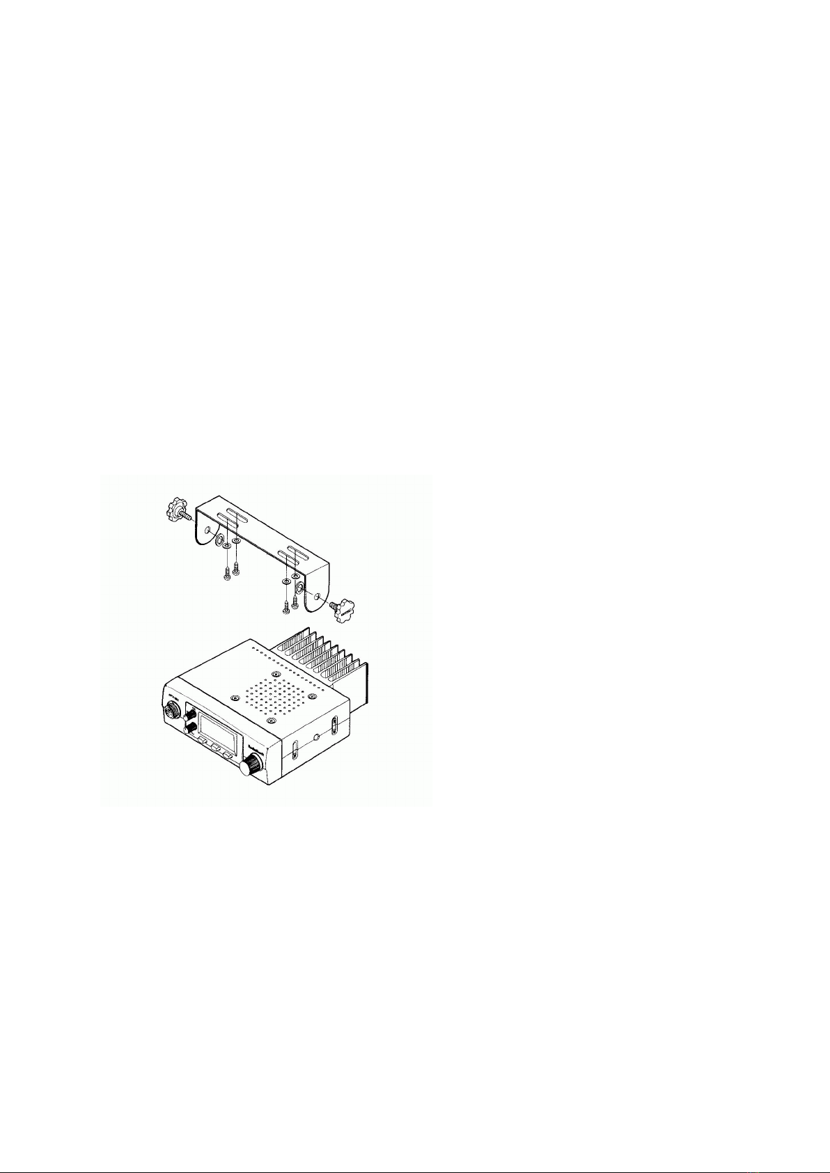
Insert the radio into the fixing device. Secure
the set ith the large knurled scre s (using the enclosed plastic ashers) firmly at the required angle.
Also mount the microphone fixing device using the enclosed scre s in an easily-accessible place. In
order to prevent interference to the vehicle electronics from transmission in the vehicle, please make
sure to follo any mounting instructions by the vehicle manufacturer for radios and antennas.
Important note: the end of the transition period of the ne European „automotive directive“ imposes
restrictions on installing and operating electronic devices in motor driven vehicles. The interpretation of
the requirements of this directive for amateur radios is not quite cleared. Some authorities request that
even radios, not primarily intended to be used exclusively in cars should have an additional e-approval
mark, hile other authorities respect a special treatment of t o ay radios under the R&TTE directive
and EMC directive ith their normal CE and alert sign marking. Some authorities request that such
radios shall not be operated hile the car is in motion and the engine is running.
Generally, the car manufacturers have the right to issue restrictions for using t o ay radios in ne
cars ( hich have been put into service since 1.10.2002). Please consult the car manufacturer and ask
for their installation hints, especially for EMC compatible antenna locations and DC connecting points.
4

Connecting to DC power
Connect the po er cable of the radio to 12 V DC po er supply of your car, motor home or boat. In
caravans or at home e recommend to use a suitable AC/ DC po er supply, capable to deliver 6-8 A at
stabilized supply voltage bet een 10.8 and 15.6 V.
If possible, do not increase cable length and connect the po er cord as close as possible directly to the
battery terminals. The cable has a looped-in glass fuse for 10 A protection. If this fuse should blo , try
to find out the reason, and replace the fuse only ith its original value and never ith ires, silver paper
or aluminum foils!
Connect the red wire with the positive + terminal, the black wire with the
negative (-) terminal of the batter .
The negative ire terminal is grounded (standard in most cars). Ho ever, do not use the car body as
negative terminal and try to connect the (–) terminal of the battery instead, herever possible! Please
note that grounding of the housing may cause electrolytic and galvanic corrosion effects in steel or
aluminum boats. Insulating of the radio housing and antenna may be necessary in such cases.
Rear side connections
Antenna selection
Mobile (car) antenna
Simple reduced size magnetic base antennas or car antennas ith indo mount or glass mount are
not the best choice for 25 W-30 W po erfull radios! Please install a po erfull VHF mobile antenna ith
grounded antenna foot. Keep maximum possible distance to passengers and place the antenna
accorcing to the car manufacturer’s instructions as far a ay as possible from sensitive electronic
circuits of the car iring. Check the good ground connection to the car body of the antenna foot.
Please remember that you and the passengers are in the immediate vicinity of a transmitting aerial,
particularly hen used as a mobile. In case you are earing a pacemaker, and the doctor or the
manufacturer of the pacemaker has recommended keeping a certain safe distance from the aerial, then
please follo their instructions!
Any antenna must be checked and aligned for best possible SWR (standing ave ratio). The final
po er amp transistor of your SY-252N is able to tolerate an SWR up to 1:2.
Use a PL 259 type plug for antenna connection. A good, VHF usable quality has teflon insulation! Do
not transmit ithout connecting the aerial and never touch the aerial during transmission!
5
Antenna socket for
PL-259 (UHF)
Po er cable assembly
12 V (13.8 V) DC
External Speaker terminal
(3.5 mm mono, 4-8 Ohms)

SY-252N as Base Station
Please respect possible restrictions in some countries (e.g. Germany), here safety distances from
antennas to other persons have to be declared hen certain output po er levels are exceeded.
For safety reasons, please do not operate this radio in high po er position (25-30 Watts RF) ith any
kind of indoor antennas. Indoor antenna radiation may interfere ith other electronic devices in the
neighbourhood of your radio.
Operation
The operating elements, knobs and buttons are located on the microphone and front panel of your
radio.
Front panel - and microphone knobs and - ke s
All knobs and keys are located in a ay so that you can key-in directly the most important
basic functions via one-touch ke s.
A second level of feature settings is available as two-touch-functions. Initially, you
ill press the FUNC key on the microphone for less than 0.5 seconds, follo ed by the
other function key
You can reach the Setup Menu, used for programming memory locations, DTMF and
CTCSS tones incl. Decoder / encoder options, repeater shift settings, beep tones and other
6

rarely used features like TOT (time-out-timer), by touching the FUNC key longer than 0.5
seconds!
Direct entr ke functions (basic functions)
To get to kno your station e recommend that you duplicate the described steps. In this chapter you
ill learn the basic functions hich you should kno about to take part in amateur radio. It is taken for
granted that you as a licensed radio amateur are familiar ith basic kno ledge of high frequency
engineering and amateur radio regulations. This is hy basic technical matters, questions of ave
propagation and regulatory issues have not been considered in this manual. You can achieve all basic
functions directly ith the help of buttons or knobs. All directly eligible functions are marked hite.
On / Off, Volume and Squelch settings
Before first use do not forget to connect microphone and antenna. Being as small as it is all operating
elements of the SY-252N have been distributed on the front panel and the microphone according to the
frequency of using them. Reception is - but ithout any special functions – possible ithout
microphone.
The unit can be s itched on or off by turning the combined VOL /OFF knob. When s itching on
for the first time choose a medium volume and turn the SQ knob to the left until you hear the
background noise.
Squelch SQ has to be adjusted so that the noise just starts to disappear. In this position
squelch ill even be opened by eak signals, it is the most sensitive position. In case you turn
squelch further to the right (clock ise) signals have to gro stronger to be s itched through.
The LC Displa of SY-252N
When s itching on for the first time a frequency is sho n on the LCD display in the middle of the band
(145.50 MHz). This is the VFO-mode.
You can select the operating frequencies by the rotar channel selector at the front panel or
the UP- / DN (do n) keys on the upper side of the microphone in programmable steps (channel
spacing). You may also use the direct keyboard entry on the microphone. Please follo this
system:
Examples:
145.7750 MHz:
Enter 4 5 7 7 5 in sequence. Omit the first leading digit „1“, hich is the same at all possible
frequencies. Do not enter the last digit „0“, because the result is already clear after entering the „5“. So
entering the last digit is not necessary.
144.8175 MHz:
Enter 4 4 8 1 7 in sequence. The radio ill add the last „5“ of the 12.5 kHz spacing system
automatically.
When s itching on for the first time the programming designated for Europe is being done already in
steps of 12.5 kHz. If you prefer a different frequency frame, i. e. in areas here there are not yet
7

frequencies in the 12.5 kHz frame, adjust your radio via the set-up menu to the desired channel spacing
system.
Push-to-talk button (PTT)
You ill find the PTT-button at the side of the microphone. For transmission you push this button for as
long as you ant to talk. When you finish talking release the PTT and your radio is automatically ready
for reception again. The correct distance to your microphone is bet een 4 and 8 cm. Speak ith the
same loudness as if you ere on the phone. Most of the radio beginners talk too loud into the
microphone! Wait a moment after having pushed the PTT before you start talking: Your transmitter has
to s itch from the reception frequency to the transmitting frequency, at your partner`s side the squelch
needs time to open! The delay can be bet een about 140 mseconds at open squelch and a max. of
300-500 msec hen CTCSS coding & decoding is applied. Thus a syllable talked too early or quickly
can be lost!
TONE CALL 1750 Hz
For repeater access most European repeaters request a tone burst 1750 Hz , appr. 1 s long. Transmit
this tone by using the
T-CALL
key at the radio front panel. T-Call is being transmitted as long as the button is being pushed.
Please do not mix up this button ith the CALL/T-SQ button at your microphone! This button operates
the CALL-channel described in the next paragraph.
Direct access to „Call“ channel
With the button
CALL/ T-SQ
you s itch from your operating channel to a previously determined call channel and back. The
manufacturer preprograms it to 145.500 MHz, the international FM-call frequency of the IARU Region I.
In case you ant to store a different frequency for the direct call channel please use the Set-up menu.
Frequenc search mode SCAN
By pushing the SCAN button the radio automatically searches for frequencies hich are being used by
other transmitters. Before starting this process please adjust squelch correctly, other ise searching
neither can be started or stopped. Preferably SCAN is being started in VFO-mode, it ill then search
the complete band. As soon as SCAN finds an already occupied channel it stops there. You ill then
hear the radio traffic on this channel for max. 6 sec. During this time you have the opportunity to either
stop scanning by touching the PTT button or by again pushing the SCAN button.
If no action is taken searching ill be continued after the aiting period. Searching can be done on VFO
frequencies or bet een memory channels depending on the mode the radio is in hen searching starts.
Recalling memor -channels ME(MR/MS)
The button ME ( Memory Recall / Memory Save) s itches directly to the stored channels (Memory
Mode). In case you already have stored freuquencies you can select these ith the rotary s itch. The
small digit ill sho the memory location number an flashing on free, unused memory locations and
continuously on hen you select a stored memory location.
Microphone lock
To prevent operation by mistake there is a small s itch at the microphone that locks all the microphone
buttons except the transmission key. This lock ill be activated by turning the sunken slide s itch on
the microphone to the right position MIC LOCK ON.
Tone call, VFO and memory buttons of the radio can still be operated.
8

Second level of functions (two-touch-functions)
The follo ing described functions all can be reached by pressing the FUNC key.
Most of these second-level functions you can recognize by the orange inscription of the keys.
The function key FUNC first has to be pressed short ( less than ½ a second). The display ill
read FUNC.
After this the desired second-level-key ill be pressed.
The FUNC display ill automatically disappear after a fe seconds or after again pressing FUNC.
MHz-ke
For tuning over larger frequency spans it is not convenient to use the rotary s itch, it may take too
many steps and too long time. Press function key FUNC. As long as y see FUNC in the display, every
step of the roatary knob becomes as large as 1 MHz – so tuning from one end to the other is no very
fast.
Activate repeater shift (offset)
Most amateur radio associations operate club-o ned automatic repeater stations located on higher
buildings or mountains. For transmitting via such repeaters, you ill need a frequency offset bet een
your receiving and transmitting frequency. When you press your PTT knob, the frequency of your
transmitter ill be shifted a certain amount versus the previous receiving frequency. Such a frequency
shift is necessary to allo parallel operation of a sensitive receiver and a po erful transmitter in the
repeater base station at the same time ithout degradation.
In amateur radio systems an international standard shift of + or – 600 kHz has been established orld-
ide. While European repeaters al ays use the lo er frequency for input, american repeaters often use
the upper shift direction, too. In Europe you ill reach all 2 m amateur repeaters ith – 600 kHz shift.
Your SY-252N allo s different repeater settings in VFO mode and memory mode.
Select desired (receiving) frequency. Press: FUNC, follo ed by SHIFT .You ill see the + icon
in the display, hen this function is used for the first time.
Repeat this procedure FUNC, follo ed by SHIFT and see the – icon
Repeating the procedure for a third time returns to initial simplex setting ( ithout shift).
Activate Tone Squelch (CTCSS)
Press FUNC , follo ed by T-SQ (at microphone).
You ill see the T icon. No Your radio transmits a CTCSS tone parallel to Your normal modulation.
You may select 38 different CTCSS tones via setup menu (next main clause). CTCSS function is only
available ith installed CTCSS module ( ill be sold as option only).
Repeat procedure FUNC follo ed by T-SQ press: display sho s no T-SQ.
No not only the radio ill transmit CTCSS tones, but also the receiver ill decode CTCSS tones. The
speaker remains silent as long as the partner station does not transmit exactly the same CTCSS code.
Only hen receiving a correctly coded signal, the speaker ill s itch on and lets You hear the
conversation.
Pressing FUNC and T-SQ once more ill s itch back to initial setting ithout CTCSS.
9

Priorit channel „Dual Watch“
Your radio allo s monitoring t o often used channels automatically in sequence.
You can al ays check the present orking frequency together ith another channel of Your memory (or
the Call channel).
Select your working frequency (VFO), e.g. 145.575 MHz
Select a second channel from Memor 1-0 or Call channel
Press FUNC, then PRI.
No the radio ill monitor hat happens on your working frequenc (in the example 145.575 MHz)
alternating ith the later selected Memor 1-0 or Call channel.
If a memory channel should have been selected as second channel, this channel may be changed even
during scanning.
Stop priority scanning via short use of the PTT button or by FUNC + PRI
Monitor ke
This key disables the squelch setting and opens the squelch as long as the key ill be kept pressed.
The feature is useful if a received signal becomes eak, or hen the receiver is muted by CTCSS in
the T-SQ setting or by DTMF decoder and you ould like to hear hat happens on the channel.
Press FUNC, follo ed by MONI and hold the key pressed. The squelch ill open after a
second and ill remain open as long as you press the key.
Complete ke locking
The complete key locking ill lock all keys except the PTT and MONI key. So it locks more functions
compared to the lock s itch on microphone.
Press FUNC and then LOCK
You ill see the icon in the display.
Unlock again ith Func + Lock
Transmit power switching Hi / Low
Press FUNC and after this for a short moment the PTT key.
The display sho s LOW as indication for reduced output po er (about 10 atts). When transmitting,
you ill see less bars of the digital meter reading.
S itch back to Hi po er by same sequence FUNC and PTT.
The icon LOW ill disappear again.
10

The Setup Menu
Some more, not frequently used functions are available via selectable Setup Menu steps. You start the
setup menu by longer pressing (longer than 0.5 sec) of the function key FUNC.
Flow-chart for the Setup Menu
FUNC key (press
min. 0.5 s)
SET MODE
FUNC key (press min
0.5 s )
STANDARD MODE
Transmit key (PTT)
Within a menu step you can select the values or actions by UP- or DOWN-keys, the rotar
switch or as far as DTMF tones and repeater shift values are concerned, by ke board.
The next menu step can be reached by subsequently pressing the FUNC key.
After the last menu step the first step ill start again.
Quit the Setup Menu by pressing the PTT-key shortly.
More about the menu steps
T-SQ : Selection of CTCSS (continuos tone coded squelch system) frequencies is possible
bet een 67.0 and 250.3 Hz. You may use the rotary s itch or up do n keys for
selection. The 38 different tone frequency follo international standards and are used
by most manufactures (compatible bet een the brands). You ill need an optional
CTCSS module (sold separately). The CTCSS unit can be installed by plug-in after
opening the upper cabinet (no soldering or adjustment required). CTCSS is used to
create closed user groups in a radio net ork, here all transmitting stations transmit
the same lo audio signal frequency parallel to microphone modulation. This is called
encoder function, here the display sho s T only. The receiving party can decide
hether they ant to listen to all radio traffic or only to radio traffic of the same user
11
T-SQ
MEMORY
DTMF
dA ON/OFF
dt (DTMF)
ON/OFF
+,- SHIFT
bP (BEEP)
ON/OFF
rb (Roger)
ON/OFF
StEP
toT
These menu steps appear
only if the corresponding
module(s) (CTCSS and / or
DTMF) are installed.

group. In that case the decoder ill be activated. Speaker ill be on only if the
received signal carries the correct DTMF tone.
In that setting the display ill sho T-SQ. Compared to Europe, CTCSS is more
familiar in USA, here most repeaters use it for selectable functions.
Note: European repeater station are –in most cases- not transparent for CTCSS. This
means, that received CTCSS signals are normally not transfered to the transmitter.
This ould require special decoders, encoders or regenerators. As a consequence,
CTCSS cannot be used if a conversation ill use a standard repeater not specially
equipped for CTCSS. You may have a better chance if you use the highest CTCSS
frequencies- test it from case to case.
MEMORY : Programming of memor channels for frequent use. Before entering the setup
menu, you should select the desired operating frequency in VFO mode, repeater
shift and CTCSS setting. You can store a complete setting into each of the 10
memory locations. All settings can be different!
Start setup menu by FUNC longer than 0.5 sec. Memor is the first menu step.
ME is flashing. A memory location number appears belo ME (1-0 or C for the
call channel). Free location numbers are flashing!
Select the memory location ith up / down or rotar knob.
Press ME(MR / MS) at the radio front panel for saving the complete setting under
this location number.
A successfully saved memory location number ill not flash any more and ill remain
continuously on!
Erasing memor locations
Recall the memory channel You ant to erase.
Start the setup menu step for memory (FUNC longer pressed, first setup menu
step ME appears)
Press ME(MR / MS) at the radio’s front panel
After erasing the memory location, the location number ill flash again.
DTMF: You can store up to 10 different standard numbers (similar to a phone number). Each
number can have up to 5 digits. You can select one of these numbers for auto
transmission, as soon as PTT ill be pressed (next menu step dA, DTMF automatic),
or You use one of the numbers for Your o n DTMF decoder (menu step dt MF on /
off, see belo ).
Select address (1-0) first by Up / Down or rotar knob
Enter the number (1 to 5 digits) digit by digit using the keyboard (e.g. 12345).
Store setting ith DTMF key on microphone.
dA: Activate (oN) or deactivate (oF) automatic DTMF transmission by means of Up /
Down-selection. If activated, the previously selected DTMF number ill be transmitted
at the beginning of each PTT pressing. This is used e.g. for selective calling, if the
other party has a decoder.
Notes about DTMF:
You may also manually transmit one or more single DTMF tones as digits of a „phone number“ ith
Your keyboard. Press and keep PTT button pressed at first. While still transmitting, enter the desired
DTMF digits into keyboard. Each digit ill be transmitted as long as the digit ill be pressed. Most
selective calling systems used in amateur radio accept manually entered numbers ithout problems. As
a special add-on your AE 540 is even able to transmit the additional DTMF digits A, B, C and D, so
together ith 1-0, *, # you have 16 different DTMF tone pairs.
12

dt If activated (DTMF oN), the speaker of your radio ill be muted. If the distant party ill
transmit Your decoder number (e.g. 12345), the speaker ill s itch on and You can
hear the transmission. This performs a selective calling system.
+,- SHIFT Selection of the repeater offset (frequency shift). Amateur radio repeaters use 600 kHz
orld- ide. The display ill sho 60, 1 digit less. The value can be changed for
special purposes bet een 100 kHz and 8 MHz. Commercial radio net orks in Europe
(e.g. PMR or VHF marine radio) ill use 4 6 MHz (= 4600 kHz, 460 in display).
bP (Beep) s itches keyboard tones on and off.
rb (Roger Beep): activates or deactivates automatic-over-signal in transmitter after
releasing PTT knob.
st (Step): select the desired channel spacing system for better tuning. Channel spacing
systems may be different among the radio services. Recently, amateur radio in Europe
has applied the 12.5 kHz system (default). Note: After a reset the radio ill start ith
20 kHz spacing and must be reprogrammed to 12.5 kHz again.
Please select the 12.5 kHz or 25 kHz spacing system for european applications.The
technical parameters of this radio correspond to the system requirements of a 25 kHz
spacing system ith reduced FM peak deviation.
You can change the channel spacing settings any time, but it is recommended to start
al ays on an even frequency like 145.000 MHz fitting into all spacing systems (and
not for example ith 145.010 MHz) to avoid rong steps or un anted frequency offsets
to (Time-out-Timer): setting for the maximum possible transmit time. If You should keep
the PTT button pressed longer as adjusted in this menu step, the transmitter ill s itch
off until You release the PTT button again. Some minutes are reasonable as setting for
amateur radio. The value 10 means 10 minutes allo ed continuous transmit time. The
TOT can avoid accidental or unintended blocking of hole net orks caused through
defective PTT buttons. Maximum TOT time is 30 minutes.
Note: All DTMF and CTCSS functions are only available in the setup menu, if the appropriate
modules are installed inside the radio. Please note that the radio does not come ith
installed CTCSS and / or DTMF sub boards. The setup menu ill skip menu steps
belonging to uninstalled options.
Terminating the setup menu
Return to normal operation at any time by pressing FUNC or PTT for a short moment. The display ill
change to normal frequency or memory channel display. In the 5, 15, 12.5 und 25 kHz channel spacing
systems you ill see the kHz and 100 Hz digits smaller at the right side of the 10 kHz digits.
Displa Channel Spacing Application
5 5 kHz steps For non-standard offset
frequencies
10 10 kHz steps For non-standard offset
frequencies
12.5 12.5 kHz steps Europe (ne system), many
commercial users
15 15 kHz steps USA (15 und 30 kHz spacing)
20 20 kHz steps USA, Asia, (commercial radio in
Germany)
25 25 kHz steps Former European system,
international VHF marine radio
13

Reset to factor default settings and erasing all memories
A general reset to factory default settings may become necessary hen the unit sho s abnormal
functions or behaviour. If any malfunction should occur, try first to reset the radio, before returning it to
Your distributor for repair.
To perform a general reset
S itch he radio off and on again hile T-Call/Shift key is kept pressed
The radio starts ith factory default setting in a 20 kHz spacing system
During reset all personal settings (memories etc) are erased
Note: The reset is not possible in modes 3, 6 and 7, because the user shall not have any access to the
settings. If a reset in one of these modes should become necessary, open the radio, take out all
jumpers and perform the reset. If the radio should no ork again, repeat the customer settings (e.g.
memory storings) and add the jumpers again.
Technical informations
Saving and backup of user settings
This radio does no more need a lithium battery or any other backup medium ith limited lifetime. It uses
EEPROM backup technology. During each s itch off procedure the CPU ill load all present settings
into the EEPROM and recall these information during the next po er on process. The EEPROM
backup does not need any electrical po er for data backup and lasts for many thousands of backup
procedures.
Please take care that You s itch the radio po er at first or only via the radio’s ON / OFF volume
knob and not by simple disconnecting of the external po er supply (like ignition s itch, po er supply
mains s itch).
Connecting points for accessor items
Microphon wiring:
8 pin type mic socket. The microphone contains DTMF and other keys and a microcontroller for data
transmission bet en microphone and radio. Please operate the radio only ith the original microphone
supplied ith the radio, because some function can only be reached ith the original keyboard. The
audio input is connected via PIN 1, in series ith a PTT key- ired as normally used in hand held
radios hich have a common wiring for MIC and PTT. If used for packet radio modems, the modem
audio output should be isolated from DC via coupling capacitor in series, hile the modem PTT can be
connected via series resistor 2.2 kOhms to the same PIN 1. Ground is connected to PIN 8.
Please do not use any other PIN of the mic socket for audio purposes.
Ext. Speaker socket
An external speaker should have 4-8 Ohms impedance and minimum 2-4 Watts. The socket is a 3.5
mm mono type. Inserting an extension speaker ill automatically s itch off the internal speaker.
Note to packet radio modem connection
The mic socket does not provide any audio output signal suitable for modem decoders, because the
radio is only intended for normal speech transmission. Ho ever, connecting an up to 1200 bit/sec
Packet Radio data modem ill require an audio output signal from the receiver, hich can be taken
from the ext. Speaker socket only. Modulation input is available at PIN 1 of the mic socket as described
in the MIC socket clause. We cannot recommend to connect modems ith higher transmission data
rate.
14

Programming different options (for service onl after opening the cabinet)
Jumper settings truth table
The radio is shipped ith a factory default setting to 136-174 MHz maximum possible operating range
(Mode 0, no jumper inserted). The switchable frequency range can be limited by hard are jumper
setting to 144-146 or 144-148 MHz ith different receiving ranges according to the follo ing jumper
setting truth table. You may solder jumper contacts or use plug-in jumpers (same jumpers are used in
computer main boards, or as jumpers on ATAPI CD or hard disk drives.
MODE Jumper settings TX RX
C 3 C 2 C 1
0 - - - 136.000 - 174.000MHz 136.000 - 174.000MHz
1 yes - - 144.000 - 147.995MHz 136.000 - 174.000MHz
2 - yes - 144.000 - 145.995MHz 144.000 - 145.995MHz
3 yes yes - VFO mode deactivated
(for commercial users, no amateur radio) *
4 - - yes 144.000 – 145.995 MHz 136.000 - 174.000MHz
5 yes - yes 146.000 - 174.000MHz 146.000 - 174.000MHz
6 - yes yes Slave (for commercial use only)**
7 yes yes yes Master (for commercial use only)**
- means: no jumper inserted or soldered (contact pair open).
es means: jumper is plugged in or soldered.
*In mode 3 all ke s exept the rotary s ich and the PTT button are disabled. The rotary
s itch allo s only the selection of previously programmed memory locations (maximum
10 frequency settings). This mode is designed for use as commercial radio in
countries, here SY-252N is allo ed to be used for PMR purposes, or for amateur use
hen malfunctions caused through user errors shall be excluded. For programming,
start in Mode 0 (no jumper), store the desired frequency settings in one or up to 10
memory locations. S itch the radio off and insert the jumpers for mode 3. After
s itching on again, user can only use the pre-programmed memory locations. Even a
hard are reset cannot delete these settings.
** This function is reserved for a special PMR application in countries, here this radio is
allo ed to be used in commercial net orks.
Safet precautions: to avoid possible problems caused through electrostatic discharges (ESD effects),
please s itch the radio off before opening the cabinet. Discharge all Your tools and Your hands against
ground before inserting or changing the jumpers inside. There is no reset required after jumpers have
been reconfigured! Just s itching off and on again activates a ne jumper setting. You ill find the 3
jumpers just above the volume potentiometer on a Sub PCB in 90 ° angle to ards front panel. Jumper
C1 is a ay from front panel, jumper 3 is close to front panel, Jumper 2 is in the middle bet een the
others.
15

Technical data SY-252N
Frequency ranges (depending on programming) max. 136- 174 MHz
Frequency stability +/-1.5 kHz
ITU transmission designator 14KF3E ith preemphasis
Allo ed supply voltage tolerances 10.8 to 15.6 V DC
Allo ed operating temperature range -10 to + 55 ° C
DC fuse 10 A (US-Type glass fuse, inserted in
cable fuse holder)
Programmable memory channels 10 + 1 CALL-channel
Selectable channel spacing systems 5, 10, 12.5, 15, 20 & 25 kHz
Transmitter output po er High 25-max.30 Watt (tolerances 22..30W)
LOW 10 W
Transmitter spurious response min. 60 dB belo carrier
Microphone sensitivity appr. 4 mV / 1 kOhm
Mikrophone type electret ith keyboard
Max. frequency deviation for speech default setting max. 2.8 kHz
Tone Call 1750 Hz default setting appr. 2.5 kHz deviation
CTCSS (option, sold separately) 38 frequencies, appr. 400 Hz deviation
DTMF selective calling (option, sold separately) encoder /decoder manual (keyboard)
automatic (up to 5 digits) via menu
Repeater shift (repeater offset) - / + 600 kHz default,
programmable up to 8 MHz
Current consumption TX appr. 6 A (high)
appr. 4.5 A (lo )
Current consumption, RX
Standby, squelch open, medium volume appr. 800 mA
Receiver sensitivity for 12 dB SINAD
Measured at 3 kHz FM deviation in 144-146 MHz range better than -16 dBµV
Adjacent channel selectivity appr. 55 dB (25 kHz channel spacing)
appr. 45 dB (12.5 kHz spacing)
1. receiver I.F. 21.4 MHz
2. receiver I.F. 455 kHz
Audio Output Po er (at 10 % THD) min. 2.4 W at 8 Ohms
Audio frequency response 400Hz- 2700 Hz / -3 dB
Dimensions 130 mm x 35 mm x 140 mm
Weight appr. 0.5 kg
16
Table of contents