Drainvac CYCLONIK Series User manual

MAN.CYC.AN
PRINTED IN CANADA (02-21)
OWNER’S MANUAL
CYCLONIK SERIES
Cleaning Systems

Central Vacuums
Central Vacuums
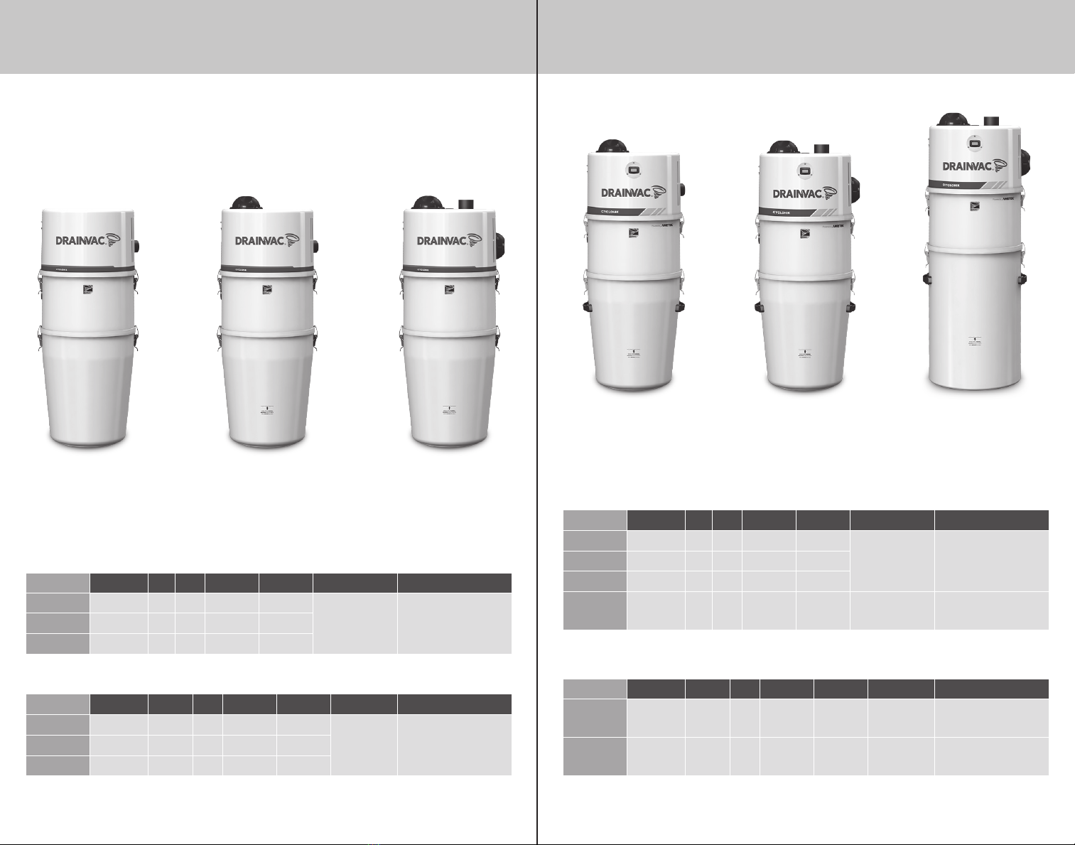
The compact series’ models
do not comply with NFPA standards.
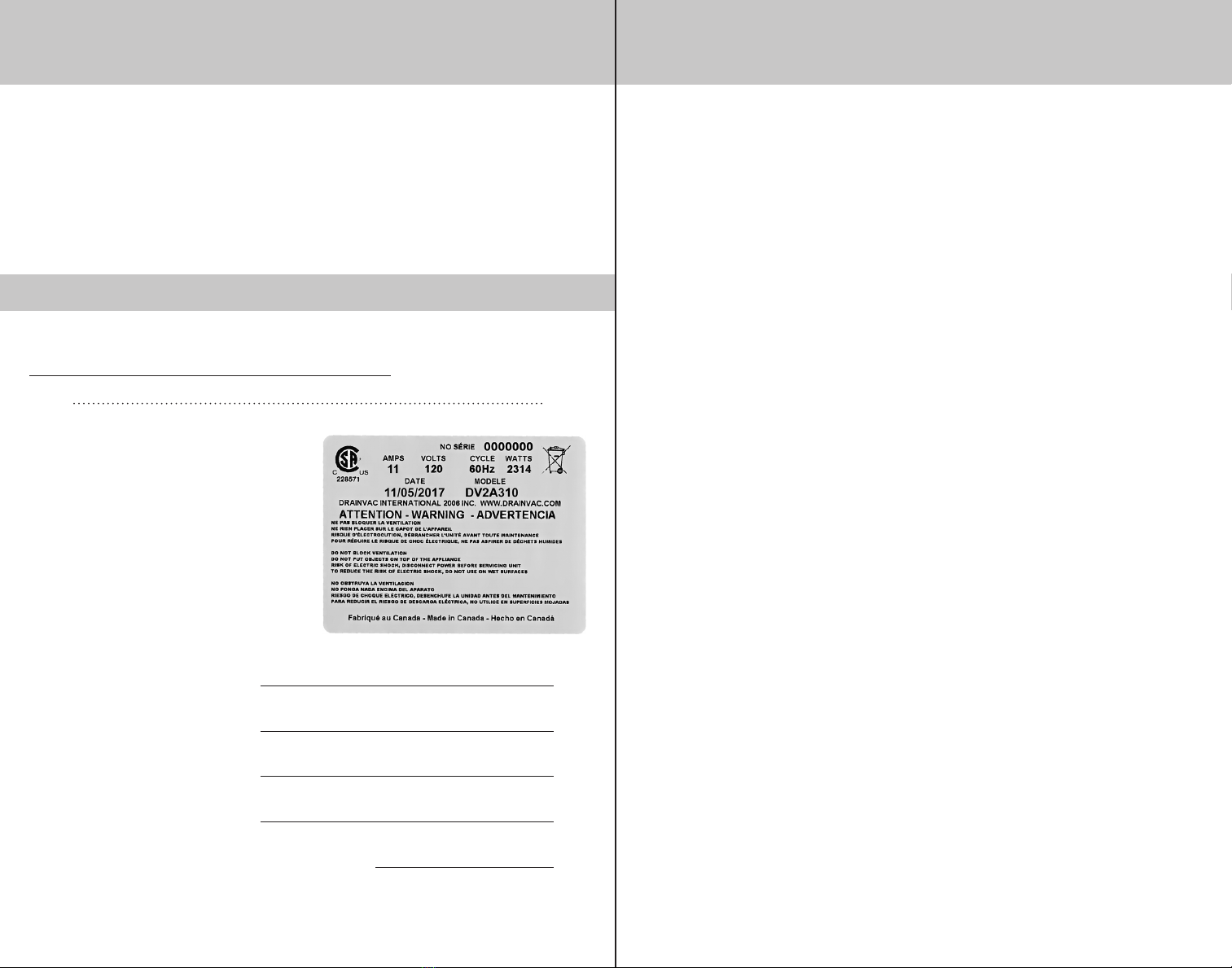
IMPORTANT SAFETY INSTRUCTIONS
When using an electronic appliance, basic safety precautions should always be
followed. Read all guidelines before operating the unit.
To reduce risk of fire, electric discharges or injuries :
• Use this vacuum only for its intended use as described in this manual. (Use of
attachments not recommended by the manufacturer may cause fire, electric shock,
injury or damage to system components.)
• Do not allow vacuum to be used as a toy. Close supervision is necessary when this
vacuum is used by or near children.
• Do not leave the unit running without any supervising. Disconnect the unit if it is not
used and before maintenance.
• The Cyclonik series is designed to pick up small quantities of liquids only, up to 16 L
(3.5 imp. gal.). However, models DV1R800 and DF1R630 cannot pick up any liquid.
• Do not pick up anything that is burning or smoking, such as cigarettes, matches, or
hot ashes.
• Do not pick up any flammable liquids or combustible materials (gasoline, fuel, diesel)
hot debris, waste solvents (paint or other), explosive materials that would cause
harm to the vacuum cleaner.
• Do not vacuum drywall dust or baking flour as it may cause damage to your vacuum.
• Avoid picking up hard or sharp objects to prevent damaging or block the hose and
the plastic pipes.
• Do not put any object into openings. Do not use if an opening is blocked. Keep free
of dust, lint, hair and anything that may reduce airflow/suction. Lack of air flow will
cause the motor to overheat.
• This vacuum cleaner creates suction. Keep hair, face, fingers, all body parts and
loose clothing away from any openings.
• Never operate without dust bag and/or filter in place.
• Never plug in a unit designed to operate with a current of 120V in a 230V outlet and
vice versa.
• If the power cord is damaged, it must be replaced by a special cord available from
the authorized local dealer/distributor.
• Do not use extension cords or outlets with inadequate current carry capacity.
• Never operate this vacuum if it has a damaged cord or plug, if it is not working
properly, or if it has been dropped or damaged. Return to authorized dealers/
distributor for repairs.
• Never handle plug, cord or power units with wet hands.
• Never disconnect plug by pulling cord. To disconnect from the outlet, grasp the plug,
not the cord.
• Connect to a properly grounded outlet only. See grounding instructions.
• Keep cord away from heated surfaces.
• Turn off all controls before unplugging.
• Hoses with electrical connections must not be used if damaged.
By overlooking safety rules, you might risk putting your health in danger and to those
who surround you!
Drainvac disclaims any responsibility should you infringe upon these guidelines.
SAVE THESE INSTRUCTIONS

4 5
INTRODUCTION TABLE OF CONTENTS
We wish to thank you for your trust and congratulate you for having chosen a Drainvac
product. It is a sound investment that will satisfy your vacuuming needs for years to come.
Drainvac’s central vacuum cleaners are manufactured and checked at our factory by our
qualified staff who have been specifically trained to this end. A number of installations
and operating methods must be followed to ensure your system’s maximum performance
and to avoid unnecessary service calls. Please read this manual carefully.
First off, we recommend you to fill out
this form before you start the installation
process. If you have any concerns or
problems you may encounter, please
contact the nearest retailer. The unit’s
profile will be required.
To fill in the Drainvac product registration form, go to
www.drainvac.com/client-support/register-your-drainvac
Model* :
Serial number* :
Retailer name :
Date of purchase:
Date of the last maintenance:
*This information is found on a metal tag located on the left side of the unit.
Metal tag
REGISTRATION
MODEL TYPE .................................................... 6-7
UNIT DESCRIPTION. . . . . . . . . . . . . . . . . . . . . . . . . . . . . . . . . . . . . . . . . . . 8-13
INSTALLATION
FIRST THINGS FIRST.................................................. 14-15
MOUNTING THE UNIT TO THE WALL .................................... 16-17
CONNECTING THE DUST INLET............................................17
AUDIOPROTEK MUFFLER / AIR OUTLET................................. 18-19
PIPING INSTALLATION
GENERAL NOTES.................................................... 20-21
INSTALLATION DIAGRAM..............................................22-24
EXAMPLES OF PROPER AND IMPROPER INSTALLATIONS .................25-27
ELECTRICAL POWER SUPPLY
PROCEDURE / EXAMPLES OF PROPER AND IMPROPER INSTALLATIONS ...... 28
DIAGRAMS OF AN APPROPRIATE CONNECTION ............................ 29
GROUNDING INSTRUCTIONS............................................. 30
MAINTENANCE PROCEDURES............................ 30
WEEE GUIDELINES .............................................31
TECHNICAL PROBLEMS / SUPPORT................... 32
ANNEX
ANNEX I (CIRC02)
ANNEX II (CIRC03)
ANNEX III (CIRC18)

6 7
INTERNATIONAL (220V - 240V) INTERNATIONAL (220V - 240V)
MODEL TYPE MODEL TYPE
You have purchased one of the following models. Identify the one related to it.
The model number is marked on the label stuck on the left side of the head.
RESIDENTIAL SERIES
NORTH AMERICA (108V - 120V)
COMMERCIAL SERIES
NORTH AMERICA (108V - 120V)
MODELS AIR WATTS H2O CFM DECIBELS AMPS GAL./L SIZE in / cm
DV1R12-CT 700 145 136 62 11.6
10 / 46 15 dia. x 38 /
38 dia. x 95
DV1R15-CT 2 x 355 160 111 70 18
DV1R800 800 138 138 60 14
MODELS AIR WATTS mmH2O m3/h DECIBELS AMPS GAL. / L SIZE in / cm
DF1R11 483 3148 207 66 7
10 / 46 15 dia. x 38 /
38 dia. x 95
DF1R15 2 x 355 4191 198 70 10.8
DF1R630 700 3880 315 58 7
MODELS HP H2O CFM DECIBELS AMPS GAL./L SIZE in / cm
DV1R12-CTTM 2.1 145 136 62 11.6
10 / 46 15 dia. x 38 /
38 dia. x 95
DV1R15-CTTM 3 160 111 70 18
DV1R19-27CT 3.9 181 122 70 22
DV1R20-27CT 3.9 181 122 70 22 12 / 54 15 dia. x 51 /
38 dia. x 130
MODELS HP mmH2O m3/h DECIBELS AMPS GAL. / L SIZE in / cm
DF1R19-CT 3.46 4191 198 70 10.8 10 / 46 15 dia. x 38 /
38 dia. x 95
DF1R20-CT 3.46 4191 198 70 10.8 12 / 54 15 dia. x 51 /
38 dia. x 130

8 9
DV1R12-CT / DV1R12-CTTM* DV1R15-CT / DV1R15-CTTM* / DF1R15
UNIT DESCRIPTION
Exhaust muffler
UNIT DESCRIPTION
Canister
Audioprotek muffler
24V plug
Power cord
Power cord
Canister
24V plug
Exhaust muffler
Audioprotek muffler
Audioprotek muffler
*The DV1R12-CTTM model has an hour meter. *The DV1R15-CTTM model has an hour meter.

10 11
DF1R11DV1R800 / DF1R630
UNIT DESCRIPTION UNIT DESCRIPTION
Exhaust muffler
Canister
24V plug
Power cord Foam filter
Exhaust muffler
Canister
Audioprotek muffler
24V plug
Power cord

12 13
DV1R19-27CT / DF1R19-CT DV1R20-27CT / DF1R20-CT
UNIT DESCRIPTION UNIT DESCRIPTION
Power cord* Power cord*
Canister Canister
24V plug 24V plug
Exhaust muffler Exhaust muffler
Audioprotek muffler Audioprotek muffler

14 15
12’’ (30cm)
24’’ (60cm)
10’’
(25cm)
51’’ (130cm)
INSTALLATION
- FIRST THINGS FIRST -
REQUIRED TOOLS
Philips Screwdriver
Cutting Pliers Measuring Tape Hole saw 2.25”
(57 mm)
Drill 0.5”
(12.5 m) bit
Mitre box and saw PVC Pipe Cutter
2” (50 mm)
Regular Screwdriver5/16” Socket
Head Screwdriver
or
INSTALLATION
- FIRST THINGS FIRST -
WHERE TO INSTALL THE UNIT
We recommend installing the system on the lowest level of the building to avoid having
to work against gravity. Dust and solids will fall easier than being pulled upwards, this
is why the basement is generally the most ideal location. If there is no basement, the
garage or a storage room will do.
MINIMUM DIMENSIONS AND SPACING
It is important to install the unit in a location where it will be easily
accessible for maintenance and to effectively evacuate dust. The
minimum spacing required is the following:

16 17
INSTALLATION INSTALLATION
Gypsum
Board
Wood
Panel
Wall Stud
• Attach the bracket to the wall with the 5 screws supplied with the head.
If the wall includes wall studs covered with gypsum board, we recommend
installing a wooden panel screwed to the wall studs beforehand for more stability.
Cut the
fastener
1) MOUNTING THE UNIT ON THE WALL
• Undo the fastener securing the wall bracket and base at the
back of the unit with cutting pliers.
Suggested distance from the floor:
50” (125 cm)
• Lift the unit and slide its
support onto the wall bracket.
2) CONNECTING THE
DUST INLET
• Connect the dust inlet onto the unit
securing it with a collar (do not glue).

18 19
INSTALLATION INSTALLATION
3) AUDIOPROTEK MUFFLER
All Cyclonik systems are supplied with Audioproteks,
except for models DV1R800 and DF1R630.
• Instructions on how to assemble the Audioprotek mufflers are included in a leaflet
inside the packaging.
4) AIR OUTLET
An air outlet leading outside the building is mandatory for all Cyclonik systems,
except for models DV1R800 and DF1R630, which you can install an Activac 3 filter.
MUFFLER
• Connect the air outlet to the unit, securing it with a clamp and install the muffler
with a second collar (do not glue).
ACTIVAC 3
• Clamp the 90oshort elbow to the unit
with the supplied collar and insert
the Activac3 filter to the other end
with a second collar (do not glue).
2 motor unit1 motor unit
Installation with a straight pipe.
Straight muffler Straight muffler
Curved muffler
Installation with a 90oelbow.
STEEL MUFFLER
Some units are equipped with a steel muffler to absorb the noise produced
by more powerful systems. Unlike plastic mufflers, this steel muffler must be
installed on the wall.
• You will find the installation method on the sheet provided with the exhaust.
Steel Muffler

20 21
Figure A Figure B
Figure C Figure D Figure E
PIPING INSTALLATION
The following pages illustrate piping diagrams, typical installations and the parts that
we recommend for an optimum performance of your central vacuum system.
GENERAL INFORMATION
• You must plan to install an air outlet leading outside for these units but make
sure that the evacuated air does not lead under a carport.
• If your unit includes two motors, it is important to use metal piping and couplings
for the air outlet.
• To determine where to locate the wall inlets, use the length of the vacuum hose as
a basis, measuring the furthest point from the wall where the wall inlets are to be
installed. Do the same for all the wall inlets until all areas of the house or building
can be reached with the vacuum hose, by moving it from one wall inlet to another;
don’t forget to install one in the garage or outside to vacuum your car.
• If your walls are made of gypsum board, never install a wall inlet in the centre of
the wall. Drill the holes for the wall inlets close to a wall stud or a door frame.
• Any screw length can be used if you install the piping as illustrated in Figure A.
If you install the piping as illustrated in Figure B, make sure to position the small
screw in the right place to avoid piercing a hole through the pipe.
• The minimum cornering pipe must be at least a medium elbow, but an 45opipe is
recommended for all corners for an optimal efficiency.
• Always use a short elbow when connecting the wall inlets (Figures A and B) to
prevent long objects (for example, a pencil) that may have been vacuumed by
mistake from blocking the piping further on.
• The pipes leading upwards must be slightly higher than the main pipeline to
prevent liquids from flowing back down (Figure C).
PIPING INSTALLATION
Small screw
Short elbow

22 23
Inclinaison
DIAGRAM OF A RESIDENTIAL INSTALLATION DIFFERENT INSTALLATION POSSIBILITIES
On the top floor
(at the end of a pipeline)
On the first floor
(connected above a
pipeline under the floor)
On an intermediary floor
Always have a slight
inclination of the piping
towards the unit.
PIPING INSTALLATION WEEE GUIDELINES
Dry pipeline
Wet pipeline
Exhaust pipeline
In the basement
(connected under a
pipeline under the floor)
Back-to-back
On the first floor
(connected above a
pipeline under the floor)
On the top floor
(at the end of a pipeline)
On an intermediary floor

24 25
Joint with inside stoppers
Thin wall
Thick wall
For wall plates only
Smooth joint without
inside stoppers
EXAMPLES OF PROPER
AND IMPROPER INSTALLATIONS
PIPING INSTALLATION
DIAGRAM OF A COMMERCIAL INSTALLATION
Installation example in series
Always have a slight inclination of the piping towards the unit.
Under the floor
Through the ceiling
PIPING INSTALLATION
Inclination
Inclination

26 27
EXAMPLES OF PROPER
AND IMPROPER INSTALLATIONS
PIPING INSTALLATIONPIPING INSTALLATION
EXAMPLES OF PROPER
AND IMPROPER INSTALLATIONS

28 29
ELECTRICAL POWER SUPPLY
DIAGRAMS OF AN APPROPRIATE CONNECTION
If you experience voltage surge problems on your electrical circuit in spite of adequate
connections, a high magnetic circuit breaker can be installed on your electrical panel.
Contact an electrician for more information.
24V wires (supplied with the unit)
DV1R800 : 15 amp circuit / 108V - 120V
DV1R12-CT : 15 amp circuit / 108V - 120V
DV1R15-CT : 20 amp circuit / 108V - 120V
DV1R12-CTTM : 15 amp circuit / 108V - 120V
DV1R15-CTTM : 20 amp circuit / 108V - 120V
DV1R19-27CT : 30 amp circuit / 108V - 120V
DV1R20-27CT : 30 amp circuit / 108V - 120V
ELECTRICAL POWER SUPPLY
CONNECTION PROCEDURE
EXAMPLES OF PROPER
AND IMPROPER INSTALLATIONS
24-volt wires
An electrical cord is equipped to all central vacuum systems. An adequate electrical
power outlet must be installed near the unit. We strongly recommend installing an
electrical circuit which will only be used for the unit.
• Install the 24-volt wires from
the network (each wall inlet) to
the unit.
• Connect the unit to the
electrical outlet with the
power-supply cord.
• The unit is now ready to be used.
DF1R630 : 10 amp circuit / 220V - 240V
DF1R11 : 10 amp circuit / 220V - 240V
DF1R15 : 15 amp cicuit / 220V - 240V
DF1R19-CT : 15 amp cicuit / 220V - 240V
DF1R20-CT : 15 amp cicuit / 220V - 240V

30 31
Figure F
MOTOR BRUSHES
Any mechanical system requires a minimum of maintenance and your system is no
exception to the rule. We therefore recommend that you have your motor brushes
inspected after 500 hours of use to check how worn they are and to replace them if
need be.
On average, this inspection should occur:
• For residential applications: once every 3 to 5 years
• For commercial applications: once or twice a year
When the time comes, contact your retailer or distributor for this maintenance procedure.
This unit complies with the WEEE (Waste Electrical and Electronic
Equipment) Guidelines, which promote the recycling of this type of
waste equipment and encourage the development of products that are
adapted to efficient waste reclamation at the end of their life cycle.
The WEEE Guidelines stipulate that the original supplier should agree
to reclaim any obsolete equipment free of charge. We recommend that
you advise your supplier that you would like him to reclaim your unit when you order
and replace it with a new one.
Do not discard the unit with your regular garbage. The symbol representing a garbage
bin on wheels on the unit’s label (Figure F) attests to this requirement. You must ensure
that, at the end of its life cycle, your unit is reclaimed, treated and recycled by an
authorized firm.
For more information, contact your municipal waste management department.
The acquirer of the auxiliary heads is committed to respect the
environmental regulations of the liquid and solid waste disposal
in the public water system.
MAINTENANCE PROCEDURES
CARTRIDGE FILTER
You must clean the cartridge filter every 6 months to prevent your unit from losing any
suction power and extend its lifespan. CAUTION: If your unit runs with a cartridge filter
and the filter was removed for cleaning purposes, it is important not to use the unit or
you will damage the motor.
• The cartridge cannot be washed. Clean with compressed air or replace it.
WEEE GUIDELINES
ELECTRICAL POWER SUPPLY
Grounded
Outlet
Grounded pin
GROUNDING INSTRUCTIONS
These units must be grounded. If it should malfunction or breakdown, grounding
provides a path of least resistance for electric current to reduce the risk of electric
shock. This appliance is equipped with a cord having an equipment-grounding conductor
and grounding plug. The plug must be inserted into an appropriate outlet that is
properly installed and grounded in accordance with all local codes and ordinances.
WARNING - Improper connection of the equipment-grounding conductor can result in
a risk of electric shock. Check with a qualified electrician or service person if you are in
doubt as to whether the outlet is properly grounded.
DO NOT MODIFY THE PLUG PROVIDED WITH THE UNITS -
IF IT DOES NOT FIT THE OUTLET, HAVE A PROPER OUTLET INSTALLED
BY A QUALIFIED ELECTRICIAN.
These units are for use on a nominal 108V - 120V or 220V - 240V circuit and has a
grounding attachment plug that looks like the one illustrated below. Make sure that the
electrical cord is connected to an outlet having the same configuration as the plug.
NO ADAPTOR SHOULD BE USED WITH THIS APPLIANCE.
*Illustration of a north-americain electrical outlet

32
SUPPORT
CONTACT
24 VOLTS
# 1
MOTOR /MOTEUR
N
NEUTRAL /WHITE WIRE
NEUTRE /FIL BLANC
LED
SWITCH
ON/OFF
INTERRUPTEUR
SWITCH
ON/OFF
INTERRUPTEUR
MOTOR # 1
MOTEUR # 1
LINE IN /BLACK WIRE
ALIMENTATION ENTRÉ /FIL NOIR
110-120 VOLTS
THE UNIT WON’T START UP...
SOLUTION :
1) Check if the LED is lit.
2) Check the circuit breaker in your electrical panel.
3) Check the unit’s circuit fuse/breaker.
4) Check the 24-volt circuit, as follows :
Establish an electrical contact between the two 24V circuit terminals of the unit with a
metal object such as a screwdriver or a coin.
• If the unit starts up, either the 24V wire is cut or disconnected from one of the
wall inlets, or the hose is defective.
• If the unit does not start up after all theses steps, the printed circuit is defective.
THE UNIT WON’T SHUT DOWN…
SOLUTION :
Check the 24-volt circuit as follows :
Disconnect one of the two wires on the unit’s 24-volt circuit.
• If the unit shuts down, the problem could be that two 24-volt wires are touching
themselves somewhere or that the wall inlet is defective.
• If the unit doesn’t shut down, the printed circuit is defective.
Unplug the power cord.
TECHNICAL PROBLEMS
If you wish to speak with a customer service
representative, please contact your supplier/dealer.
To find a retailer near you, please visit our website.
ANNEX I
CIRC02
CONNECTION DIAGRAM
108-120 VOLTS
DV1R12-CT, DV1R800, DV1R12-CTTM,
DV1R19-27CT, DV1R20-27CT

L1
GND
M1_GND
M2_GND
M2_L2
M1_L2
M2_L1
M1_L1
L2
LED
LOW VOLTAGE
BAS VOLTAGE
RESPECT POLARITY
RESPECTER LA POLARITÉ
#1
MOTOR/MOTEUR
L
#1
MOTOR/MOTEUR
N
#2
MOTOR/MOTEUR
N
GROUND - GREEN WIRE
MISE À LA TERRE - FIL VERT
NEUTRAL / NEUTRE
LINE IN / ALIMENTATION ENTRÉE
GROUND
MOTOR/MOTEUR #1
GROUND
MOTOR/MOTEUR #2
#2
MOTOR/MOTEUR
L
NEUTRAL /WHITE WIRE
NEUTRE / FIL BLANC
LED
CONTACT
24 VOLTS
SWITCH
ON/OFF
INTERRUPTEUR
SWITCH
ON/OFF
INTERRUPTEUR
MOTOR # 1
MOTEUR # 1
# 1
MOTOR/MOTEUR
N
MOTOR # 2
MOTEUR # 2
LINE IN /BLACK WIRE
ALIMENTATION ENTRÉ /FIL NOIR
# 2
MOTOR/MOTEUR
N
ANNEX III
CIRC18
CONNECTION DIAGRAM
220-240 VOLTS
DF1R630, DF1R11, DF1R15,
DF1R19-CT, DF1R20-CT
ANNEX II
CIRC03
CONNECTION DIAGRAM
108-120 VOLTS
DV1R15-CT, DV1R15-CTTM

Central Vacuums
This manual suits for next models
12
Table of contents
Other Drainvac Vacuum Cleaner manuals