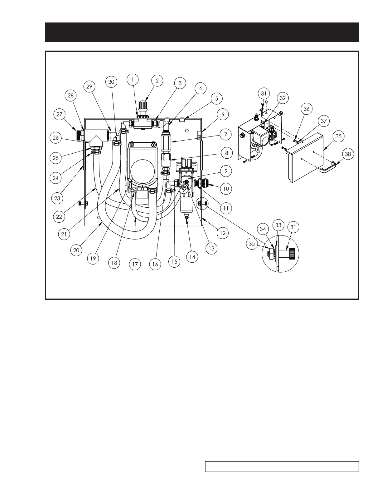
Dramm FM50 User manual

FOAMER
FM20 /FM50 Fo mer
®
Owners M nu l
FM50
FM20

Tabl of Cont nts
Printed in the U.S.A. Revised: 12-2020
Warranty ............................................................................3
Safety & Set-Up Instructions ..............................................4
Air Fitting Information ........................................................4
Operation & Useable Products ............................................5
After Use Instructions..........................................................6
Troubleshooting ..................................................................6
Box Assembly Diagram ........................................................7
Box Parts List ......................................................................8
Hose Assembly Diagram & Parts List ..................................9
F 20 Plumbing Assembly Diagram & Parts List ................10
F 50 Plumbing Assembly Diagram & Parts List ................11
F 20 Frame Assembly Diagram ........................................12
F 20 Frame Parts List ......................................................13
F 50 Frame Assembly Diagram ........................................14
F 50 Frame Parts List ......................................................15
Dramm Corporation
2000 North 18th Street PO Box 1960
anitowoc, WI 54221-1960
www.dramm.com
920.684.0227 • Fax: 920.684.4499

Foam r Manual 3
Limit d Warranty
Dramm Corporation warrants to the extent of the purchase price, that the Foamer will be free from
defects in materials and workmanship to the original purchaser for a period of six months. Parts
subject to wear are not covered under this limited warranty. Defects or damages due to the misuse,
non-observance of safety standards, or non-observance of EPA chemical guidelines are not covered
under this limited warranty. Please read and follow the instructions and heed warnings stated in the
operating manual and on the Foamer.
Dramm Corporation makes no other further warranty, expressed or implied, and all other or
further warranties, including any warranties of merchantability or fitness for a particular purpose are
expressly excluded.
In no event shall Dramm Corporation be liable for loss of product, profit or any other special,
incidental or consequential damages including, but not limited to, plant damage, property or persons.
This warranty begins on the date of original purchase. If warranty service is required, the
equipment must be sent prepaid to:
Foamer Service
Dramm Corporation
2000 North 18th Street
anitowoc, WI 54220
Dramm Corporation makes no warranty, expressed or implied, in regard to the efficacy of any
pesticide or other chemical which may be applied using the Foamer.
FOAMER
__________________ D te P ssed Fin l Systems Test
By: ____________________________________________
––––––––––––––––––––––––––––––––––––––––––––––––
––––––––––––––––––––––––––––––––––––––––––––––––
––––––––––––––––––––––––––––––––––––––––––––––––
––––––––––––––––––––––––––––––––––––––––––––––––
Model: FM20
FM50
________________________________________
Seri l Number
T st Run & Final Insp ction
Shipp d To:
®

SAFETY INSTRUCTIONS
SET – UP INSTRUCTIONS
AIR FITTING
1. Always wear safety goggles and protective gloves while operating foam unit.
2. Avoid contact of cleaning agents with skin and eyes. If contact occurs rinse affected area with
water for 15 minutes and get medical attention if needed.
3. After use, relieve all remaining pressure in the system by unplugging the air line from the unit and
opening the discharge ball valve.
4. Incoming air pressure cannot exceed 100 psi.
5. Never point the discharge ball valve at anyone.
6. Be sure to flush the unit with fresh water for 5 minutes when switching from an alkaline to an
acid or an acid to an alkaline.
1. Remove all parts from shipping box.
2. Clip the cable tie holding the air fitting, cotter pins, and axle washers from the leg of the cart.
3. Place one of the washers on one of the axles, then slip a wheel on the axle followed by a second
washer, then insert a cotter pin into the hole in the axle and bend the cotter pin to keep it from
falling out. Repeat this for the other side.
4. Screw the air plug into the brass fitting on the side of the control box. Be sure to hold the brass
fitting while turning the air plug. Do not over–tighten.
Because there are a number of different air fitting standards available, Dramm foamers do not come
with a pre-installed air fitting. The air inlet offers both 1/4” female pipe thread and 3/4” male pipe
thread as connection options for your fitting.
1. Choose an air fitting that matches those on your compressor outlet.
2. Apply teflon tape or pipe sealant to the thread and install.
Foam r Manual 4

Foam r Manual 5
OPERATION INSTRUCTIONS
1. Fill the tank with combination of water and foaming chemical, Follow all chemical manufacturer
mixing instructions.
2. With ball valve in the closed position, plug an air line into the air fitting.
3. Slowly open the ball valve.
4. Adjust the wet foam/dry foam valve to desired wetness or dryness of foam following the steps
below:
A. Close valve completely in clockwise direction
B. Open valve in counter-clockwise direction 3 complete turns
C. Continue to open valve in 1/4 turn increments allowing 30 seconds between
adjustments until proper consistency of foam is achieved.
D. If the valve is open too far it can cause the pump to stall out. If this occurs begin
begin again with step A.
5. After use flush the unit with fresh water for 5 minutes.
6. Disconnect air source from the air fitting.
7. Open ball valve on nozzle and relieve pressure from the system before storage.
ACCEPTABLE PRODUCTS
–ALKALINE CLEANERS
–CAUSTIC CLEANERS
–SANITIZERS
–PHOSPHORIC ACIDS ONLY
UNACCEPTABLE PRODUCTS
–STRONG ACIDS
–ALL HYDROCARBONS
–D-LI ONENE
USEABLE PRODUCTS
Connect air line to foamer. Air required is a minimum of 5 CF @ 60 psi.
ore air volume may be required with longer hose lengths.

Foam r Manual 6
AFTER USE INSTRUCTIONS
TROUBLESHOOTING
1. It is recommended to run a gallon of fresh water through the unit after each use. With the
discharge ball valve open run the unit until the gallon of water has gone through the unit and
discharged out of the discharge hose.
2. Disconnect the air line from the air fitting and relieve any remaining pressure in the system by
having the discharge ball valve in the open position.
3. Close the discharge ball valve when all the pressure is relieved from the system.
1. Check for proper air pressure (60psi or more into unit, 60 psi on AG100).
2. Check for proper air flow. Foamer needs 5 CF minimum and more with longer hose lengths.
3. Check air inlet filter for debris such as water, oil, or rust particles. Clean by pressing up on the
bottom of the filter.
4. Ensure that the discharge hose is not kinked in any way that would reduce or obstruct solution
flow.
5. Check for plugged strainer. Replace strainer if necessary, STRAINER MUST BE USED.
6. If wet foam/dry foam valve is open too far the pump will not cycle properly due to lack of air
pressure. If this occurs, reset valve as described in operation instruction #4.
7. ake sure proper foaming chemical and concentration is being use.
8. If air passes through the pump without cycling, replace pump.
9. If foam solution backs up into air filter the check valve needs to be replace.
10. If foam comes out wet no matter where the wet foam/dry foam valve is positioned the check
valve may need to be replaced.
11. If unit foams at a reduced pressure:
A. Check the air supply into the unit. If it is low, turn the foam unit off until the compressor
can catch up.
B. If the air supply is 60psi or above, check the internal air gauge which should read near
60psi. If the gauge is more or less than 60psi, adjust the pressure by turning the knob on
the top of the regulator.

FM BOX ASSEMBLY DIAGRAM
Foam r Manual 7

Foam r Manual 8
BOX PARTS LIST
ITEM # DRAMM# DESCRIPTION QTY.
1 230501 PANEL NUT NEEDLE VALVE 1
2 230500 NEEDLE VALVE W/NUT 1/4PTF POLY 1
3 220023 NIPPLE HEX 1/4 NPT NY 1
4 220124 ELBOW ST 1/4 NPT NY 1
5 300845 PLUG PANEL 1/2 BLACK NY 2
6 300852 PLUG PANEL 7/8 BLACK 1
7 230241 VALVE CHECK 1/4 F NPT X 1/4 M NPT PVC 1
8 220086 COUPLING 1/4 FPT SCH80 1
9 AGP-21 GAUGE PORT PNEUMATIC 1
10 220502 FITTING BLKHD 1/4FPT BR 1
11 220046 NIPPLE CLOSE 1/4NPT BR 1
12 D12051B P BOX FM20 STL PAINTED 1
13 220235 BARB ELL 1/4 X 1/8 NPT NY 1
14 AFR-2233 REGULATOR AIR 20-130 PSI 1
15 220230 BARB ELL 3/8 X 1/4 MPT NY 2
16 220229 BARB 3/8 X 1/4 MPT NY 1
17 250061 1/4” HOSE 12”
18 220410 1/2” O.D. SPRING CLAMP 2
19 200031 PUMP AIR DRIVEN 5.0 GPM VITON 1
20 250040 1/2” HOSE 18”
21 250062 3/8” HOSE 14”
22 250062 3/8” HOSE 14”
23 100100 EDGING 3” LG 2
24 220400 1/2” HOSE CLAMP 4
25 220228 1/2NPT X 3/8 BARB FITTING 1
26 220609 TEE THREADED 1/2 FPT SCH80 1
27 220018 ADAPTER 1/2 MPT X 3/4 GH BR 1
28 116200 SHIM 7/8 X 1 3/8 X .062 1
29 220234 BARB ELL 1/2 X 1/2 NPT MALE NY 1
30 220403 3/4” HOSE CLAMP 2
31 110403 BOLT SHOULDER 1/4 X 3/8 X 10-24 2
32 111641 PPH MS 10-24 X 1 SSTL 4
33 111730 WASHER FLAT #10 SSTL 6
34 111731 WASHER LOCK #10 SSTL 6
35 111820 NUT HEX #10-24 SSTL 6
36 114053 THUMB SCREW 1/4-20 X 5/8 1
37 114103 NUT-J 1/4-20 1
38 D11908 WC COVER 1
39 110020 5/16-18 X 1/2” LG HHCS GR.5 2
40 110321 5/16” LOCK WASHER 2
41 8300875 HANDLE 1

FM HOSE ASSEMBLY DIAGRAM & PARTS LIST
Foam r Manual 9
ITEM # DRAMM# DESCRIPTION QTY.
1 280009 SPRAY TIP 1
2 D11564 WAND PIPE PVC 1
3 73625 DRAMM HOSE PROTECTOR 1
4 220051 NIPPLE HEX 1/2 NPT STL 2
5 17033-25F DRAMM HOSE 1/2 X 25FT 1PC YL W/F 1
5 17033-50F DRAMM HOSE 1/2 X 50FT 1PC YL W/F 1
5 17033-75F DRAMM HOSE 1/2 X 75FT 1PC YL W/F 1
6 230040 BALL VALVE 1/2 BRASS 1
7 220041 ADAPTER 3/4FHT X 1/2FPT BR 1
8 72700 BRASS SWIVEL 3/4 GHT BR 1
FW WAND COMPLETE Item# s: 1, 2, 4, 6, 7, & 8

Foam r Manual 10
FM20 PLUMBING ASSEMBLY DIAGRAM & PARTS LIST
ITEM # DRAMM# DESCRIPTION QTY.
1 220500 FITTING BLKHD 1/2FPT 1
2 220127 ELBOW ST 1/2 PT NY 1
3 220005 1/2" MPT CLOSE NIPPLE CPVC 2
4 220602 1/2" FPT TEE PVC 1
5 230029 1/2" FPT PVC BALL VALVE 1
6 220211 1/2" NPT X 1/2" HOSE BARB NYLON 2
7 220403 3/4" HOSE CLAMP 2
8 250040 1/2" HOSE 34"

Foam r Manual 11
FM50 PLUMBING ASSEMBLY DIAGRAM & PARTS LIST
ITEM # DRAMM# DESCRIPTION QTY.
1 220505 FITTING BULKHEAD 3/4 FPT HD 1
2 220127 ELBOW ST 1/2 PT NY 1
3 220005 1/2" MPT CLOSE NIPPLE CPVC 2
4 220602 1/2" FPT TEE PVC 1
5 230029 1/2" FPT PVC BALL VALVE 1
6 220211 1/2" NPT X 1/2" HOSE BARB NYLON 2
7 220403 3/4" HOSE CLAMP 1
8 250040 1/2" HOSE 38"

Foam r Manual 12
FM20 FRAME ASSEMBLY DIAGRAM

Foam r Manual 13
FM20 FRAME PARTS LIST
ITEM # DRAMM# DESCRIPTION QTY.
1 D11711 V 20 GAL CART HANDLE VINYL 1
2 110275 1/4”-20 NYLON LOCK NUT 8
3 110300 1/4” FLAT WASHER 16
4 110002 1/4”-20 X 3/4” HHCS 4
5 610020 20 GALLON TANK 1
6 110276 5/16-18 NYLON LOCK NUT 8
7 110301 5/16 WASHER 16
8 D11093A V 20 GALLON CART BASE ASSEMBLY 1
9 500051 6” CASTER 2
10 110022 5/16-18 X 1” LG HHCS GR.5 8
11 D11098B AXLE SHAFT 1
12 118100 1/8” HAIR PIN 2
13 500006 10” X 2” WHEEL 2
14 110006 1/4”-20 X 1.50” HHCS 4

Foam r Manual 14
FM50 FRAME ASSEMBLY DIAGRAM

Foam r Manual 15
FM50 FRAME PARTS LIST
ITEM # DRAMM# DESCRIPTION QTY.
1 D11816 FRAME UPPER 1
2 610050 50 GALLON TANK ASSEMBLY 1
3 D11813 FRAME WELDMENT ASSEMBLY 1
4 500001 WHEEL 3 X 12 2
5 110007 1/4-20 X 1.75" HHCS 4
6 110300 1/4" FLAT WASHER 16
7 D11820A AXLE 1
8 118100 1/8" HAIR PIN 2
9 110275 1/4"-20 NYLON LOCK NUT 8
10 500050 SWIVEL CASTER 2 X 8 2
11 110022 5/16-18 X 1" LG HHCS GR.5 8
12 110301 5/16 WASHER 16
13 110006 1/4"-20 X 1.50" HHCS 4
14 110276 5/16-18 NYLON LOCK NUT 8
15 D11818 HANDLE ASSEMBLY 1

DRAMM FOAMER MANUAL
NOTES
2000 North 18th Street
P.O. Box 1960
M nitowoc, WI 54221-1960, USA
dr mm.com
920-684-0227 • 1-800-258-0848
FAX: 920-684-4499
inform tion@dr mm.com 12/2020
®
This manual suits for next models
1
Table of contents