LightBloc™Zip by Draper
.draperinc.com (765) 987-7999
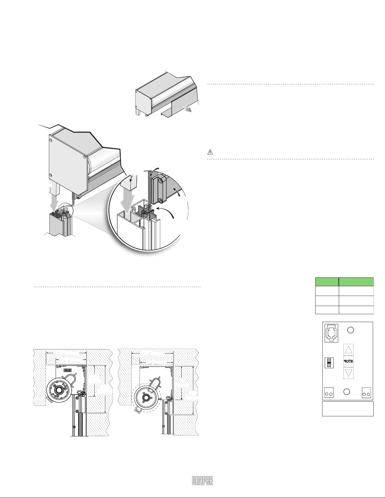
Mounting Headbox - Zip 127 Angled Headbox
The LightBloc Zip 127 Angled Headbox can be mounted permanently to the
wall or ceiling (See Mounting Headbox - Permanently to Ceiling or Wall on
page 1); or the Headbox can rest atop the Side Channels and is held in place
there by two mounting studs coming down from the endcaps.
PLEASE NOTE:
Steps 1-5of the Mounting Side Channels
section must be completed before mounting
the Zip 127 Angled Headbox. It is critical that
the full length of each Side Channel
is secured to the mounting surface.
1Remove screws from bottom of Headbox,
remove Fascia and set aside. (See Fig. 11).
2 Insert "Zipper" on one side of
the Hem Bar into the fabric
retainer in the Side Channels
(See Fig. 12).
3Insert "Zippers" on the side of the Hem Bar into the fabric retainers in the
Side Channels (See Fig. 12).
4Insert Headbox mounting stud into Side Channel (See Fig. 12).
5Return Fabric Retainers to Side Channels and re-attach Covers.
Pocket Installation
The LightBloc Zip can also be installed in a pocket in the ceiling. You must
provide adequate clearance for removal of the Roller Assembly during
installation and maintenance.
The minimum depth of the ceiling pocket for the LightBloc Zip 92 is 4¾"
(120mm), and for the LightBloc Zip 127 is 6¼" (158mm). See Fig 13 below.
Page 3 of 6
REMOVE
Complete Electrical Connection
The LightBloc Zip operates on 110-120V, 60 Hz. current. Shade is shipped
with internal wiring complete and control switch (es) fully boxed, and supplied
with a 6' cable lead (standard). Longer lead can be substituted by removing
two screws in motor end of roller, removing lead, plugging new lead in, and
replacing screws. Wire to connect shade to switch (es) and switch (es) to
power supply should be furnished by installer. Connections should be made
in accordance with attached wiring diagram, and wiring should comply with
national and local electrical codes.
DO NOT wire motors in parallel without written permission from Draper.
All operating switches should be “off” before power is connected.
Alternate Mounting for Jamb Recessed
Installations (Zip 127 Angled Only)
If the system is installed in a recess, it is unlikely that there will be sufficient
space above the side channels to allow the Headbox to be mounted onto them.
In these instances follow the steps for preparing the system (See Mount-
ing Headbox - Zip 127 Angled Headbox). Then mount the Headbox onto
the side channels and present the entire system into the opening. Hold the
system in position and use appropriate screws to fix the side channels in
place. Apart from this, the other steps should be followed as described.
Limit Switch Adjustments—Standard Motor
CAUTION: Be sure all switches are in “off” position before adjusting limit switches.
Always be prepared to shut off manually when new adjustment is being tested.
Do not allow the shade roller to become exposed by running the shade
fabric too far down. Shade may be severely damaged if allowed to run too far up
or down. Each shade’s limit switch must be set if using group control system.
1Fully depress both limit switch push buttons, then operate wall switch to make
sure system works properly.
2Raise shade to desired “up” stop position.
3Set upper limit by depressing and releasing the proper (back) push button.
4Lower shade to desired “down” stop position.
5Set lower limit by depressing and releasing the proper (front) push button.
Limit Switch Adjustments—RTS Motors
For instructions on setting limits on these motors, consult Draper's Motorized
Shade Handbook, available in the motorized shades section of www.draperinc.com.
Limit Adjustments (ILT Motors)
1Connect the ILT switch to the motor via the terminal blocks, or via the modular
port using four conductor modular cable. When using modular cable, the cable
connectors MUST NOT be crimped in
reverse, as with standard telephone cable.
2Set the slide switch to the lower
position. Press and hold the DOWN
button on the switch to move the
viewing surface to the desired lower
limit. If the shade moves in the opposite
direction, release the DOWN button
and press and hold down the STOP
button for four seconds. This will
reverse the operation of the
UP and DOWN switches.
3Move slider switch into center position.
Wait a couple of seconds.
Please Note: If you move the slider switch
from down to up in one motion it sets the two
limits in the same position.
4Set the slide switch to the higher
position. Move the shade to the desired
upper limit by pressing and holding the
UP button on the wall switch.
5Return the slide switch to the center
position to return to normal operation.
6To set the shade to an intermediate
position, move the shade to the desired
position and press the STOP button. Press and hold the STOP button for at
least three seconds to record the postion.
Please Note: Pressing and releasing the UP button on the switch will move the shade to its
upper limit. Pressing and releasing the DOWN button will move the shade to its lower limit.
While the motor is in motion, pressing the STOP button for less than two seconds will stop the
shade at its present position. Once the motor is stopped, pressing the STOP button will move
the shade to its intermediate position.
Pressing and holding the STOP button, when the motor is at rest or in motion, for at least
three seconds will record a new position.
Figure (11)
FABRIC
RETAINER
STRIP
HEADBOX
MOUNTING
STUD
ZIPPER
HEMBAR
HEADBOX
MOUNTING
STUD
Figure (12)
WALL
WALL
3 5/8” (92mm)
4 ¾” (120mm)
3 5/8”
(92mm)
5 7/8”
(148mm)
5” (127mm)
6¼” (158mm)
5”
(127mm)
7¼”
(183mm)
FlexShade Zip 127 FlexShade Zip 92
Figure
WALL
WALL
3
5
/
8
”
(92mm)
4 ¾”
(120mm)
3
5
/
8
”
(92mm)
5
7
/
8
”
(148mm)
5” (
127mm)
6¼” (
158mm)
5”
(
127mm)
7¼”
(
183mm)
FlexShade Zip 127 FlexShade Zip 92
Figure (11)
POSITION FUNCTION
DOWN
UP
CENTER
SetLOWER limit
Set UPPER limit
Normal Operation
To Motor
with
Built-In
Low Voltage
Slide
Switch
Back View of Wall Switch
U
p
D
o
w
n
C
o
m
m
o
n
+
5V
DC
To Motor
with
Built-In
Low Voltage
Please Note: 5V DC must be
connected to be able to set
limits using the wall switch.
POSITION FUNCTION
DOWN
UP
CENTER
SetLOWER limit
Set UPPER limit
Normal Operation
To Motor
with
Built-In
Low Voltage
Slide
Switch
U
p
D
o
w
n
C
o
m
m
o
n
+
5V
DC
To Motor
with
Built-In
Low Voltage


