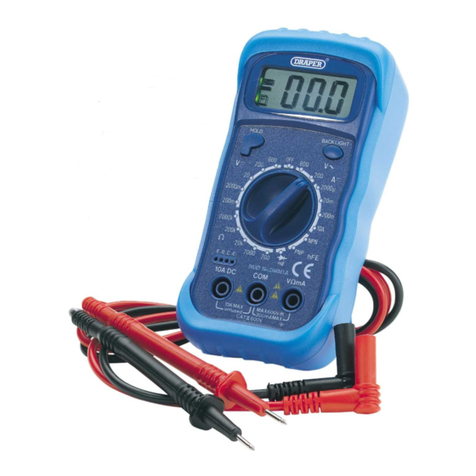
Draper DMM11 User manual

AUTORANGING
MULTIMETER
■STOCK No.59315 ■PART No.DMM11
12/99
• INSTRUCTIONS •
IMPORTANT: PLEASE READ THESE INSTRUCTIONS CAREFULLY TO ENSURE
THE SAFE AND EFFECTIVE USE OF THIS TOOL.

INTRODUCTION
FEATURES
Autoranging Multimeter
This multimeter is ideal for general electrical and automotive use.
- 1-
SPECIFICATION
■13 position rotary function and range selector.
■Recessed input terminals for added safety.
■Measures A.C./D.C. voltage, A.C./D.C. amps, frequency, resistance and capacitance.
■200mA fuse protection.
■Audible continuity buzzer.
■Diode test facility.
■Hi-impact rubber case with integral stands.
■Supplied with test leads, probes and battery.
WARNING:
To avoid electric shock remove test leads before opening cover. To prevent risk of fire use
only the correct fuse as shown on the rear cover of the meter. (Fuse is bypassed on 20A
setting, ensure you refer to point 5 and 6 on page 3).
■D.C.Voltage: 3.26V, 32.6V, 326V (accuracy +/- 0.3% of rdg. +/- 2 digits). 326mV, 1000V,
(accuracy +/- 0.5% of rdg. +/- 2 digits).
■A.C.Voltage: 3.26V, 32.6V, 326V, 750V (accuracy +/- 0.8% of rdg. +/- 3 digits).
■D.C. Amps: 326µA, 3260µA, 32.6mA, 326mA, (accuracy +/- 1.3% of rdg. +/- 3 digits). 10A,
(accuracy +/- 2.0% of rdg. +/- 5 digits).
■A.C. Amps: 326µA, 3260µA, 32.6mA, 326mA, (accuracy +/- 1.5% of rdg. +/- 5 digits).
■Resistance: 326Ω, (accuracy +/- 0.8% of rdg. +/- 3 digits). 3.26KΩ, 32.6KΩ, 326KΩ,
3.26MΩ, (accuracy +/- 0.8% of rdg. +/- 1 digit). 32.6MΩ, (accuracy +/- 1.2% of rdg. +/- 2
digits).
■Frequency: 32.6KHz (accuracy +/- 1.2% of rdg. +/- 3 digits). 200KHz (accuracy +/- 2.5%
of rdg. +/- 3 digits).
■Capacitance (manual ranging): 326nF, 32.6µf, (accuracy +/- 3.0% of rdg. +/- 5 digits).

- 2 -
MAINTENANCE
The fuse rarely needs replacing, and almost always a blown fuse is the result of operator
error. (see warning on front page).
If the meter battery is in need of replacement,‘ ’ will appear on the display.
ACCESSORIES
PART No: YDMM7
STOCK No: 53549
DESCRIPTION: Multimeter Crocodile clip and Probe Set.
PART No: YDMM7
STOCK No: 53548
DESCRIPTION: Spare Probe Set.
Fig 1.

- 3-
KNOW YOUR MULTIMETER
✖✌
✛✌
✕✌
✘✌
✗✌
✚✌
✜✌
✙✌
✕✔✌
✢✌

- 4-
KNOW YOUR MULTIMETER
1. Autoranging Function Switch
This switch is used to select the function and desired range.
2. Display
LCD display unit.
3. ‘COM’ Jack Socket
Plug in the black (negative) test lead.
4. ‘V/Ω/F (voltage/resistance/frequency) Jack Socket (max 200mA)
Plug in the red (positive) test lead for all voltage, resistance and amperage (max 200mA)
measurements.
5. ‘10A’ Jack socket (max 10A)
Plug in the red (positive) test lead for measuring amperage to a minimum of 200mA, to a
maximum of 10A.
6. ‘mA/Cx’ (amps/capacitance) Jack Socket (max 300mA)
Plug in the red (positive) test lead for measuring all amperage and capacitance values up
to a maximum of 300A.
7. Transistor Test Socket
Suitable for both NPN and PNP transistors.
8. A.C./D.C. Amps or Selecting Button
Suitable for diode or continuity testing.
9. Range Control Button
For selecting measurement reading ranges on LCD display unit.
10.Data Hold Button
For storing measurement readings in a memory system. To clear or cancel the reading
automatically, turn the autoranging function switch to another function/setting.
OTHER METER MARKINGS/READINGS
µA,mA,A
mV, V
Ω,KΩ,MΩ
ACV
DCV
DCA
OHM
Diode or continuity test modes
have been selected.
Indicates that the meter battery
voltage has dropped
excessively.
Units for current
measurements.
Units for voltage
measurements.
Units for resistance
measurements.
Indicates low battery.
Caution (see note 5 above and
warning on page 1).
Caution, risk of electric shock.
AC Voltage ranges.
DC Voltage ranges.
DC Current ranges.
Resistance ranges.
OL Indicates overload.

- 5 -
OPERATION
WARNINGS:
Before you use the instrument, inspect the test leads, connectors and probes for damage e.g.
cracks or breaks in the insulation. Replace any defective leads before use. If the voltage to be
measured is not known, set the selector switch to the highest range and reduce until a satisfactory
reading is obtained.
DC Voltage Measurement
1. Connect the red test lead to the ‘V/Ω/F’ jack socket and the black lead to the ‘COM’
jack socket.
2. Set the selector switch to the desired D.C.V. range (V ... ).
3. Connect the test leads to the circuit to be measured.
4. Turn on the power to the circuit to be measured, the value should appear on the digital display
along with the voltage polarity (if reversed only).
AC Voltage Measurement
1. Connect the red test lead to the ‘V/Ω/mA’ jack socket and the black lead to the ‘COM’
jack socket.
2. Set the selector switch to the desired A.C.V. range (V~).
3. Connect the test leads to the circuit to be measured.
4. Turn on the power to the circuit to be measured. The voltage value will appear on the
digital display.
Current Measurement
1. Connect the red test lead to the ‘mA’ or ‘A’ jack socket and the black lead to the ‘COM
jack socket. (For measurements between 200mA and 10A connect the red test lead to the
‘A’ socket. (Max. 20A).
2. Set the selector switch to the desired A.C./D.C. range (µA, mA or A) and push the ‘ .../~’
button.
3. Open the circuit to be measured and connect the test leads IN SERIES with the load
in which current is to be measured. (See Fig. 1).
4. Turn on the power to the circuit to be measured the ‘AMPERAGE’ value should appear on the
digital display.
Resistance Measurement
1. Connect the red test lead to the ‘V/Ω/F’ jack socket and the black lead to the ‘COM’
jack socket.
2. Set the selector switch to the OHM position (Ω).
3. WARNING: If the resistance to be measured is part of a circuit, turn off the power and
discharge all capacitors before measurement. If the reading is less than 200MΩ, the
display will show 1MΩ, this figure should be subtracted from measurement results.
4. Connect the test leads to the circuit to be measured.
5. The resistance value should now appear on the digital display.
Diode Measurement
1. Connect the red test lead to the ‘V/Ω/F’ jack socket and the black lead to the ‘COM’ jack
socket.
2. Set the selector switch to the position.
3. Connect the red test lead to the anode of the diode to be measured and the black test
lead to the cathode.
4. The forward voltage drop in mV will be displayed. If the diode is reversed, the figure ‘1’
should show on the display.

- 6-
Transistor hFE Test
1. Set the selector switch to the hFE position.
2. Determine whether the transistor is NPN or PNP.
3. Locate the emitter (E), base (B) or (C)and collect legs into the correct holes in the socket on the
front panel.
4. The display will read the approximate hFE value at the test condition of base current
10µA VCE 3.2V.
Frequency Measurement
1. Connect the red test lead to the ‘V/Ω/F’ jack socket and the black lead to the ‘COM’
jack socket.
2. Set the selector switch to the Hz position and the range button to 20KHz.
3. Connect the test leads to the circuit/source to be measured.
4. The frequency value should now be displayed on the digital display.
Note: Readings can be taken from input voltages above 10Vms, but the accuracy is not
guaranteed. In noisy environments, it is recommended that shielded cables are used for
measuring small signals.
Capacitance Measurement
1. Set the selector switch to the desired setting within the ‘F’ range (nF or µF).
NOTE: The range control mode in capacitance measurement is manual ranging and only two
ranges (326nF, 32.6µF) are provided. If the range control button is used in this function
measurement, decimal points may appear in wrong positions.
2. Before testing the capacitor be sure that the capacitor has been fully discharged.
3. When measuring capacitors with short leads, a testing adaptor has been provided. Insert
the adaptor into the testing sockets, but remember to remove it before selecting another
function, to avoid the risk of an electric shock.
4. Once the capacitor has been placed into the testing sockets, the capacitance value will be
displayed on the digital display.
Continuity Diode Test
1. Connect the red test lead to the V/Ω/F jack socket and the black lead to the ‘COM’
jack socket.
2. Set the selector switch to the position.
3. Connect the test leads to the circuit/source to be tested.
4. If continuity exists (i.e. resistance is less than 50Ω) the audible buzzer will sound.
Autoranging Feature
1. Ranges for A.C./D.C. voltage, A.C./D.C. amps (µA and mA only), resistance and frequency can
be measured manually or automatically by following this sequence:
a. Set the selector function switch to the required function.
b. Press the red range button until ‘R-H’ is displayed in the top left hand corner of the LCD screen.
c. To change the range, press the red range button until the desired measurement range is
displayed.
d. To turn the autoranging feature to manual, depress and hold the red range button down for
more than three seconds.

DRAPER TOOLS LIMITED,
Hursley Road, Chandler's Ford,
Eastleigh, Hants. SO53 1YF. England.
Tel: (023) 8026 6355.
Fax: (023) 8026 0784.
©Published by Draper Tools Ltd.
No part of this publication may be reproduced,
stored in a retrieval system or transmitted in
any form or by any means, electronic, mechanical
photocopying, recording or otherwise without prior
permission in writing from Draper Tools Ltd.
YOUR DRAPER STOCKIST
Table of contents
Other Draper Multimeter manuals
Draper
Draper DMM1A User manual
Draper
Draper AMM1 User manual
Draper
Draper 300 Series User manual
Draper
Draper 37317 User manual
Draper
Draper DMM6B User manual
Draper
Draper DMM11B Firmware update
Draper
Draper A.C. User manual

Draper
Draper 50024 User manual
Draper
Draper DMM17 Firmware update
Draper
Draper 200 Series User manual
