• Nyomja meg a„RANGE”gombot az
automatikus/kézi méréshatár-váltás
kiválasztásához.
Figyelmeztetés: Biztosítsa a mérendő áramkör
feszültségmentességét!
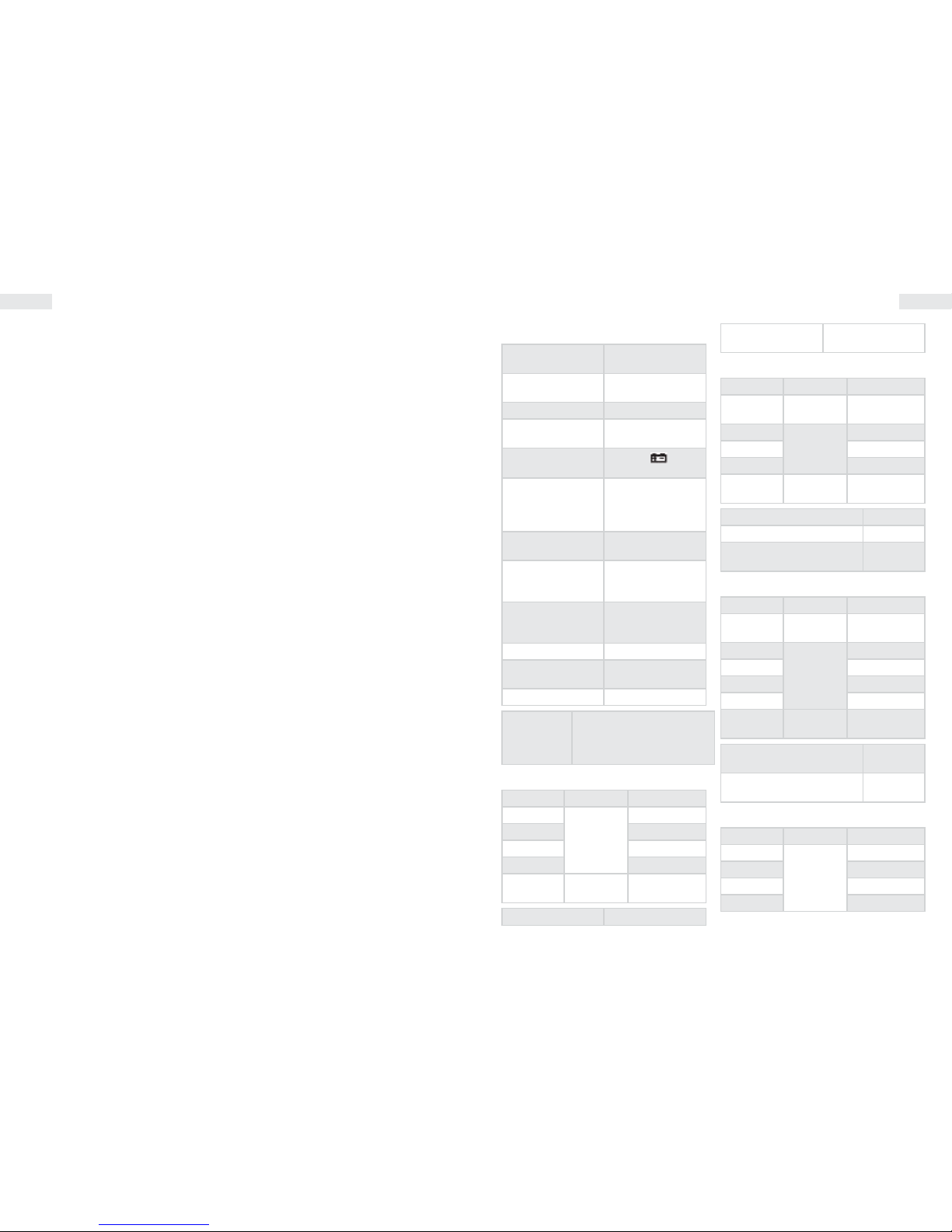
Kapacitásmérés
• Állítsa a funkcióválasztó kapcsolót a -ll- állásba.
• Nyomja meg egyszer a„REL” feliratú gombot a
kijelző nullázásához.
• Csatlakoztassa a fekete mérőzsínórt a„COM”, a
pirosat a„V/Ω”aljzatba. Éríntse a tapogatókat a
kondenzátor kivezetéseihez, ügyelve a helyes
polarításra.
Megjegyzés:
A kapacitásmérés automata méréshatár-váltós.
Mértékegység: 1 nF=10-3 μF vagy 1000 pF.
Ne csatlakoztasson külső feszültséget vagy feltöltött
kondenzátort (különösen nagy kapacitásúakat) az
aljzatba. Mérés előtt a kondenzátorokat süsse ki. Az
elektrolit kondenzátorokat mérés előtt többször süsse ki!
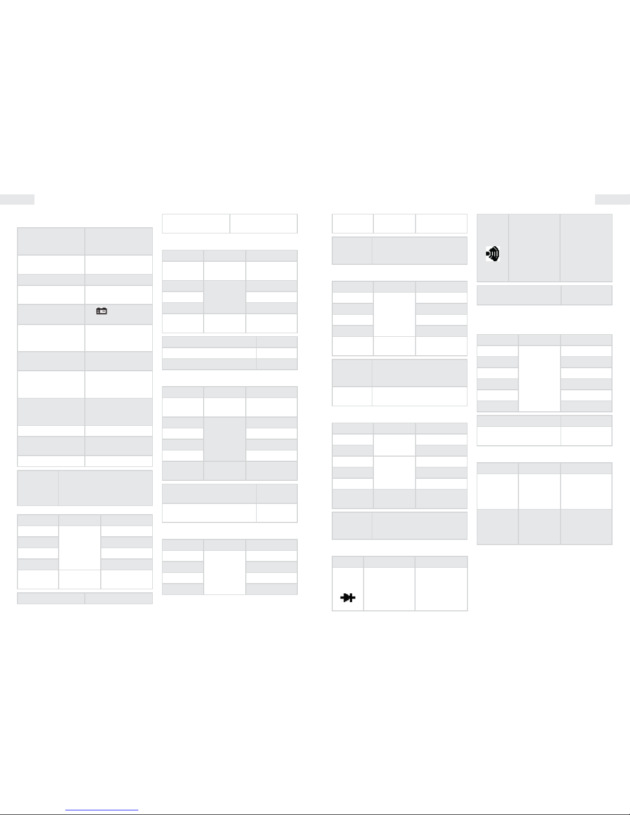
Dióda és folytonosság teszt
• Csatlakoztassa a fekete műszerzsinórt a„COM”,
a pirosat a„VΩHz” aljzatba. (Megjegyzés: a
piros tapogató polaritása: +)
• Állítsa a funkció kapcsolót a állásba.
• Érintse a tapogatókat a dióda kivezetéseihez. A
kijelzőn a dióda nyitófeszültsége látható.
• Érintse a tapogatókat az áramkör két pontjára.
Sípoló hang jelez, ha az ellenállás kisebb 50
Ω-nál.
Tranzisztor hFE teszt
• Állítsa a funkciókapcsolót a hFE állásba
• Határozza meg, hogy a tranzisztor NPN vagy
PNP, és helyezze az alkatrészt a lábkiosztásának
megfelelő csatlakozóba (ezen csatlakozó aljzat
a műszer tartozéka és a mA + COM bemeneti
aljzatokba csatlakozik).
• A kijelzőről a tranzisztor áramerősítési
tényezője olvasható le.
I = 15 μA, V = 1,5 VBC
Frekvenciamérés
• Csatlakoztassa a műszerzsinórt vagy az
árnyékolt kábelt a„COM”és a„VΩHz”
aljzatokba.
• Állítsa a funkciókapcsolót„30MHz”állásba és
érintse a tapogatókat a jelforráshoz.
Megjegyzés:
• Ne mérjen 250 V(RMS)nál nagyobb feszültségen
frekvenciát.
• Zajos környezetben célszerű árnyékolt kábel használni
kis jelek mérésénél.
• Nagyfeszültségű méréskor kerülje az áramkör érintését.
• Frekvenciamérésnél a méréshatár-váltás mindig
automatikus.
Kitöltési tényező mérés
Állítsa a funkciókapcsolót 30MHz állásba, majd
egyszer nyomja meg a Hz/DUTY gombot, a
kitöltési tényező méréséhez.
Adatrögzítés
A ’HOLD’ gomb megnyomásának hatására a
kijelzőn az éppen akkor mért érték marad, addig
amíg újra meg
nem nyomja ezt a gombot.
Figyelmeztetés
• Feszültségmérésnél biztosítsa, hogy a vezetékek
ne csatlakozzanak árammérő aljzathoz és a
funkciókapcsoló ne legyen ellenállás vagy dióda
ellenőrző állásban.Mindig ellenőrizze, hogy a mérendő
mennyiségnek megfelelő aljzatba csatlakoztatta-e a
vezetéket.
• Legyen körültekintő 50V-nál nagyobb feszültség
mérésekor, különösen erősáramú berendezéseknél.
• Kerülje az„élő” áramkörökhöz való csatlakozást.
• Árammérésnél az áramkört feszültségmentesítse,
mielőtt csatlakoztatná hozzá a multimétert.
• Ellenállásmérés és dióda tesztelés előtt gondoskodjon
az áramkör feszültségmentesítéséről a mérés idejére.
• Mindig a mérésnek megfelelő funkciót és méréshatárt
válassza. Ha kétséges a mérendő mennyiség
nagyságrendje, válassza a legmagasabb méréshatárt és
onnan haladjon visszafelé.
• Győződjön meg a műszerzsinór hibátlan állapotáról, a
szigetelés sértetlenségéről.
• Legyen óvatos, ne lépje túl a leírásban megadott
túlterheléshatárokat.
• Biztosítékot csak azonos típusúra és értékűre cseréljen.
• Biztosíték- vagy elemcserénél a műszer tokjának
kinyitása előtt kapcsoljon le minden külső áramkört és
állítsa a funkciókapcsolót OFF állásba.
Ha a szondát nem csatlakoztatjuk az aljzatba, akkor a
műszer a környezete hőmérsékletét mutatja.
Ne kapcsoljon a bemenetekre külső feszültséget, ha a
műszer hőmérsékletmérő állásban van.
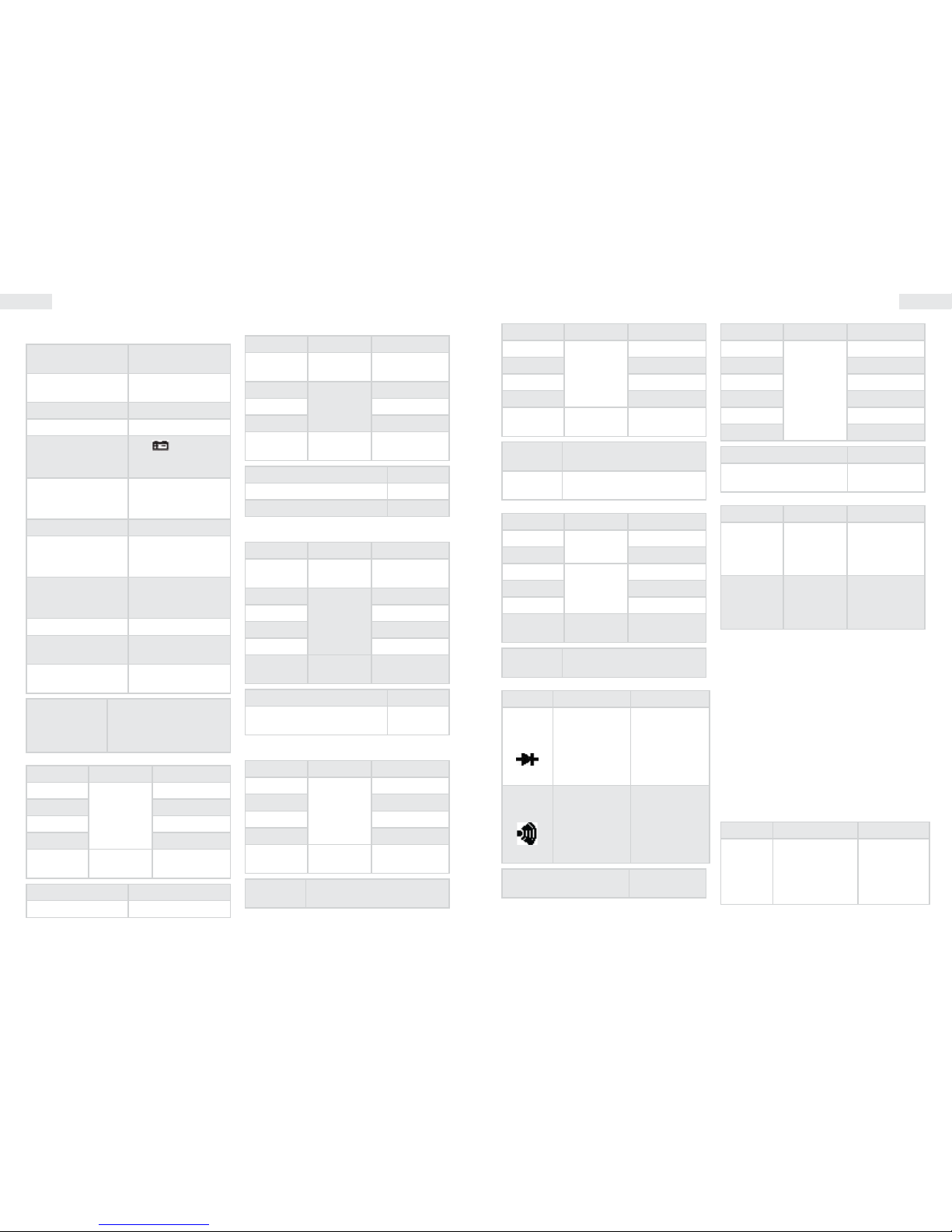
Tranzisztor hFE teszt
Funkció Leírás Teszt állapot
hFE
A tranzisztor
áramerősítési
tényezőjét méri
(0-1000)
(Minden típus)
Bázisáram kb.
10 μA
VCE kb. 3 V
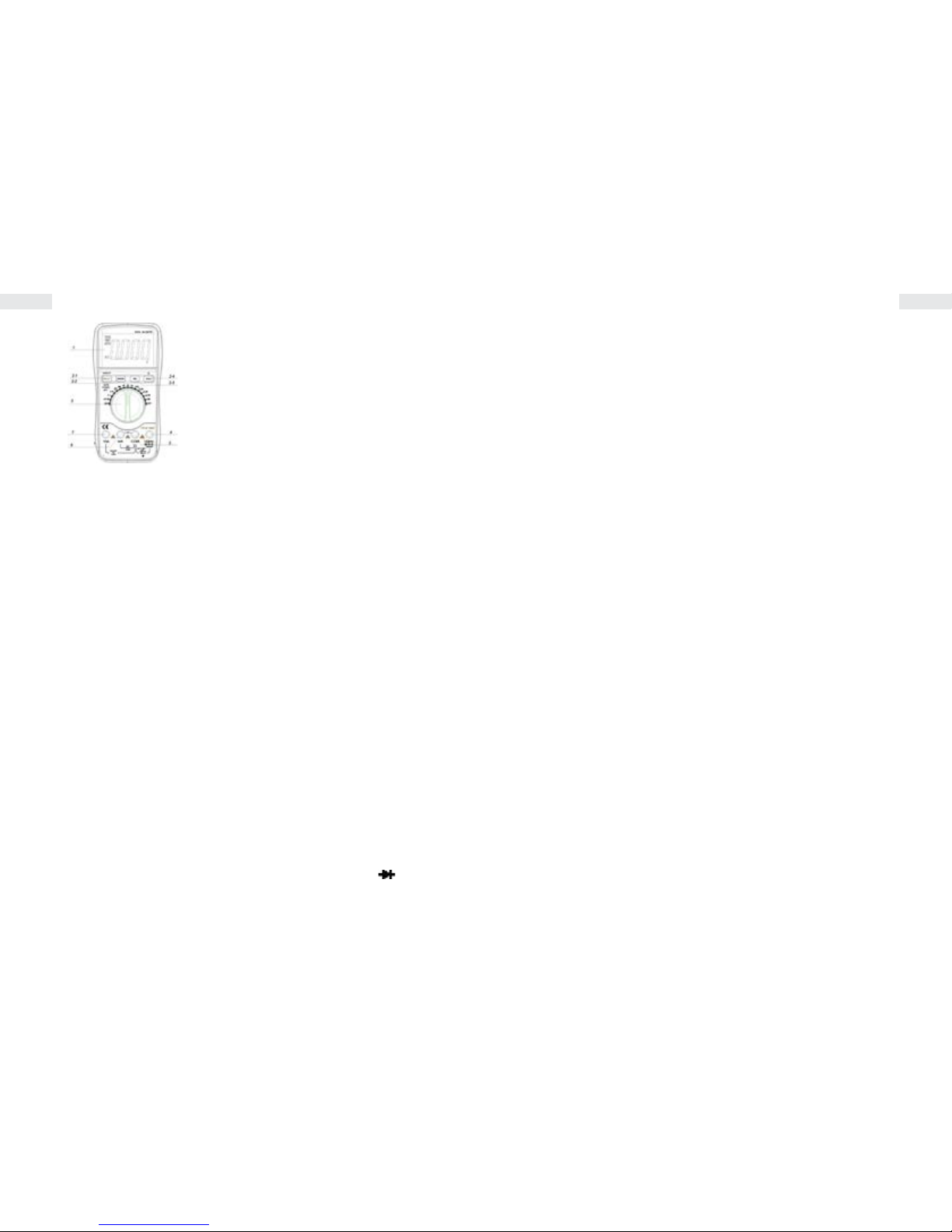
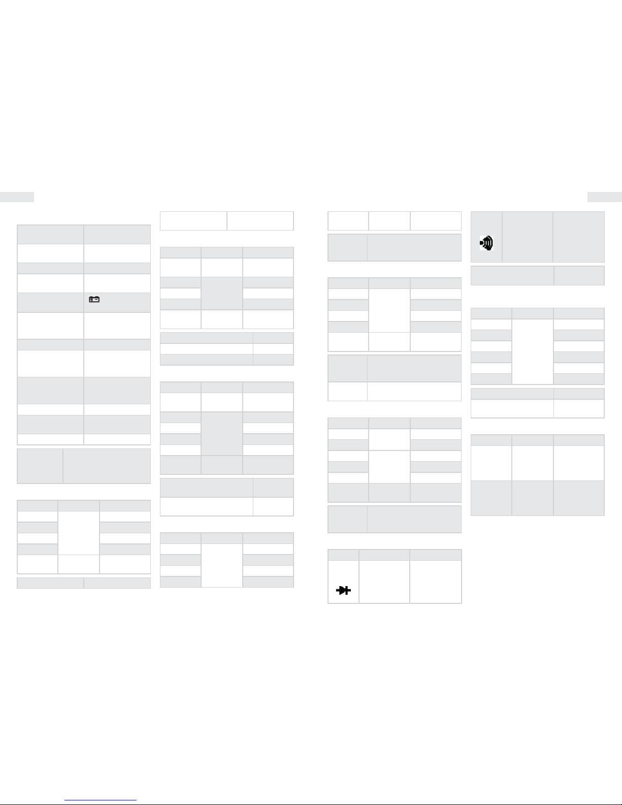
1.LCD: kijelzi a mért értéket és a mértékegységet
2.Funkció gombok:
2-1.“select” key : select DC/AC ,frequency and
Duty cycle . Hz/DUTY Key: when measure
DCA,press the key to switch ACA.When measure
frequency ,press the key to switch frequency/
duty cycle(1~99%).
2-2. RANGE Key: select working mode
of automatic measurement and manual
measurement.the default mode is automatic
measurement and“AUTO” is displayed ,press
the key turn into manual measurement ,press
the key for 2 sec. will return to automatic
measurement condition.
2-3. press the key at voltage ,current and
capacitance range, reading is reset and enter
into relative value measurement ,LCD displaying
“REL” symbol,press it again will exit the function.
2-4.HOLD Key:Press the key ,the present value is
held on LCD and display “HOLD”,press it again
will exit the function ; Press the key for 2 sec. will
turn to the backlight.
3.Rotary Switch: selecting measuring function
and range.
4.Voltage, Resistance, Frequency socket.
5.GND.
6.COM for measuring current less than 400mA.
7.COM for measuring current 10A.
• Az aljzatok melletti jelzések gyelmeztetnek,
hogy a bemenő feszültség vagy áram ne
haladja meg a jelzett értéket. Így elkerülheti a
belső áramkörök sérülését.
• A funkcióválasztó kapcsolót a mérés előtt
állítsa a megfelelő állásba (funkcióhoz)
• Ha a mérendő mennyiség nagyságrendjét
nem ismeri, állítsa a kapcsolót a legmagasabb
méréshatárra és onnan haladjon visszafelé,
amíg a megfelelő értéket eléri.
DC és AC feszültség mérése
• Csatlakoztassa a fekete csatlakozót a„COM”, a
piros csatlakozót a„VΩHz” aljzatba.
• Alapállapotban az automata méréshatár-váltás
aktív, amit a kijelzőn az„AUTO”felirat jelez. A
RANGE gomb megnyomásával kézzel állíthatja
a méréshatárt: 400 mV/4 V/40 V/400 V/1000 V.
• Állítsa a funkcióválasztó kapcsolót a megfelelő
V pozícióba és csatlakoztassa a tapogatókat
párhuzamosan a feszültségforrással a mérés
idejére.
DC és AC áram mérése
• Csatlakoztassa a fekete vezetéket a„COM”, a
piros vezetéket pedig a„mA”vagy„10A”jelzésű
aljzatba, 400 mA-es illetve 10A-es méréshez.
• Állítsa a funkció kapcsolót a megfelelő
méréshatárhoz.
• Csatlakoztassa a tapogatókat sorosan az
áramforrással a méréshez.
• 400 mA és 10 A közötti áram méréséhez az
előző pontokat kövesse, de a piros mérőzsinórt
a„10A” jelzésű aljzatba csatlakoztassa.
Ellenállásmérés
• Csatlakoztassa a fekete vezetéket a„COM”, a
piros vezetéket pedig a„V/ΩHz” aljzatba.
• Állítsa a funkció kapcsolót a kívánt ellenállás
méréshatárra.
• Csatlakoztassa az érintkezőket a mérendő
áramkörrel párhuzamosan.