✷✵✌
INTRODUCTIE
DIGITALE MULTIMETER:
Deze lichtgewicht multimeter is ideaal voor algemeen elektrisch en technisch
gebruik.
■Keuzeschakelaar met 9 posities.
■13 functies/bereiken.
■Meet gelijkstroom en wisselstroomspanning, gelijkstroom ampère en weerstand.
■Diodetest faciliteit.
■Compleet met testdraden en batterijen.
■Gelijkstroomspanning - 2,000mV, 20V, 200V, 450V (nauwkeurigheid ± 0.5%
maximum).
■Wisselstroomspanning - 200V, 450V (nauwkeurigheid ± 2% maximum).
■Gelijkstroom ampère - 200mA (nauwkeurigheid ± 2% maximum).
■Weerstand - 2000, 20K. 200K, 2m Ohm. (nauwkeurigheid ± 2% maximum).
■Diodetest - stroom 1.6A maximum
- spanning 3.2V maximum
■Batterijtype - R23: 12Vxl
■Zekering beschermd 0.2 ampère 250V snel
■Gewicht - 72g (inclusief batterij)
VOORZICHTIG
Dit instrument heeft geen componenten waarvoor onderhoud nodig is. Het vervangen van de zek-
ering mag alleen worden uitgevoerd door een vakkundig persoon.
WAARSCHUWING:
Om brandgevaar te vermijden dient de correcte zekering te worden gebruikt (zie hoger).
KENMERKEN
SPECIFICATIE
METERMARKERINGEN/AFLEZINGEN
Diode testmodus.
Geeft aan dat de batterijspanning
van de meter overmatig is gedaald.
Eenheid voor stroommeting.
Eenheid voor weerstandmeting.
Voorzichtig.
“BAT”
m
K,m Ω
CONFORMVERKLARING
WAARSCHUWINGEN:
Alvorens dit instrument te gebruiken dient u de testdraden en sondes op
eventuele beschadiging te inspecteren, bijv. barsten of contactverbrekingen in de
isolatie.
Indien de te meten spanning niet bekend is moet de keuzeschakelaar op het hoog-
ste bereik worden geplaatst en langzaam te worden verlaagd tot een passende
aflezing wordt verkregen.
Gelijkstroom spanningmeting
1. Plaats de keuzeschakelaar op het gewenste DVC bereik.
2. Activeer het te meten circuit.
3. Verbind de testdraden voor het te meten circuit. De spanningwaarde zal worden
getoond op de digitale display, samen met de polariteit (alleen indien omge-
keerd).
Wisselstroom spanningmeting
1. Draai de keuzeschakelaar op het gewenste AVC bereik.
2. Activeer het te meten circuit.
3. Verbind de testdraden voor het te meten circuit. De spanningwaarde zal worden
getoond op de digitale display.
Gelijkstroommeting
1. Plaats de keuzeschakelaar op het gewenste AVC bereik.
2. Open het te meten circuit en verbind de testdraden in serie met de belasting
waarin de stroom moet worden gemeten.
3. Activeer het te meten circuit, de ‘huidige’ waarde zal op de digitale display wor-
den getoond.
Weerstandmeting
1. Plaats de keuzeschakelaar op het gewenste W bereik.
2. WAARSCHUWING: Als de te meten weerstand een onderdeel is van een circuit,
moet vóór het meten de stroom worden afgezet en moeten alle condensators
worden ontladen.
3. Verbind de testdraden met het te meten circuit.
4. De weerstandwaarde zal op de digitale display worden getoond.
Diodemeting
1. Plaats de keuzeschakelaar op .
2. Verbind de rode testdraad met de anode van de te meten diode en de zwarte
testdraad met de cathode.
3. De voorwaartse terugval in spanning in mV zal worden getoond. Als de diode
omgekeerd is zal het cijfer “1” op de display worden getoond.
Batterij
niet
weggooien,
maar
inleveren
als KCA.
DC Current Measurement
1. Set the range selector switch to the DCA range.
2. Open the circuit to be measured and connect the test leads in series with the
load in which current is to be measured.
3. Turn on the power to the circuit to be measured, the ‘current’ value will appear
on the digital display.
Resistance Measurement
1. Set the selector switch to the desired Ωrange.
2. WARNING: If the resistance to be measured is part of a circuit, turn off the
power and discharge all capacitors before measurement.
3. Connect the test leads to the circuit to be measured.
4. The resistance value should now appear on the digital display.
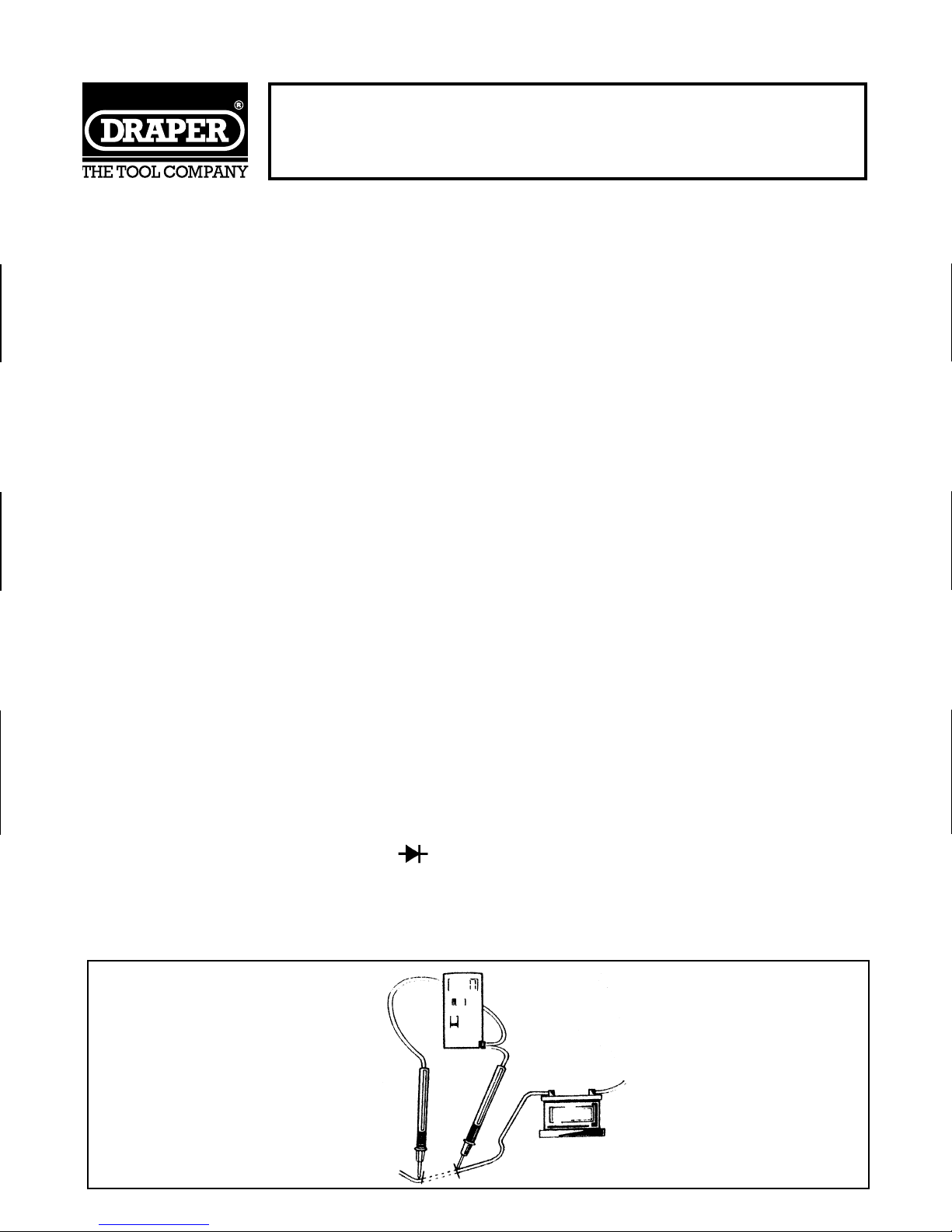
Diode Measurement
1. Set the selector switch to the position.
2. Connect the red test lead to the anode of the diode to be measured and the
black test lead to the cathode.
3. The forward voltage drop in mV will be displayed. If the diode is reversed, the
figure ‘l’ should be shown on the display.
Fig.1.
OPERATION CON...
Wij, Draper Tools Ltd, verklaren als enige
verantwoordelijken dat het product:
Voorraadnummer:- 50023 & 50024
Onderdeelnummer:- DMM4 & DMM5
Omschrijving:- Digitale multimeters
Waar deze verklaring betrekking op heeft, in
overeenstemming is met de volgende
richtlijnen:-
89/336/EEC
Oner verwijzing naar: EN 50081-1 & EN 50082-1
JOHN DRAPER
Managing Director
GEBRUIK
05/09/96
Afb. 1.
~
V
V
A
- wisselstroom spanning
bereik.
- gelijkstroommeting.
- weerstandbereik.
- gelijkstroom spanning
bereik