Draper stormforce 53084 User manual

130A ARC
WELDER
53084
These instructions accompanying the product are the original instructions. This document is part of the product,
keep it for the life of the product passing it on to any subsequent holder of the product. Read all these instructions
before assembling, operating or maintaining this product.
This manual has been compiled by Draper Tools describing the purpose for which the product has been designed,
and contains all the necessary information to ensure its correct and safe use. By following all the general safety
instructions contained in this manual, it will ensure both product and operator safety, together with longer life of the
product itself.
All photographs and drawings in this manual are supplied by Draper Tools to help illustrate the operation of the
product.
Whilst every effort has been made to ensure the accuracy of information contained in this manual, the Draper
Tools policy of continuous improvement determines the right to make modifications without prior warning.

1. INTRODUCTION
1.1 SCOPE
AC welding machine suited to light repair and fabrication
work.
This product is intended for domestic and infrequent
light trade use only. Any application other than that it
was intended for, is considered misuse.
This product is not a toy and must not be used by
children or any person with reduced physical, sensory or
mental capabilities or lack of experience and knowledge,
or people unfamiliar with these instructions.
Local regulations may restrict the age of the operator.
1.2 UNDERSTANDING THIS MANUALS
SAFETY CONTENT:
Warning! – Information that draws attention to the
risk of injury or death.
Caution! – Information that draws attention to the risk of
damage to the product or surroundings.
1.3 EXPLANATION OF SYMBOLS
Warning!
Read the instruction manual.
Warning!
Wear suitable welding eye/face protection.
Warning!
Wear ear defenders (During grinding
operations).
Warning!
Wear protective gloves.
Keep out of the reach of children.
Warning!
Danger of electric shock.
Danger of fire.
Danger of explosion.
Danger of fumes.
Danger of ultraviolet radiation.
Danger of burning splashes.
Fan cooled.
Power supply plug.
Input voltage.
Protection rating.
Thermal overload.
Electrode size.
Range.
Machine weight.
WEEE –
Waste Electrical & Electronic Equipment.
Do not dispose of Waste Electrical & Electronic
Equipment in with domestic rubbish.
Do not incinerate or throw
onto fire.
For indoor use only.
Do not expose to rain.
Class 1 appliance
(Must be earthed).
UK Conformity Assessed
–
2
–

–
3
–
European conformity.
2. SPECIFICATION
2.1 SPECIFICATION
Stock No. .............................................................. 53084
Part No. ............................................................ AW135T
Rated voltage .................................................. 230~50Hz
Effective input current............................................. 13.1A
Current range ..................................................... 50-130A
Coupling device.................................................. direct fit
Degree of protection.............................................. IP21S
Cooling ............................................................... Air (fan)
Insulation class............................................................. H
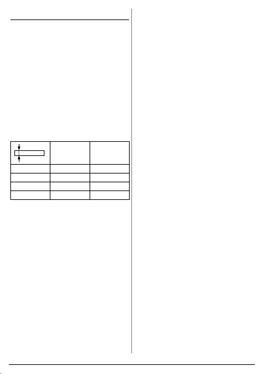
Duty cycle.......... 10% at 130A, 40% at 65A, 60% at 53A
Dimensions ..................................... 430 x 230 x 300mm
Weight (Gross/Net/machine only) ......... 12.5/11.5/11.0kg
3. HEALTH AND SAFETY
INFORMATION
3.1 General Arc-Welder Safety
Warnings
Warning! Read all safety warnings and all
instructions. Failure to follow the warnings and
instructions may result in electric shock, fire and/or
serious injury.
Save all warnings and instructions for future
reference.
MMA manual metal arc welding systems using coated
electrodes with limited service are referred to herein as
“welding machines”.
- Make sure that the welding machine is installed and
repaired only by qualified persons or experts in
compliance with the law and with the accident
prevention regulations.
- Make sure that the operator is trained in the use and
risks connected to the arc-welding processes and in
the necessary measures of protection and
emergency procedures.
- Detailed information can be found in the “Installation
and use of arc-welding equipment” brochure: IEC or
CLC/TS 62081.
- Make sure that the power socket to which the
welding machine is connected is protected by
suitable safety devices (fuses or automatic switch)
and that it is grounded.
- Make sure that the plug and power cable are in good
condition.
- Before plugging into the power socket, make sure
that the welding machine is switched off.
- Switch the welding machine off and pull the plug out
of the power socket as soon as you have finished
working.
- Switch the welding machine off and pull the plug out
of the power socket before connecting the welding
cables, installing the continuous wire, replacing any
parts in the torch or wire feeder, carrying out
maintenance operations, or moving it (use the
carrying handle on the welding machine.)
- Do not touch any electrified parts with bare skin or
wet clothing. Insulate yourself from the electrode, the
piece to be welded and any grounded accessible
metal parts. Use gloves, footwear and clothing
designed for this purpose and dry, non-flammable
insulating mats.
- Use the welding machine in a dry, ventilated space.
Do not expose the welding machine to rain or direct
sunshine.
- Use the welding machine only if all panels and
guards are in place and mounted correctly.
- Do not use the welding machine if it has been
dropped or struck, as it may not be safe. Have it
checked by a qualified person or an expert.
- Eliminate any welding fumes through appropriate
natural ventilation or using a smoke exhauster. A
systematic approach must be used to assess the
limits of exposure to welding fumes, depending on
their composition, concentration and the length of
exposure.
- Do not weld materials that have been cleaned with
chloride solvents or that have been near such
substances.
- Use a welding mask with adiactinic glass suited for
welding. Replace the mask if damaged; it may let in
radiation.
- Wear fireproof gloves, footwear and clothing to
protect the skin from the rays produced by the
welding arc and from sparks. Do not wear greasy
garments as a spark could set fire to them. Use
protective screens to protect people nearby.
- Do not allow bare skin to come into contact with hot
metal parts, such as the torch, electrode holder
grippers, electrode stubs, or freshly welded pieces.
- Metal-working gives off sparks and splinters. Wear
safety goggles with protective side eye guards.
- Welding sparks can trigger fires.
- Do not weld or cut anywhere near inflammable
materials, gasses or vapours.
- Do not weld or cut containers, cylinders, tanks or
piping unless a qualified technician or expert has
checked that it is possible to do so, or has made the
appropriate preparations.

–
4
–
- Remove the electrode from the electrode holder
gripper when you have completed the welding
operations. Make sure that no part of the electrode
holder gripper electric circuit touches the ground or
earth circuits; accidental contact could cause
overheating or trigger a fire.
- The magnetic fields deriving from the welding current
may interfere with electrical and electronic
equipment. People fitted with vital electrical devices
(pacemakers etc.) should consult a doctor prior to
coming into contact with welding equipment.
- This welding machine satisfies the requirements of
the technical product standard exclusively for
professional and industrial use. Compliance with
electromagnetic compatibility for domestic use is not
guaranteed.
- The welding machine is installed and used under
your own responsibility. In the event of
electromagnetic disturbance, this should be reduced
so that it does not cause problems. Ask a competent
expert for technical assistance if required.
Welding in conditions of risk
- If welding needs to be done in conditions of risk
(electric discharges, suffocation, the presence of
inflammable or explosive materials), make sure that
an authorised expert evaluates the conditions
beforehand. Make sure that trained people are
present who can intervene in the event of an
emergency. Use protective equipment described in
the IEC or CLC/TS 62081 technical specification.
- If you are required to work in a position raised above
ground level, always use a safety platform.
- If more than one welding machine has to be used on
the same piece, or in any case on pieces connected
electrically, the sum of the no-load voltages on the
electrode holders or on the torches may exceed the
safety levels. Make sure that an authorised expert
evaluates the conditions beforehand to see if such
risk exists and adopt the protective measures
described in 5.9 of the IEX or CLC/TS 62081
technical specification if required.
3.2 ADDITIONAL SAFETY
INSTRUCTIONS FOR ARC-WELDERS
- Do not use the welding machine for purposes other
than those described. For example to thaw frozen
water pipes.
- Place the welding machine on a flat stable surface.
and make sure that it cannot move. It must be
positioned in such a way as to allow it to be
controlled during use but without the risk of being
covered with welding sparks.
- Do not work with the welding machine hung from the
body, using straps or any other device.
- Do not lift the welding machine. No lifting devices are
fitted on the machine.
- Do not use cables with damaged insulation or loose
connections.
4. UNPACKING AND
CHECKING
4.1 PACKAGING
Carefully remove the product from the packaging and
examine it for any sign of damage. Check contents
against the parts shown in Fig A. If any part is damaged
or missing, please contact the Draper Help Line (see
back page). Do not attempt to use the product!
The packaging material should be retained during the
warranty period, in case the product needs to be
returned for repair.
Warning!
• Some of the packaging materials may be harmful to
children. Do not leave any of these materials in
reach of children.
• If any of the packaging is to be thrown away, make
sure they are disposed of correctly, according to local
regulations.

–
5
–
5. IDENTIFICATION – FIG.A
(1)
(2)
(3)
(5)
(8)
(9) (7)
(6)
(4)
FIG.A
(1) Carry handle
(2) Welding current indicator
(3) On/off switch
(4) Thermal overload indicator
(5) Current adjustment control
(6) Electrode holder
(7) Direct fit earth clamp
(8) Face mask
(9) Brush/hammer
6. ASSEMBLING THE
WELDER
Make sure the power supply information on the
machine’s rating plate is compatible with the power
supply you intend to connect it to.
A suitable plug must be fitted by a qualified
electrician.
This machines wiring has insulation stripped in
preparation for wiring a 16A plug (not supplied).
It is designed for connection to a 16amp power supply
rated at 230V AC.
Because it is constructed mostly of metal parts, it is a
Class 1 machine; meaning, it must have an earth
connection in the power supply. This is to prevent
electrocution in the event of a failure.
NOTE: Remove the plug from the socket before carrying
out adjustment, servicing or maintenance.
Check that the electrical supply delivers the voltage and
frequency corresponding to the welding machine and
that it is fitted with a delayed fuse suited to the maximum
delivered rated current.
NOTE: The welding machines are set to the highest
voltage at the factory.
6.1 PREPARING THE WELDING
CIRCUIT
Connect the ground “lead” to the piece to be welded.
Connect the welding electrode to the electrode holder.
When the machine is turned on and the electrode
touches, the workpiece, the electrical circuit is complete,
this will result in the welding arc being produced.

–
6
–
7. SETTING THE WELDER
Data plate on the welding machine.
(A) Constructor name and machine part No.
(B) Delivered alternate current frequency.
(C) Serial number
(D) European reference standard for the construction and safety of welding equipment.
(E) WELDING CIRCUIT PERFORMANCE
U0V Minimum and maximum open circuit voltage (open welding circuit).
ØDiameter of weldable electrodes.
I2A Value of the current needed to weld using different electrode diameters.
tw Welding time running from thermal cutout reset until the next tripping with the transformer at the
operating temperature.
tr Cooling time running from thermal cutout tripping until the next reset with the transformer at the
operating temperature.
A/V Conventional welding current (maximum) and corresponding normalised voltage.
(F) POWER SUPPLY DATA
U1 Input voltage (permitted tolerance: +/- 10%)
I1 eff Effective absorbed current.
I1 max Maximum absorbed current.
(G) Weight
(H) Safety symbols.
(I) Level of protection from solids and liquids.
(J) Input power required:
1” alternate single phase voltage, frequency
(K) Symbol indicating the possibility to use the welding machine in environments potentially subject to
electric discharges.
(L) Indicates the machine is an ARC/MMA process machine.
(M) Indicates this machine produces an AC welding current.
(A)
(M)
(L)
(K)
(J)
(B) (C)
(G)(H)(I)
(D)
(E)
(F)

8. SETTING THE WELDER
NOTE: Once you have put the welding machine into
operation, switch it on and carry out the required
adjustments.
8.1 ADJUSTING THE WELDING
CURRENT - FIG. 1
Select the welding current depending on the electrode,
the joint and the welding position.
Indicatively, the currents to be used with the different
electrode diameters are listed.
NOTE: Do not force the adjustment flywheel as this
could damage the welding machine. Check the
adjustment on the current adjustment indicator.
NOTE: To strike the welding arc with the coated
electrode, brush it onto the piece to be welded and as
soon as the arc is struck, hold it constantly at a distance
equal to the electrode diameter and at an angle of
approximately 20-30 degrees in the direction in which
you are welding.
mm Ø
mm AMP
1.0 1.6 30 - 50
2.0 - 3.5 2.0 50 - 75
2.5 - 3.0 2.5 75 - 105
3.0 - 4.0 3.2 105 - 140
1
FIG.
(N) Plate thickness
(O) RCD Diameter
(P) Welding amperage
8.2 THERMAL CUTOUT SIGNAL
The warning light switched on means that the thermal
protection is running.
If the welding time “tw” indicated in the data plate is
exceeded, a thermal cutout stops operation before the
welder is damaged. Wait for operation to be resumed
and, if possible, wait a few minutes more.
If the thermal cutout continues to cut in, the welding
machine is being pushed beyond its normal
performance levels.
8.3 RECOMMENDATIONS FOR USE
Only use an extension lead when absolutely necessary
and providing it has an equal or larger section to the
power cable and is fitted with a grounding conductor.
Do not block the welder air intakes. Do not store the
welder in containers or on shelving that does not
guarantee suitable ventilation.
Do not use the welder in any environment in the
presence of gas, vapours, conductive powders (e.g. iron
shavings), brackish air, caustic fumes or other agents
that could damage the metal parts and electrical
insulation.
NOTE: The electric parts of the welder have been
treated with protective resins. When used for the first
time, smoke may be noticed; this is caused by the resin
drying out completely. The smoke should only last for a
few minutes.
–
7
–

–
8
–
8. MAINTENANCE AND
TROUBLESHOOTING
8.2 MAINTENANCE
Regular inspection and cleaning reduces the necessity
for maintenance operations and will keep your tool in
good working condition.
The welder must be correctly ventilated during tool
operation. Avoid blocking the air inlets and vacuum the
ventilation slots regularly.
Do not use solvents or fuels to clean the product. When
not in use, store the product in a safe, dry place.
9. WARRANTY
9.1 WARRANTY
Draper tools have been carefully tested and inspected
before shipment and are guaranteed to be free from
defective materials and workmanship.
Should the tool develop a fault, please return the
complete tool to your nearest distributor or contact:
Draper Tools Limited, Chandler’s Ford, Eastleigh,
Hampshire, SO53 1YF. England.
Telephone Sales Desk: +44 (0)23 8049 4333 or:
Product Helpline +44 (0)23 8049 4344.
A proof of purchase must be provided.
If upon inspection it is found that the fault occurring is
due to defective materials or workmanship, repairs will
be carried out free of charge. This warranty period
covering labour is 12 months from the date of purchase
except where tools are hired out when the warranty
period is 90 days from the date of purchase. The
warranty is extended to 24 months for parts only. This
warranty doesnot apply to any consumable parts, any
type of battery or normal wear and tear, nor does it
cover any damage caused by misuse, careless or
unsafe handling, alterations, accidents, or repairs
attempted or made by any personnel other than the
authorised Draper warranty repair agent.
Note: If the tool is found not to be within the terms of
warranty, repairs and carriage charges will be quoted
and made accordingly.
This warranty applies in lieu of any other warranty
expressed or implied and variations of its terms are not
authorised.
Your Draper warranty is not effective unless you can
produce upon request a dated receipt or invoice to verify
your proof of purchase within the warranty period.
Please note that this warranty is an additional benefit
and does not affect your statutory rights.
Draper Tools Limited.
10. DISPOSAL
10.1 DISPOSAL
– At the end of the machine’s working life, or when it
can no longer be repaired, ensure that it is disposed
of according to national regulations.
– Contact your local authority for details of collection
schemes in your area.
In all circumstances:
• Do not dispose of power tools with
domestic waste.
• Do not incinerate.
• Do not dispose of WEEE* as unsorted
municipal waste.
* Waste Electrical & Electronic Equipment.
Table of contents
Other Draper Welding System manuals

Draper
Draper AW142AT User manual

Draper
Draper AW100A User manual

Draper
Draper INV106 User manual

Draper
Draper Expert 70052 User manual

Draper
Draper 71091 User manual

Draper
Draper MWD100AGL User manual

Draper
Draper acdc160p User manual

Draper
Draper MIG100GG User manual

Draper
Draper MW180AT User manual

Draper
Draper 70049 User manual

Draper
Draper 70047 User manual

Draper
Draper MW135AT User manual

Draper
Draper 71095 User manual

Draper
Draper MIG MWD100AT User manual

Draper
Draper AW164AT User manual

Draper
Draper MWD170AT User manual

Draper
Draper 70057 User manual

Draper
Draper AW140A User manual

Draper
Draper 71106 User manual

Draper
Draper MPW190 User manual