Truweld TW4300 User manual

Operations Manual
TW4300
Stud Welding System
Stud Welding
TRU-WELD

Table of Contents
Descripon Page
Warranty Informaon 1
Company Prole and Product Informaon 2
Safety Precauons - Symbols and Fumes 3
Safety Precauons - Electric Shock and Arc Rays 4
Safety Precauons - Welding Sparks and EMF’s 5
TW4300 Product Specicaons 6
TW4300 Setup and Installaon - Inial Steps 7
TW4300 Setup and Installaon - Power Diagrams 8
TW4300 Setup and Installaon - Primary Power 9
Stud Gun Setup - Inial Steps 10
Stud Gun Setup - Li Adjustment 11
Stud Gun Setup - Free Travel Adjustment and Weld Preparaon 12
Cable Connecon - Ground Cable and Weld Connecons 13
Machine Operaon - Powering On and Control Panel 14
Machine Operaon - Menu Selecon 15
Machine Operaon - Time and Current Sengs 16
Machine Operaon - Preset Menu 17
Machine Operaon - Stud Counters 18
Suggested Time and Current Sengs 19
Welding - Step by Step Process 20
Welding Hints and Suggesons 21
Weld Inspecon - Visual Inspecon 22
TW4300 Troubleshoong 23
TW4300 Troubleshoong 24

TRU-WELD EQUIPMENT LIMITED WARRANTY
All goods produced by TRU-WELD shall be warranted against defects including workmanship and components. No other
warranes whether expressed, verbal, or implied will apply. Warranes only apply to the original equipment purchaser.
Warranty claims will be limited to either repair or replacement of the defecve materials by TRU-WELD. At the opon of
TRU-WELD the locaon of where the warranty evaluaon and repairs are made will be determined. All warranty claim
items returned to TRU-WELD will be at the customer’s expense. At the opon of TRU-WELD the defect will either be
repaired or replaced. Noce must be provided to TRU-WELD of a warranty defect within 30 days that the defect or failure
is incurred. Warranes are not transferable.
This warranty does not apply for equipment which is used improperly in any fashion including but not exclusive to the
following:
• Equipment which has been modied
• Equipment which has not been installed properly
• Equipment which has been used for purposes other than which it had been designed
• Equipment which has not been properly maintained
• Equipment which was connued to be used aer a defect had been found
• Equipment which was damaged in any way
Truweld Equipment will never be liable for consequenal damages, loss, or expense occurring directly or indirectly from
the use of the equipment covered in this warranty.
All cables, cable sets and connectors are not covered under warranty
Two (2) year warranty period from date of purchase
● TWE250 Power Supply ● SC900 Power Supply ● SC2400 Power Supply ● TW5500 Power Supply
● TWE250CP Power Supply ● SC950 Power Supply ● SC2402 Power Supply ● TW5600 Power Supply
● TWE321 Power Supply ● SC1400Power Supply ● SC2420 Power Supply ● TW5700 Power Supply
● TWE375 Power Supply ● SC1450 Power Supply ● SC3400 Power Supply ● TW6800 Power Supply
● TW-i250 Power Supply ● SC1600 Power Supply ● SC3402 Power Supply ● TW6802 Power Supply
● TW-i250CP Power Supply ● SC1650 Power Supply ● SC3422 Power Supply ● TW6900 Power Supply
● TW-i321 Power Supply ● SC1900 Power Supply ● TW4300 Power Supply ● TW6902 Power Supply
● TW-i375 Power Supply ● SC1950 Power Supply ● TW4400 Power Supply ● TW6950 Power Supply
One (1) year warranty period from date of purchase
● TWESPC Power Supply ● TWP-2 Power Supply ● ACE-P100 Power Supply
Ninety (90) day warranty period from date of purchase
● TWEGP CD stud gun ● TWE17000 HD arc stud gun
● TWEG CD stud gun ● TWE18500 MD arc stud gun
● TWEHDG CD stud gun ● TWE19000 LD arc stud gun
Warranty Information
1

Company and Product Information
Company Prole
TRU-WELD Stud Welding has been manufacturing weld studs since 1959 and high-quality stud welding
equipment since 1970. TRU-WELD is located in Medina, Ohio and has product and equipment
distributors throughout the United States and Canada.
Our Mission
Our experienced Management and Sta is commied to provide the utmost in quality and service in
every step of our producon, while remaining compeve in the marketplace. It is our goal to meet
our customer's needs more eecvely than our competors through a process of connuous quality
improvement. Our long-standing relaonship with our customers' and suppliers' is our key to
connued success and growth. If we can be of any further assistance to you and your company,
please do not hesitate to contact us.
Product Informaon
The TW4300 is a fully integrated 800A stud welding system for ferrule-shielded and gas-shielded
drawn arc stud welding. The TW4300 contains digital controls for weld me, weld current, and gas
purge me. The system was designed to be a perfect t for shop use, welding up through 1/2” studs.
This is all contained in a compact, portable package.
Features:
Enhanced duty cycle for small diameter jobs
Smooth arc curve targeted for small to medium sized diameter studs
Factory presets and user customizable presets
Improved weld control
PRO-TECH’D technology protects the gun circuitry
Capable of up to 100 feet of 2/0 welding cable to accommodate most shop layouts
Complete system Includes:
(1) TW4300 power supply
(1) TWE19000 LD stud gun with 25’ of combo able
(1) 15’ ground cable assembly
2

Do not install, operate, or repair this equipment without carefully reading the manual and
observing all of the safety precauons menoned.
Safety Symbols
Every eort has been made to protect trained operators from injury or unnecessary risk. Certain
symbols are used throughout this manual to call aenon to safety-related informaon and in-
strucon. The safety symbols in this manual have these meanings:
This symbol indicates dangerous situaons. When this symbol is used within this
manual, death or serious bodily harm is possible or probable if the corresponding
preventave measures are not taken. Operators must take cauon in the method and
manner of handling or using the machine when this symbol is displayed.
Safety Precauons
Do not install, operate, or repair the TW4300 welding equipment without reading this manual and
all safety precauons stated within!
The TW4300 was designed and built with operator safety in mind. Every eort has been made to
protect the trained operator from injury. Familiarizaon with the informaon in this manual is to
minimize the risk of shock or injury.
STUD WELDING CAN BE HAZARDOUS. ALWAYS PROTECT YOURSELF AND OTHERS
FROM POSSIBLE INJURY OR DEATH. KEEP CHILDREN AWAY.
Operators who have a pacemaker should consult with their physician before operang stud weld-
ing equipment.
FUMES and OXYGEN DEPLETION
Only weld in areas where adequate venlaon of weld gases is possible and where there is no
re, smoke, or explosion hazards
When working in a conned space always have trained support personnel nearby
Welding fumes and gases can displace air and lower the oxygen level causing injury or death, be
sure the breathing air is safe
Do not weld in locaons near degreasing, cleaning, or spraying operaons, the heat and rays of
the arc can react with vapors resulng in highly toxic or irritang gases
Do not weld on coated metals, such as galvanized, lead, or cadmium plated steel, coangs and
metals containing these elements can generate toxic fumes when heated to welding
temperature
Stud Welding Safety Precautions
3

ELECTRIC SHOCK
Electric shock can injure or kill!
Precauonary measures must be taken to provide maximum protecon against
electrical shock
Do not touch live or energized electrical parts or store metallic objects near power
Ground the work or metal to be welded to a good electrical (earth) ground
Do not leave an energized machine unaended
Never work in wet clothing, gloves or footwear
Insulate yourself from work and ground using dry insulaon, make certain the insulaon is
large enough to cover your full area of physical contact with work and ground
Inspect all system components, protecve equipment, cables, connectors and gas lines prior
to operang equipment, never use cables that are longer than necessary
When tesng a live unit, use the one-hand method, do not put both hands inside of the unit,
keep one hand free
Disconnect input power conductors from de-energized supply line before moving a welding
power source
Always be sure the work cable makes a good electrical connecon with the metal being
welded, the connecon should be as close as possible to the area being welded
Turn OFF welding power source before servicing unless the procedure specically requires an
energized unit
Never touch the energized stud or gun before discharging the stud to ground
Never use the power source to provide heat for thawing frozen pipes
ARC RAYS and EYE PROTECTION
Arc rays can injure eyes and burn skin.
Arc ashes are painful.
Use a shield with the proper lter and cover plates to protect eyes from sparks and the rays of
the arc when welding or while observing open arc welding
Use protecve clothing specically intended for work with welding equipment, it should be
made of durable ame-resistant material to provide ample protecon from the arc rays
Protect other nearby workers with suitable, non-ammable screening
Cauon other workers not to watch the arc nor expose themselves to the arc rays or to hot
spaer or metal
Stud Welding Safety Precautions
4

Stud Welding Safety Precautions
WELDING SPARKS
Heat from ames and arcs can start res. Hot slag or sparks can also cause res and
explosions.
Remove all combusble materials from the work area or cover these materials with a protecve
non-ammable tarp. Combusble materials include wood, fabrics, sawdust, liquid and gas fuels,
solvents, paints and coangs, paper, etc.
Hot sparks or hot metal can fall through cracks or crevices in oors or wall openings and cause a
hidden smoldering re. Make certain that such openings are protected from hot sparks and metal.
ELECTRIC and MAGNETIC FIELDS
Electric current owing through any conductor causes localized Electro-Magnec Fields (EMF).
Welding and cung current creates EMF around welding cables and welding machines.
Operators having pacemakers should consult their physician before welding, EMF may
interfere with some pacemakers
Exposure to EMF may have other health eects, which are unknown
Operators should use the following procedures to minimize exposure to EMF
Route the work cables together, secure them with electrical tape when possible
Never coil the work cable around any part of the body
Do not stand between the work cables
Connect the work cable to the work piece as close as possible to the area being welded
Keep welding power source and cables as far away from your body as possible
Electromagnec elds can irrevocable erase magnec data carriers (computer memory, credit
cards, security ID cards, etc.)
Electromagnec elds may magneze and damage watches or similar digital devices
PROTECT YOURSELF and OTHERS
Some welding, cung, and gouging processes are noisy and require ear protecon.
The arc, like the sun, emits ultraviolet (UV) and other radiaon and may injure skin and
eyes. Hot metal can cause burns. Training in the proper use of welding processes and
equipment is essenal to prevent accidents.
Wear ameproof type gloves, heavy long-sleeve shirt, cu less trousers, and a welding helmet
or cap for hair protecon, to protect against arc rays and hot sparks or hot metal. A ame-
proof apron may also be desirable as protecon against radiated heat and sparks.
Hot sparks or metal can lodge in rolled up sleeves, trouser cus, or pockets. Sleeves and col-
lars should be kept buoned, and open pockets eliminated from the front of clothing.
5

Weld Range
14ga to 1/2” Consistent welding regardless of stud diameter
Duty Cycle
14ga thru 1/4”
3/8”
1/2”
Unlimited
5 to 6 per minute
2 to 3 per minute
Dimensions
Height
Width
Length
Weight
12.6” (320mm)
11” (280mm)
22.4” (570mm)
106 Lbs. (48kg)
Input Voltages
230 / 460 VAC 3 Phase 60Hz
Fusing Requirements
(slow acng)
230 / 50 Amps
460 / 25 Amps
TW4300 Product Specifications
** Specicaons are subject to change without prior nocaon
6

TW4300 Setup and Installation
Inial Steps
Only qualied personnel should perform this installaon.
This secon provides detailed instrucons for the proper installaon of the TW4300. It is
recommended that these instrucons be followed carefully to allow for the best possible oper-
ang environment.
Handling and Unpacking the Welder
Immediately upon receipt of the welder, inspect the shipment for any damage and nofy the
carrier of such damage before accepng delivery. Inspect welder for damage which may have
occurred in transit. Aer removing the components from the shipping container(s), check the
container for any loose parts. Remove all packing materials. Visually check all air passages of
power source for any packing materials that may obstruct airow through the welder. If the
equipment is not being installed immediately, store it in a clean, dry, well-venlated area unl
installaon.
Selecng a Locaon
The locaon of the power source should be carefully selected to ensure sasfactory and
dependable service. Choose a locaon relavely close to a properly fused source of electrical
power. Use care against toppling over if the machine is placed on a lted surface or plane. It is
important that the machine be located in an open area where air can circulate freely through the
front and rear openings. If space is at a premium, leave at least 1 foot (300 mm) of clearance
between the rear of the power source and wall or other obstrucon.
Electrical Input Requirement
The welding power source is designed to be operated from three-phase, 60Hertz, AC power
supply. Consult the local electrical ulity supplier if there are any quesons on the electrical
system at the present installaon site. The TW4300 should be operated from a separate, fused or
circuit-breaker protected circuit.
7

TW4300 Setup and Installation
Power Connecon Diagrams
Electrical Input Requirements
The TW4300 is equipped with an input voltage jumper block so the unit can be operated with
dierent line voltages depending on the supplied voltage. The jumper seng should be checked
to see if they are properly posioned for the voltage being used.
Remove the TW4300 top cover
Plug in the appropriate voltage connector for either 230VAC (red wired connector) or 460VAC
(black wired connector) 3 Phase operaon.
Use the schemac below for the jumper seng to suit the line voltage requirements
460VAC
8
230VAC
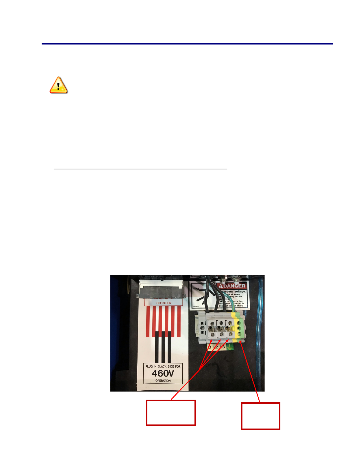
TW4300 Setup and Installation
Preparing the Unit for Primary Power
Only qualied personnel should perform this installaon.
Turn the input power o at the disconnect switch or fuse box before working on
the welder
Do not touch electrically hot parts
Primary Power Cable and Ground Connecon
Remove the top cover of the TW4300
Route the primary power cable through the power inlet hole in the top le
corner on the backside of the welder with enough slack to reach the terminal
block
Connect the ground wire to the frame of the welder as shown below
Connect the power leads (black, white, red) to the L1, L2, and L3 connectors on
the terminal block, as shown below
9
Power
Connecons
Ground
Connecon
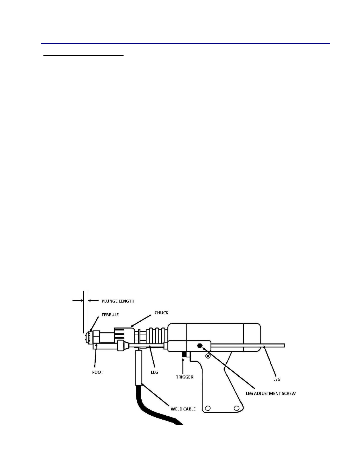
Stud Gun Setup
TWE19000Gun Setup
Each stud welding applicaon requires that the stud gun be set up properly for the cor-
rect stud and ferrule arrangement.
Select the correct style and size of chuck and aach it to the stud gun
Select the appropriate length leg assembly, foot piece, and ferrule grip
Secure ferrule grip to the foot piece
Tighten leg screws and washers to the foot piece and slide the legs through the
front cap nuts
Aer the accessories have been mounted to the stud gun place a stud into the chuck
and begin the alignment of the accessories.
Fully seat a stud into the chuck so that the stud is held rmly
Insert a ferrule into the ferrule grip
Move the leg, foot and ferrule assembly so that the stud protrudes beyond the fer-
rule
1/8” sck out for studs 1/2" and smaller in diameter
3/16” sck out for 5/8” diameter studs
Posion the ferrule grip assembly so that the stud moves freely through the ferrule
when li is simulated
10

Stud Gun Setup
Li:
Set the li when all of the accessories and stud have been properly set on the stud
gun and prior to welding. Plug the stud gun control connector directly into the stud
welder (do not aach the weld cable). Turn on the stud welder and actuate the trigger
of the stud gun with the stud and ferrule in place. Note the retracon of the sha of
the stud gun, this is designated as the li.
The li seng should be approximately 3/32” for general welding applicaons and
studs ranging up to 3/4” in diameter. Larger diameter studs and select applicaons
should have an 1/8” li seng.
Adjusng the li:
Remove the back cap of the stud gun
Loosen the two socket set screws around the periphery of the li adjustment
screw
To increase li rotate the li adjustment screw counter clockwise and to decrease
li rotate clockwise
With each turn check the li by actuang the stud gun unl the desired li is
achieved
Tighten the socket set screws to hold the li adjustment screw in place to secure
the selected seng
Replace the back cap of the stud gun
Rear coil yoke
Set screw
Li adjusng screw
Gun body
11
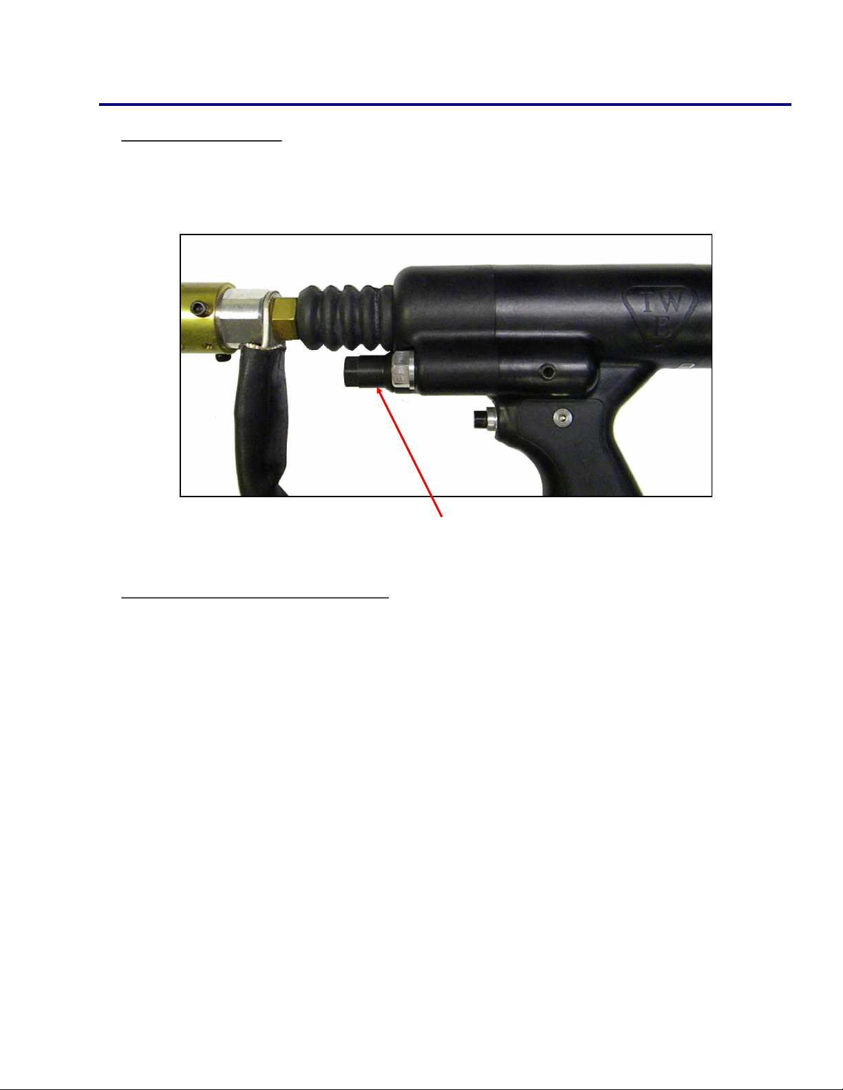
Stud Gun Setup
Free Travel Adjustment
This adjustment can be used to control the force with which the stud is plunged into the molten
weld pool by moving the engagement point of when the sha of the stud gun engages the damp-
ener. Rotang the dampener cover counter clockwise increases the amount of free travel.
Dampener cover
12
Aaching the stud gun to start welding
Select the gun, control cable, and weld cable that is recommended for the specic type of
welder and job
Aach stud gun to weld and control cable extension
Actuate the stud gun without placing it on the surface to be welded to assure that the
connecon through the control cable is correct to complete the circuit
Conrm me and current sengs are correct
Place the selected stud into the chuck and aach the ferrule to the ferrule grip
Place stud onto surface to be welded and press stud gun down unl ferrule is ush with the
welding surface
Trigger the gun and hold in place unl cycle is completed
Pull gun assembly straight up o of the welded stud
Do not depress trigger when removing gun from stud
Remove the ferrule by breaking it o and inspect the weld
Make proper adjustments if needed

TW4300 Cable Connection
Ground Cable Connecons
The TW4300 is equipped with one ground cable connecon located at the
boom le on the front of the machine below the power switch
Tighten the ground cable to machine by rotang the connector clockwise and
then secure the C-clamp to the work surface
Weld Cable Connecons
The TW4300 has one weld and control cable connecon on the front of the
welder labeled gun and control
Tighten the weld cable to the machine by rotang the connector clockwise
Plug the male control cable connector to the female panel mount labeled control
13
Weld cable connecon
Control cable connecon
Ground connecon

TW4300 Operation
TW4300 Power Switch/Power On
The power switch for the TW4300 is located on the right
front of the welder’s control panel. O posion is vercal
with the “O” showing. On posion is horizontal with the “I”
displayed.
When the welder is turned on, the digital display will go
through a self-diagnosc check. This takes approximately 3
to 5 seconds, and then the digital display will show the last
me and current seng. Once the me and current is
displayed, the unit is ready to weld. When connected to the
welder, the stud gun will actuate 3 mes, indicang that
there is a good connecon.
TW4300 Control Panel
Brightness Switch — LED brightness can be set to indoor or outdoor brightness levels
Time Buon — Used to adjust me sengs
Current Buon — Used to adjust current sengs
Digital Display — Displays weld sengs, machine presets, or weld counters
Diagnosc LED — Used to determine an issue with weld/control cable or machine
Fine/Coarse Switch — Can be selected to adjust me or current by 10th’s or 100th’s
Menu Opons — Shows which menu the machine is displaying
Adjustment Dial — Used to toggle through menus or adjust the me and current
Supervisor Lock — Locks the machine so changes cannot be made to the weld sengs
Brightness Switch
Adjustment Dial
Current Buon
Digital Display
Time Buon
Fine/Coarse Switch
Supervisor Lock
Menu Opons
Diagnosc LED
14

TW4300 Operation
Menu Selecon
By depressing the adjustment dial and rotang clockwise or counter clockwise a
menu can be chosen. The menus include weld sengs, welding presets, job
counter, and a lifeme unit counter.
Menu Selecon:
1. Verify supervisor lock is o
2. To chose a menu, depress and hold down the adjustment dial
3. Turn adjustment dial clockwise or counter-clockwise to cycle through the
dierent menu opons
4. Stop rotang the dial when the LED for the desired menu is illuminated
5. Release the adjustment dial
Adjustment dial
Supervisor lock
Menu opons
15

TW4300 Operation
Weld Sengs - Time and Current
The me and current controls are located on the front of the welder. The controls
consist of a me buon, current buon, adjustment dial, ne/coarse switch, and a
supervisor lock. The digital display will indicate the sengs chosen during setup.
Adjusng the Time Seng:
1. Verify the supervisor lock is o
2. Set the FINE/COARSE switch to the desired posion
3. Press and hold the TIME buon
4. Turn the dial to adjust the seng
5. Release the TIME buon
Adjusng the Current Seng:
1. Verify the supervisor lock is o
2. Set the FINE/COARSE switch to the desired posion
3. Press and hold the AMPS buon
4. Turn the dial to adjust the seng
5. Release the AMPS buon
Seng the Gas Purge Time:
1. Depress and hold both the TIME and AMPS buons then turn adjustment dial
2. The purge me is saved when the buons are released
Adjustment dial
Current buon
Digital display
Time buon
Fine/Coarse switch
Supervisor lock
16

TW4300 Operation
Preset Menu
The full range of studs the machine is capable of welding is preloaded onto the unit
for fast and easy access. Any combinaon of me and current can also be saved to a
programmable preset locaon.
Selecng Custom Presets:
1. Navigate to the Preset Menu
2. Rotate the dial counter-clockwise to the desired preset
3. Press and release dial
Saving Custom Presets:
1. Set the weld sengs to the sengs to be saved
2. Navigate to the Preset Menu
3. Navigate to the desired custom preset
4. Press and hold the dial in unl the menu switches back to the Weld Sengs
Menu
Selecng a Factory Preset:
1. Navigate to the Preset Menu
2. Rotate the dial clockwise to the desired stud diameter
3. Press and release the dial
Exing back to the Weld Sengs Menu (all available opons):
1. Navigate to the Weld Sengs Menu using the dial method listed previously
2. Turn the dial to the end of the custom preset opons, press and release the dial
3. Turn the dial to the end of the factory preset opons, press and release the dial
4. Press and release the AMPS or TIME adjustment buons
17
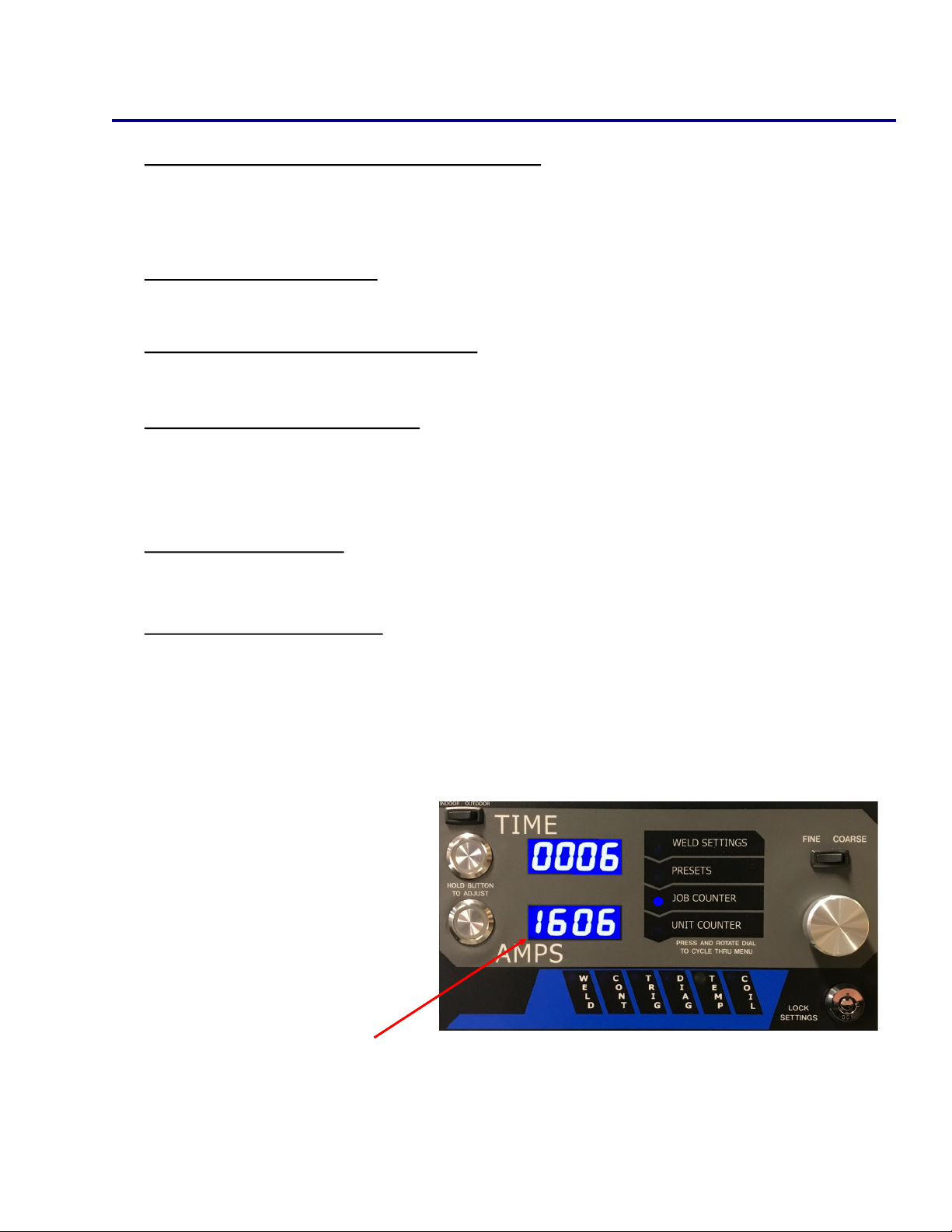
TW4300 Operation
Weld Counter and Weld Counter Reset
The TW4300 is equipped with two dierent counters to display the number of mes
the unit has drawn an arc.
Job Counter (Reseable) - Is a running total of the number of welds since the coun-
ter was last reset. This counter can easily be reset from the job counter menu.
Unit Weld Counter (Non-reseable) - Is a running total of every me an arc is drawn
on the machine. This is programmed from the factory and can not be reset.
Reseng The Job Counter:
1. Navigate to the Job Counter Menu
2. Press and hold the dial in unl the counter changes to 0
Viewing Unit Counter:
1. Navigate to the Unit Counter Menu
Exing Unit/Job Counter: - To exit the counter menu navigate to the weld sengs
menu using the dial method or press and release the AMPS or TIME adjustment
buons.
Job counter will display here
18
Table of contents
Other Truweld Welding System manuals

Truweld
Truweld TW55000 User manual

Truweld
Truweld TW5700 User manual

Truweld
Truweld ARWSC900 User manual

Truweld
Truweld TWE - 19000 User manual

Truweld
Truweld TW4400 User manual

Truweld
Truweld TWE - SC1900 User manual

Truweld
Truweld TW6900 User manual

Truweld
Truweld TW5600 User manual

Truweld
Truweld TWE - SC3402 User manual

Truweld
Truweld TWE-SC1950 User manual


Popular Welding System manuals by other brands


Forney
Forney Easy Weld 261 quick start guide

Hobart Welding Products
Hobart Welding Products Handler 125 EZ Specification sheet

Lincoln Electric
Lincoln Electric VANTAGE 400 CE Operator's manual

Adler
Adler MMA-175 instruction manual

Deca
Deca EASYJOB 220 instruction manual

Lincoln Electric
Lincoln Electric POWER MIG 255 SVM144-B Service manual