Drawell TURBO T Series User manual

Please read operating manual before installation and operation.
Drawell International Technology Limited
Shanghai Drawell Scientific Instrument Co.,Ltd
Add : Suite 1101,Lane561 XiuChuan Rd., Greeland Max-Mall,PuDong,Shanghai,China
Tel: 0086 21 50966080
Fax: 0086 21 50966080
Web : www.drawell.com.cn
Email : sales01@drawell.com.cn

TURBO T SERIES ROTARY VANE
VACUUM PUMP
Operating Instructions
PRODUCT MODEL:
T8
T16
T30
T40
T60

CONTENTS
0 Safety Instruction
0.1 Mechanical Injury----------------------------------------------------------------------------------------------- 2
0.2 Electrical Hazard------------------------------------------------------------------------------------------------ 2
0.3 Heat Injury--------------------------------------------------------------------------------------------------------2
0.4 The Injury from Materials------------------------------------------------------------------------------------- 3
0.5 Explosion Hazard----------------------------------------------------------------------------------------------- 3
0.6 Noise Hazard----------------------------------------------------------------------------------------------------- 3
0.7 Risk of Pump Damage------------------------------------------------------------------------------------------3
1 Overview
1.1 Summarize ------------------------------------------------------------------------------------------------------ 4
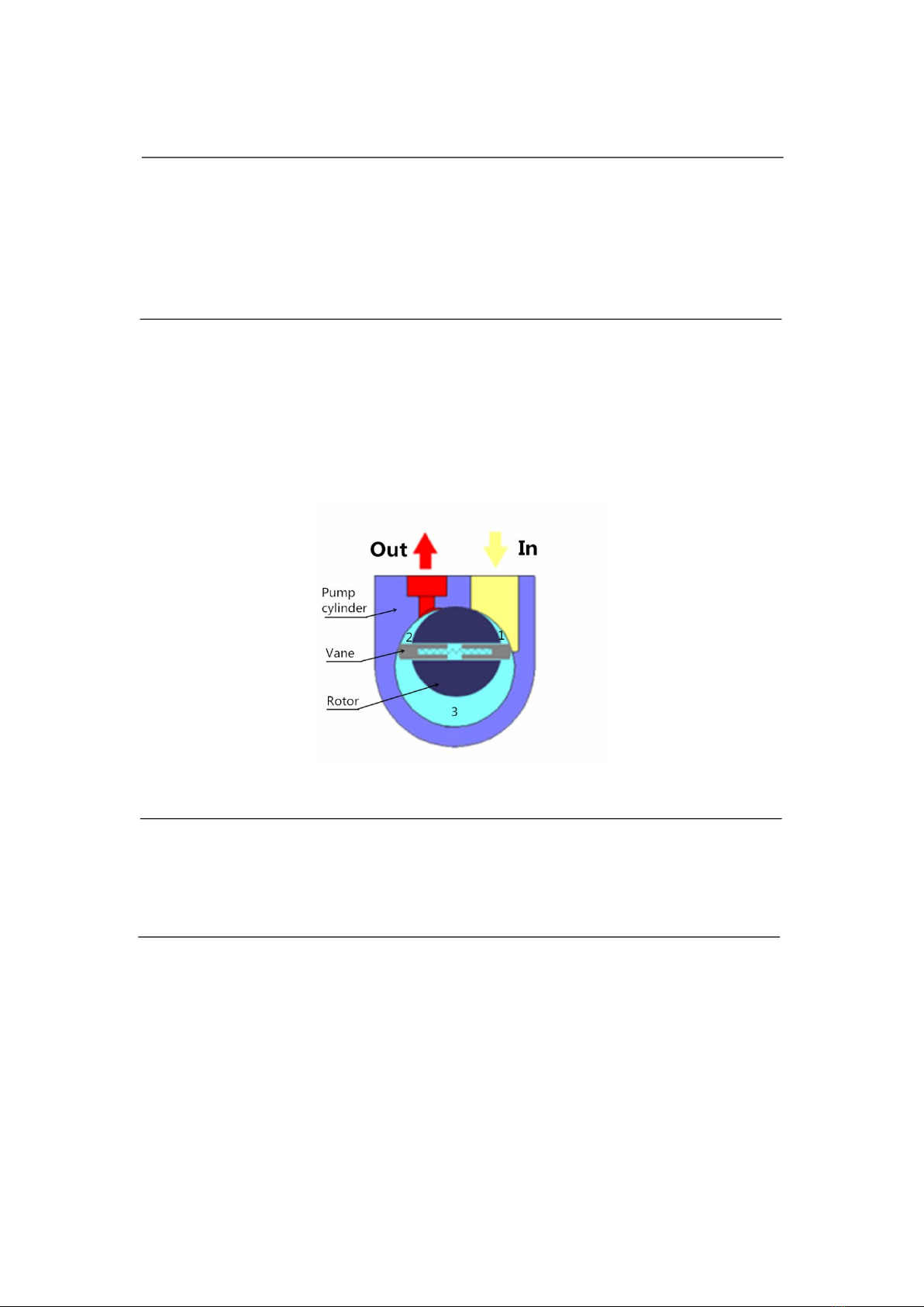
1.2 Working Theory ------------------------------------------------------------------------------------------------4
1.3 Lubrication ------------------------------------------------------------------------------------------------------4
1.4 Configuration ---------------------------------------------------------------------------------------------------4
1.5 Optional Accessories ------------------------------------------------------------------------------------------ 5
1.6 Technical Data --------------------------------------------------------------------------------------------------5
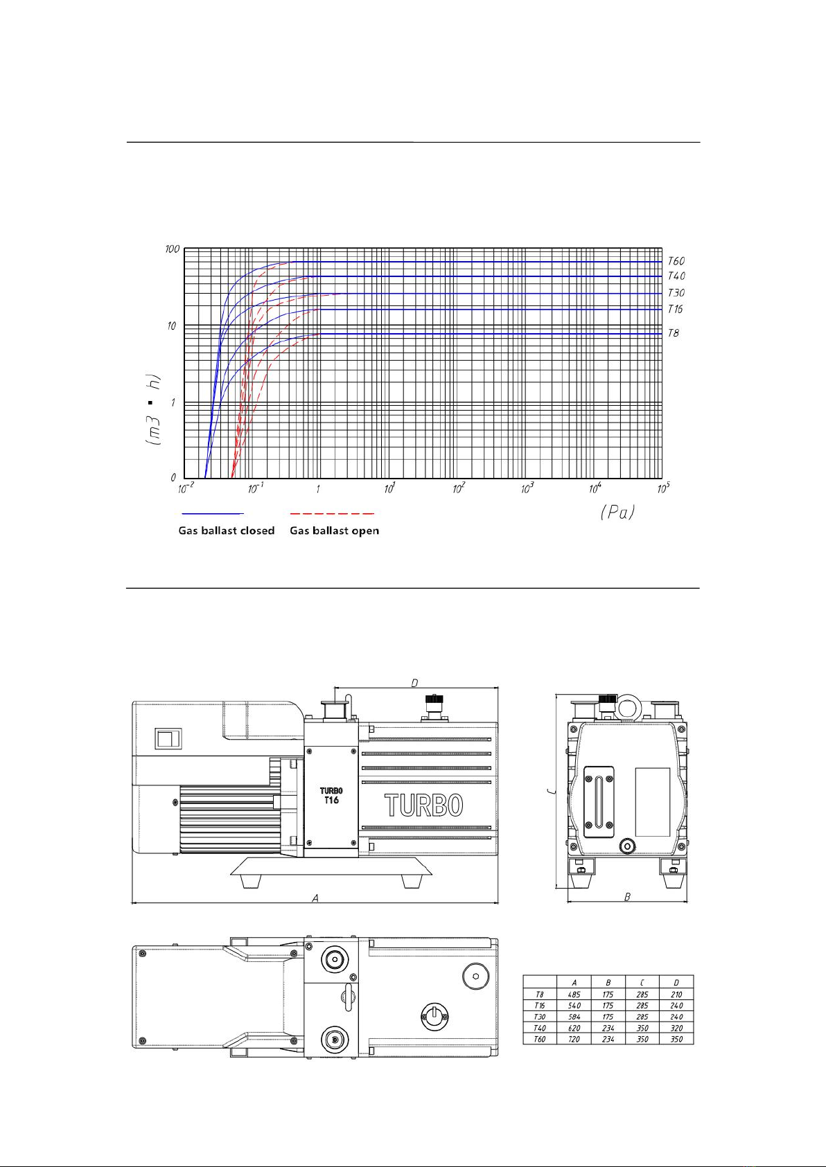
1.7 Pumping Speed -------------------------------------------------------------------------------------------------6
1.8 Size Details ----------------------------------------------------------------------------------------------------- 6
2 Installation
2.1 Placement ------------------------------------------------------------------------------------------------------- 7
2.2 Application ------------------------------------------------------------------------------------------------------7
2.3 Vacuum System Connection --------------------------------------------------------------------------------- 8
2.4 Electrical Connection ----------------------------------------------------------------------------------------- 8
3 Operation
3.1 Start-up ---------------------------------------------------------------------------------------------------------- 9
3.2 Noise ------------------------------------------------------------------------------------------------------------- 9
3.3 Stop Pumping ---------------------------------------------------------------------------------------------------9
3.4 Control System -------------------------------------------------------------------------------------------------9
4 Maintenance
4.1 Maintenance Plan -------------------------------------------------------------------------------------------- 10
4.2 Important Note ------------------------------------------------------------------------------------------------10
4.3 Warranty ------------------------------------------------------------------------------------------------------- 10
5 Trouble Shooting -------------------------------------------------------------------------------------------- 11
6 Spare Parts --------------------------------------------------------------------------------------------------- 12

3
REMARK
Thanks for reading!
In order to get the optimum condition and safe operation,please read this manual carefully before installation.
Only operate TSVP®T SERIES VACUUM PUMP in a proper way according to operating manual can
ensure the safety and efficient operation of the pump.TSVP®T SERIES VACUUM PUMP can only be
operated under the proper condition or the described environment as this manual shows. The product can only be
operated by the skilled technician.
About some special requirement and rules, please check with your local related department.
About the operation and maintenance, please check with our sales department or our local distributors if have.
DANGEROUS means the emergency dangerous situation,will cause severe injury or even death if not take care.
KEEP OUT means there has the potential dangerous, will cause some damage if not take care.
There has no harm here, just to inform some important points about installation,operation or maintenance
TSVP®T SERIES VACUUM PUMP is not suit for:
Contains dust, active,flammable explosive gas
Oxygen concentrations higher than 21%
Under the flammable explosive condition
We reserve the right to modify the design and specified data including operating manual without notice.

4
0 SAFETY INSTRUCTION
0.1 Mechanical Injury
1 Do not expose yourself under the vacuum environment
2 Do not start the pump once the inlet port is not sealed
3 Please operate horizontally, or not over 10 degree inclination
4 Please move the pump horizontally once it is filled with oil
5 Please make sure the exhaust port is not blocked
6 Please always move the pump by the flying rings
0.2 Electrical Hazard
1 The electric connecting should be handled by skilled technician, and observe the local regulation
2 Please blackout the power before any maintenance
3 Please keep the connecting line out of wet condition or any bad condition,to avoid any damage
4 Please make the correct grounding connection to avoid static electricity
0.3 Heat Injury
1 Temperature will go higher than 70℃(158℉) under some certain circumstance ,it will be have the potential to
get a burn. So please wear the safety gloves if have to operate the pump once it still hot.
2 It is better to wait till the pump is cool before any operation
3 Please always keep attention on the caution information, if the identity is being removed or covered, please
always put it ahead of the pump again.

5
0 SAFETY INSTRUCTION
0.4 The Injury from Materials
1 Do not pump oxygen(>21% oxygen concentration)
2 Please make sure the pumped gas is mutual consistency with the pump,to avoid any chemical reaction
3 Do not pump the toxic,radiation or spontaneous combustible materials
4 If the pump have pumped the toxic gas, please wear the safety equipment before open the exhaust port, and
please also mention it before sending it to maintenance department.
5 Please make sure the cleanser is mutual consistency with the pump and do not leave any cleanser inside the
pump when washing the pump, to avoid any chemical reaction
0.5 Explosion Hazard
1 Do not operate in the explosion endangered area
2 Do not pump flammable and explosive gas
0.6 Noise Hazard
1 the Noise level of TSVP®T SERIES VACUUM PUMP is less than 60db(A), please wear some
protective equipment if needed.
0.7 Risk of Pump Damage
1 Please make sure the safety motor connection, refer to the chapters about how to connect the circuit
2 Do not pump the gas contains some dust or viscosity residue. Or if you have to, please contact with us to get
some professional advises.
3 The exhaust line should preferably be installed with a downward slope so as to prevent condensate from
flowing back into the pump and contaminating the oil. Please periodically drain the condensed oil in the exhaust
pipe from avoiding of exhaust pipe block. If the exhaust line has an upward slope, please install a condensate trap
4 Please make sure to avoid any dust or fluid inside the pump

6
1 Overview
1.1 Summarize
TSVP®T SERIES VACUUM PUMP is the double stage oil sealed rotary vane vacuum pump,the
number shows in the model(8,16,30,60) means the pumping speed, unit m3/h
TSVP®T SERIES VACUUM PUMP can only pump the gas,and not suitable with harmful gas or
corrosive gas.
1.2 Working Theory
As shown in fig.1 functional diagram:
The rotor, mounted eccentrically in the pump cylinder,has 2 vanes which divide the pump chamber into two
different changeable compartments.
When the pump rotor which was driven by the motor clockwise rotated, chamber 1 will such air from small to
big, and chamber 2 will complete the transmission of air, then chamber 3 will compress and exhaust air from big to
small, and complete a work cycle from suction-compress-exhaust finally, achieve the vacuum of the system.
(fig. 1)
1.3 Lubrication
We will equip the pump oil along with the pump, TPO-68
If you want to buy additional pump oil, please contact with our sales department
1.4 Configuration
All the pump will be equipped with the motor:
Single phase can be start instantly
Three phase motor should be connected by a skilled electrician.
Below items will be delivered along with the pump:
Operation instruction---1copy
Clamp(KF25 or KF40)---2pcs
Pump Oil---1bottle

7
1 Overview
1.5 Optional Accessories
Apply to T8/T16
Oil mist collector, KF25
Air inlet filer, KF25
Apply to T40/T60
Oil mist collector, KF40
Air inlet filer, KF40
Connector for T8/T16
KF25 bend
KF25 clamp
Connector for T40/T60
KF40 bend
KF40 clamp
1.6 Technical Data
T8
T16
T30
T40
T60
50Hz Nominal Pumping speed M³/h(L/s)
9.2/2.6
17.0/4.7
31.4/8.7
42/11.7
63/17.5
50Hz Pumping speed M³/h(L/s)
7.3/2.0
14.8/4.1
28.9/8.0
39.6/11
59/16.4
Partial Ultimate Pressure without
gas ballast (Pa)
5×10⁻²
5×10⁻²
5×10⁻²
4×10⁻²
4×10⁻²
Total Ultimate Pressure without gas ballast
(Pa)
8×10⁻¹
4×10⁻¹
4×10⁻¹
4×10⁻¹
4×10⁻¹
Total Ultimate Pressure with gas ballast
(Pa)
2×10⁻¹
6×10⁻¹
6×10⁻¹
6×10⁻¹
6×10⁻¹
vapour allowed pressure (Pa)
15
20
25
25
25
vapour pumping ability (g/h)
100
230
800
1000
1100
Oil Capacity(min/max) L
0.7/1
1.4/1.8
3/4
3/4
4/5
Noise Level(gas ballast close/open)(db a)
56/58
58/60
58/60
58/60
58/60
Ambient Temperature ℃
12-45
12-45
12-45
8-45
8-45
Connector
KF25
KF25
KF25
KF40
KF40
Power Supply
Single/3-ph
Single/3-ph
Single/3-ph
Single/3-ph
3-ph
Power Rating(kw)
0.37
0.55
0.75
1.1
1.5
Dimensions (mm)
485×185×270
540×185×270
585×185×270
660×240×350
720×240×350
Weight(without oil)kg
21
36
40
65
75
Remarks:
According to JB/T6533-2017 related standards,by the measured from Seat type McLeod Vacuum
Gauge,with TS68# pump oil.
If the pump started under the rated voltage, will coming up with the delay start.

8
1 Overview
1.7 Pumping Speed
1.8 Size Details

9
2 Installation
Please be noted the potential risk before the installation,
follow the safety instructions 0.1-0.7
2.1 Placement
The pump should be set up on a flat(on less than 10 degree gradient)and firm surface,cause oblique installation
may result in pump’s vibration, high noise or even damage. And the pump must be lower than the machine, in
order to prevent siphonage.
And please be noted that the ambient temperature should be between 12℃~45℃(55℉~113℉)
If the installation site is higher than sea level 1000m, or the humidity is higher than 90%, please contact with us
first.
2.2 Application
TSVP®T SERIES VACUUM PUMP can only pump gas,to achieve the high vacuum of the vessel.
We do not suggest to pump the gas contains dust, but if you have to,please add some protection device, or you can
contact with us, our technician can offer some suggestion for you.
If the gas contains high moisture content,we suggest to equip the liquid separator before&after the pump, and also
open the gas ballasting.
Do not pump any of the following:
Radioactive substances
Toxic substances
Flammable substances
Corrosive substances
Oxygen(concentration>21%) or other high-activity gas
Fluid or any dustiness gas

10
2 Installation
2.3 Vacuum System Connection
Please tear down the sealing element(plastic cap) before connection
Please keep the sealing element for storage purpose
Please make the connection by using the clamp and center ring
Please always keep the intake line clean and tidy, or it will have a strong impact on vacuum degree
The connecting lines between vacuum pump and vacuum system should be as short as possible
If the exhaust gas should be collected,then the exhaust line should be as big as possible and clean and tidy, to
avoid explosion
If no exhaust line,then we suggest to install a discharge filter or oil mist filter
Do not operate the pump with sealed exhaust port,to avoid explosion
The exhaust line should preferably be installed with a downward slope so as to prevent condensate from
flowing back into the pump. But if not workable, then we suggest to install a cold trap
2.4 Electrical Connection
The electrical connection should be handled by the skilled electrician, and obey the local regulation such as
EN60204-1
Please always cut off the power supply during connection,and also install the integrated control system to avoid the
malfunction of the main power. And obey the safety instruction 0.2
2.4.1 Single Phase(220V) Motor
Please choose the suitable fuse wire according to the nameplate on the motor, and equip with the suitable socket.
The motor is equipped with the overload protection device. So when the motor stopped because of overheating,
please shut down the power if you will have any operation on the pump, because the motor will be start
automatically once it is being cool down.
2.4.2 Three Phase Motor
The pump is supplied without any accessories of electrical connection. Please using the appropriately rated cable
and a suitably rated motor protection switch, the value set on the motor protection switch must correspond to the
current rating stated on the nameplate of the motor.

11
3 Operation
3.1 Start-Up
Check the oil level before start-up, do not start under the minimum oil level.
3.1.1 Noise
The noise of initial start-up will be louder than normal running,especially under low temperature. It is because of
that viscosity of the oil is higher under low temperature,which makes the vane not so easy for running. But the
noise will be low down after a while.
3.2 Operation
The suitable ambient temperature should be between 12℃~45℃(55℉~113℉).
The pump body will be higher than 70℃(156℉) on the working,so please be careful about the risk of heat injury.
3.3 Stop pumping
If the pump was stopped using for a long time, please cover the inlet and exhaust port, in case of the dust may
pollute the pump.
Gas will be dissolved in the pump oil when putting the pump out of operation for long, it is recommended to let the
pump continue to operate for 30mins with the intake line closed and the gas ballast valve open. The pump cam
resume normal use after the pump be degassed.
3.4 Control System
Please install the Integration Control System to avoid any accident of the main power, it will make the pump can
only be started by hand,which is so called emergency stop equipment

12
4 Maintenance
4.1 Maintenance Plan
There will be no so much maintenance if use the pump under the normal conditions.
NO.
ITEM
TIMELINE
REMARK
1
Check the oil level
Before start-up, daily maintenance
Switch the power off
2
Check the oil quality
Before start-up, daily maintenance
The oil should be transparent
3
Clean the inlet port
Every 6 month under normal condition
Observe the local regulation
4
Exchange the oil
After 2000 hrs continuousrunning
After the pump is cool down
5
Clean the view window
Once invisibility
Observe the local regulation
6
Clean the motor fan
Every 6 month under normal condition
Switch the power off
4.2 Important Note
Please always switch the power off before take the pump apart, make sure the pump will not active accidentally,
and observe safety instruction 0.2
Only the related skilled person can doing the related work,inappropriate maintenance will affect the service life
and the performance
If the pump operated under the normal condition,there will be no need for depot repair, you just need to observe
the above maintenance plan.
If the pump have to return to depot, please always contact with us first, there has a file need to be done, and you
have to send the filled file together with the pump, or our maintenance department will return the package back.
4.3 Warranty
TSVP vacuum pump has a one year guarantee from the buying date.
Our company will provide maintenance service free of charge in the period of guarantee provided on the
normal use according to the operating manual.
In case of following failures, repair fare is needed:
1. Malfunction by nature disasters or artificial factor
2. Malfunction under special usage
3. Malfunction of damageable spare parts
4. Malfunction by non-normal operation or error use which is identified by our technical engineer

13
5 Trouble Shooting
Trouble
Possible reason
Solution
Pump can not be
started
1.Out of electrical
1.Check the connection of power supply
2.Operation voltage is abnormal
2.Voltage wave within 10%
3.Motor is malfunctioning
3.Replace the motor
4.Pump is jammed
4.Repair the pump
5.Out of operation for long, liquid and organic
solvents result rust of the pump body
5.Repair the pump
6.Pump inner accessories are damaged
6.Repair the pump
Pump can not
reach the
maximum
pressure
1.Pump is too small to suit for the machine
1.Replace the pump
2.Measuring technique or gauge is unsuitable
2.Use the correct measuring technique and
gauge,measure the pressure directly at pump's
intake port.
3.Oil level is too low
3.Add Oil
4.Vacuum system leak
4.Check the leakage(sealing element)
5.Exhaust valve is malfunctioning
5.Repair the valve
6.Lubricate seal oil channel inside pump
blocked
6.Clean oil channel
7.Oil is unsuitable or deteriorated
7.Change the oil(Pump Oil only)
Oil seal leak
1.Oil seal broken
1.Replace new oil seal
2.Seal ring was deformed
2.Replace new seal ring
Abnormal voice
1.Motor is malfunction
1.Voltage wave within 10%
2.Coupling element is worn
2.Install new coupling element
3.Vane spring is broken
3.Replace the vane spring
4.Foreign material into the pump
4.Clean the pump body
5.Parts of screw loosed
5.Check the parts and tighten the screw
Overtemperature
1.Continuous operation under high pressure in
the intake port
1.Shorten exhaust time as far as possible
2.Process gas is too hot
2.Set up something like cold trap
3.Cooling air supply is obstructed
3.Set pump correctly
4.Oil cycle is obstructed
4.Clean the oil channels
5. Ambient temperature is too high
5.Cooling the temperature
Oil injection
1.Too much oil in the pump
1.Drain some oil
2.Continuous operation under high pressure in
the intake port
2.Shorten exhaust time as far as possible
Oil drain back
1.Misalignment between the check valve and
the inlet opening
1.Reset them
2.Misalignment of exhaust valve
2.Reset it
3.Impurities in the exhaust valve ports
3.Clean the impurities

14
6 Spare Parts
Item
Qty
Description
Material
Remark
Item
Qty
Description
Material
Remark
1
1
Motor
45
2
Screw M6*6
2
4
Screw M8*20
SUS304
46
1
Screw M6*6
∅0.6
3
4
Spring washer M8
SUS304
47
1
Screw M10*10

15
4
9
Screw M5*10
48
3
Cylinder pin ∅4*8
5
9
Spring washer M5
49
1
Rotor
40Cr
6
1
Fan for coupling
50
2
HV vanes
7
2
Key C6*20
51
1
FV cylinder
HT250
8
2
Screw M5*10
52
2
Exhaust valve
Fluorelastomer
9
2
Coupling
45
53
2
Exhaust valve spring
carbon Spring-steels
10
1
Reinforcement ring
45
54
1
Exhaust cover cap
SUS304
11
1
Drive rubber ring
Oil resistant rubber
55
1
Exhaust plate
SUS304
12
2
Screw M6*14
SUS304
56
1
Screw M5*6
13
2
Washer M6
SUS304
57
1
Screw M5*6
∅0.3
14
1
Inlet port KF25
ZL104
58
1
O-ring
Fluorelastomer
∅69*3
15
1
O-ring
Fluorelastomer
∅43*2.4
59
2
FV vanes
16
1
O-ring
Fluorelastomer
∅25.8*2.65
60
1
End plate
HT250
17
1
Anti-suck back,KF25
ZL104
61
3
Screw M8*100
18
1
Coupling housing
ZL104
62
3
Washer M8
19
8
Screw M4*6
63
1
Pipe clamp
Q235
20
2
Side plate
Q235
64
1
Oil return pipe
Q235
21
2
Foot
Q235
40*25
65
1
GB cap FPM
Oil resistant rubber
22
4
Nut M6
66
1
GB valve Body
ZL104
23
4
Rubber foot
67
1
GB Non-return valve
Oil resistant rubber
24
4
Screw M6*12
68
1
Pipe clamp
25
4
Washer M6
69
1
GB valve stem
SUS304
26
4
Screw M6*14
70
1
O-ring
Fluorelastomer
∅6*2
27
1
Screw M10*50
71
1
O-ring
Oil resistant rubber
∅24*1.9
28
1
Screw M10*20
72
2
Screw M4*12
SUS304
29
1
Handle
45
73
2
Washer M4
SUS304
30
1
Exhaust port KF25
ZL104
74
1
Oil plug G3/4
31
1
O-ring
Fluorelastomer
∅28*3
75
1
O-ring
Oil resistant rubber
∅28*2.5
32
1
O-ring
Fluorelastomer
∅85*3
76
4
Washer M6
SUS304
33
1
O-ring
Fluorelastomer
∅199.4*3.1
77
4
Screw M6*25
SUS304
34
1
Seal plug
Fluorelastomer
78
1
Oil casing
ZL104
35
1
Piston spring
carbon Spring steels
79
1
Gasket
Oil resistant rubber
36
1
Piston
SUS304
80
1
Oil plug M16*1.5
37
3
Shaft seal
Oil resistant rubber
81
1
Gasket oil sight glass
Fluorelastomer
∅60*3.1
38
3
Screw M5*30
82
1
Disk for oil sight glass
Glass
39
1
Shaft seal retainer ring
HT250
83
1
Bracket oil sight glass
ZL104
40
1
O-ring
Fluorelastomer
∅48*2.4
84
4
Screw M5*12
SUS304
41
2
Oil pump vane
85
1
Gas ballast kit
42
1
HV cylinder
HT250
86
1
Oil sight glass unit
43
3
Spring washer M8
87
1
Pump module
44
3
Screw M8*25
88
2
Pump foot
This manual suits for next models
5
Table of contents
Popular Water Pump manuals by other brands

BUSCH
BUSCH Dolphin LX 0030 A Installation and operating instructions

Taco Comfort Solutions
Taco Comfort Solutions Hot-LinkPlus HLPE-1 instruction sheet

Wetelux
Wetelux 82 06 93 instruction manual

Grundfos
Grundfos DMX 227 Installation and operating instructions

WAGNER
WAGNER EvoMotion 5-125 Original operating manual

STA-RITE
STA-RITE DURA-JET 5JSAC-A owner's manual

Tunze
Tunze Master electronic Instructions for use

Hyundai
Hyundai DHY50E user manual

Graco
Graco Endura-Flo 4D150 Instructions - parts

Grundfos
Grundfos SP Installation and operating instructions

Becker
Becker U 4.100 operating instructions

GORMAN-RUPP
GORMAN-RUPP T4A3-B Installation, operation and maintenance manual