Dream Vision DreamScaler4 User manual


2 R699761 - DreamScaler 4 User Manual
Changes
DreamVision provides this manual ’as is’ without warranty of any kind, either expressed or implied, including but not
limited to the implied warranties or merchantability and fitness for a particular purpose. DreamVision may make
improvements and/or changes to the product(s) and/or the program(s) described in this publication at any time
without notice.
This publication could contain technical inaccuracies or typographical errors. Changes are periodically made to the
information in this publication; these changes are incorporated in new editions of this publication.
Copyright
All right reserved. No part of this document may be copied, reproduced or translated. It shall not otherwise be
recorded, transmitted or stored in a retrieval system without the prior written consent of DreamVision.
Guarantee
DreamVision provides a guarantee relating to perfect manufacturing as part of the legally stipulated terms of
guarantee. On receipt, the purchaser must immediately inspect all delivered goods for damage incurred during
transport, as well as for material and manufacturing faults. DreamVision must be informed immediately in writing of
any complaints.
If the purchaser or third party caries out modifications or repairs on goods delivered by DreamVision, or if the goods
are handle incorrectly, in particular if the systems are commissioned operated incorrectly or if, after the transfer of
risks, the goods are subject to influences not agreed upon in the contract, all guarantee claims of the purchaser will
be rendered invalid. Not included in the guarantee coverage are system failures which are attributed to programs or
special electronic circuitry provided by the purchaser, e.g. interfaces. Normal wear as well as normal maintenance
are not subject to the guarantee provided by DreamVision either.
The environmental conditions as well as the servicing and maintenance regulations specified in this manual must
be complied with by the customer.
Trademarks
Brand and product names mentioned in this manual may be trademarks, registered trademarks or copyrights of
their respective holders. All brands and product names mentioned in this manual serve as comments or examples
and are not to be understood as advertising for the products of their manufactures.

R699761 - DreamScaler 4 User Manual 3
Table of Contents
1.0 GETTING STARTED ................................................................................................................... 5
1.1 Introduction........................................................................................................................ 5
1.2 Unpacking and Inspection ................................................................................................. 5
1.3 Display Compatibility Requirements.................................................................................. 5
2.0 GETTING STARTED ................................................................................................................... 6
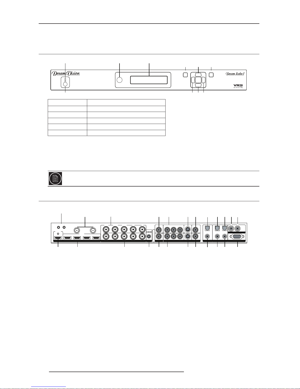
2.1 Front Panel Overview ........................................................................................................ 6
2.2 Rear Panel Overview......................................................................................................... 6
Video Inputs Compatibility..................................................................................... 6
Video Outputs........................................................................................................ 7
Audio Inputs .......................................................................................................... 7
Audio Outputs........................................................................................................ 7
12V Triggers Outputs............................................................................................. 7
Power Supply Input ............................................................................................... 7
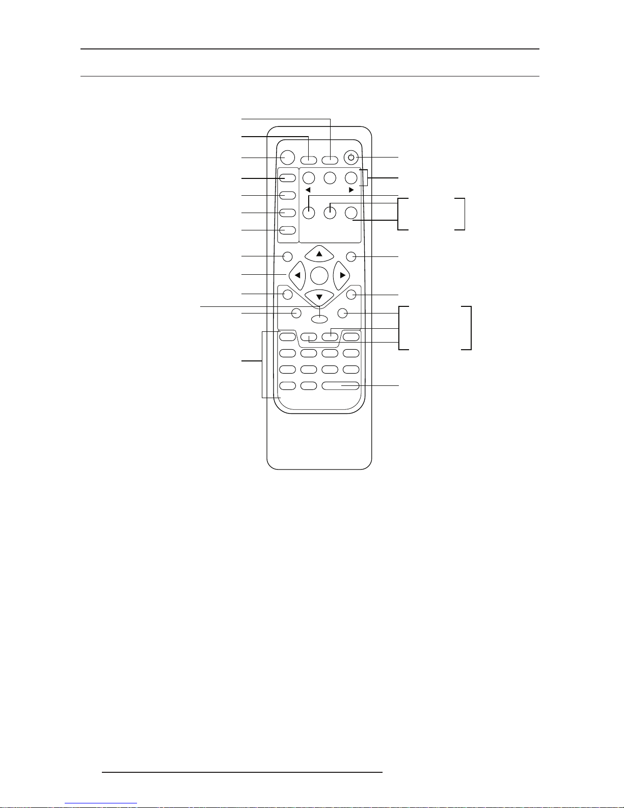
2.3 Remote Control Overview ................................................................................................. 8
Power/Standby Buttons ......................................................................................... 8
Curtain Button ....................................................................................................... 8
Remote Control Battery Installation ...................................................................... 8
Menu Navigation ................................................................................................... 9
THEATRE Mode .................................................................................................... 9
Info Screen Button................................................................................................. 9
3.0 SETUP....................................................................................................................................... 10
3.1 Initial Set-Up .................................................................................................................... 10
STEP 1 - Power Up ............................................................................................. 10
STEP 2 - Connect the scaler to your display....................................................... 10
STEP 3 - Connecting your Sources to the DreamScaler 4 ................................. 11
3.2 Audio Operation............................................................................................................... 11
4.0 MENU OPTIONS ....................................................................................................................... 12
4.1 Input Select...................................................................................................................... 12
4.2 Input Aspect Ratio Control............................................................................................... 12
Frame Aspect Ratio............................................................................................. 13
Active Aspect Ratio ............................................................................................. 13
DreamScaler 4 Image Mapping........................................................................... 13
Panorama ............................................................................................................ 14
Zoom ................................................................................................................... 14
Pan ...................................................................................................................... 14
Borders................................................................................................................ 14
Presets ................................................................................................................ 14
4.3 Input Adjust Control .........................................................................................................15
Mosquito Noise Reduction .................................................................................. 15
Deinterlacing ....................................................................................................... 15
PReP™ ............................................................................................................... 16
Cadence Detect................................................................................................... 16
Overscan ............................................................................................................. 16
Image Shift and Field Swap ................................................................................ 16
Color Space......................................................................................................... 16
Input Level........................................................................................................... 17
VCR Mode........................................................................................................... 17
HDMI Config........................................................................................................ 17
Auto Input Priority Selection................................................................................ 17
Audio Input .......................................................................................................... 17
AV Lip Sync ......................................................................................................... 18
4.4 Input Picture Controls ...................................................................................................... 18
Fine Detail ........................................................................................................... 18
Edge Enhancement............................................................................................. 18
Brightness ........................................................................................................... 18
Contrast............................................................................................................... 18
Saturation ............................................................................................................ 18
Hue...................................................................................................................... 18

4 R699761 - DreamScaler 4 User Manual
Y/C Delay ............................................................................................................ 18
Chroma Filter (Auto CUE-C) ............................................................................... 19
4.5 Configuration ................................................................................................................... 19
Test Patterns ....................................................................................................... 19
Auto Standby....................................................................................................... 19
LED Brightness ................................................................................................... 19
User Mode........................................................................................................... 19
Serial Port Rate................................................................................................... 19
Factory Default .................................................................................................... 19
Software Update.................................................................................................. 19
12V Trigger Level................................................................................................ 20
Information .......................................................................................................... 20
4.6 Output Setup ................................................................................................................... 20
Analog/Digital (A/D)............................................................................................. 20
Output Format ..................................................................................................... 20
Output Aspect Ratio Control................................................................................ 20
Sync Type ............................................................................................................ 21
Color Space......................................................................................................... 22
Output Level ........................................................................................................ 22
Framerate Conversion ......................................................................................... 22
Border Level ........................................................................................................ 22
Picture Controls................................................................................................... 22
HDCP Mode ........................................................................................................ 22
Display Profiles.................................................................................................... 23
5.0 THEATRE MODE ...................................................................................................................... 24
5.1 The THEATRE System .................................................................................................... 24
5.2 Dedicated Menus............................................................................................................. 24
Output Setup - 12V Trigger #2 (Viewing Mode on RCU) ..................................... 24
Output Setup - Aspect Ratio fi Lens.................................................................... 24
Configuration - 12V Trigger Level ........................................................................ 24
5.3 Frame and Active Aspect Ratios ..................................................................................... 24
5.4 Configure the DreamScaler 4 to control the THEATRE System ...................................... 25
Anamorphic Pre-Processing ............................................................................... 25
Driving the Motorized Lens ................................................................................ 26
5.5 Quick Access with the Remote Control Unit.................................................................... 26
‘16:9’ button on the RCU ..................................................................................... 27
‘Pan’ button on the RCU for 2.35:1 sources ........................................................ 27
‘Aspect’ button on the RCU ................................................................................. 27
‘Viewing Mode’ button on the RCU...................................................................... 27
6.0 APPENDIX ................................................................................................................................ 28
6.1 Non-Volatile Memory Settings ......................................................................................... 28
Input / Format Settings........................................................................................ 28
6.2 Frame Rate Conversion................................................................................................... 28
6.3 Display Calibration........................................................................................................... 28
Special Equipment Needed for Display Calibration............................................. 29
6.4 CRT and Anamorphic Lens Calibration........................................................................... 29
6.5 Source Calibration ...........................................................................................................30
6.6 Troubleshooting ............................................................................................................... 30
My DreamScaler 4 shows an error message. ..................................................... 30
The picture has horizontal lines with the Output set to 1080p60 (or 720p60)..... 30
The picture is green when I use the analog output of the DreamScaler 4. ......... 30
No picture when I connect the DreamScaler 4 to the HDMI input of my display. 31
The Blue status LED blinks on the front panel of the DreamScaler 4. ................ 31
The Green status LED blinks on the front panel of the DreamScaler 4. ............. 31
Will I lose the settings on my DreamScaler 4 if I update the software version.... 31
7.0 Complete Menu Tree ................................................................................................................ 32

1.0 GETTING STARTED
R699761 - DreamScaler 4 User Manual 5
1.0 GETTING STARTED
1.1 Introduction
Thank you for purchasing the DreamScaler 4 Video processor.
The DreamScaler 4 features advanced professional video-processing that enhances the performances of your
display:
• Mosquito Noise Reduction
• Fine Detail Enhancement
• Edge Enhancement
• Color Management: Gain, Offset and Gamma
• THEATRE Mode to control a motorized Anamorphic Lens
And also the previously award winning video-processing:
• 10-bit Precision Deinterlacing of 480i, 576i, 1080i
• 10-bit Precision Video Scaling up to 1080p
• PReP™ of 480p, 576p, 720p, 1080p
• Progressive Cadence Detection of 480p, 576p, 720p, 1080p
• RightRate™ High Performance Frame Rate Conversion
Special features:
• 4x HDMI 1.3 (High Definition Multimedia Interface) Inputs
• 1x HDMI 1.3 Output
• THX and ISFccc compliance
• 2x 12V Trigger
• SD and HD-SDI input capability (with Dual SD HD-SDI Input Module, ref. S7011060)
1.2 Unpacking and Inspection
Your DreamScaler 4 carton should contain the following items:
• DreamScaler 4 Video Processor
• Universal 6V@7A AC-to-DC Power Converter
•Power Cord
• Remote Control
• DreamScaler 4 User Manual
•5RCA to BNC adapters
• Rack mount kit
• Serial Cable for Software Updates and Automation (1:1)
1.3 Display Compatibility Requirements
DreamScaler 4 video processing product is compatible with a wide range of displays. These include digital TVs,
projectors, and flat panel displays, as well as other emerging technologies that can support 480p or higher
resolution video signals.
To determine if your display is compatible with the DreamScaler 4, look to see if it has one of the inputs listed below.
If not, then your display is probably limited to receive a standard NTSC, PAL or SECAM interlaced signal and will not
function correctly with the DreamScaler 4:
Compatible inputs: HDMI, DVI-D, VGA (sub D-15), 5 BNC RGBHV inputs, Component inputs (YCbCrb or YPbPr).

2.0 GETTING STARTED
6 R699761 - DreamScaler 4 User Manual
2.0 GETTING STARTED
2.1 Front Panel Overview
• On/Standby button toggles unit power between On and Standby.
• IR sensor is where all IR commands are received by the DreamScaler 4. Do not obstruct this window.
•Front Panel Display (FPD) - This is where all information from the on screen display (OSD) is duplicated to assist
in the setup of your DreamScaler 4.
•Navigation Keys - These keys are duplicated on the remote control and function exactly the same.
2.2 Rear Panel Overview
Video Inputs Compatibility
The DreamScaler 4 has eleven (11) video inputs and an optional dual HD-SDI input. The inputs support the
following formats:
• Video 1 (NTSC, PAL, PAL-M and SECAM)
• Video 2 (NTSC, PAL, PAL-M and SECAM)
• S-Video 1 (NTSC, PAL, PAL-M and SECAM)
• S-Video 2 (NTSC, PAL, PAL-M and SECAM)
• Component/RGBS 1 (480i/p@60Hz, 576i/p@50Hz, 720p@50/60Hz, 1080i@50/60Hz)
• Component/RGBS 2 (480i/p@60Hz, 576i/p@50Hz, 720p@50/60Hz, 1080i@50/60Hz)
• RGBHV/Component (480p, 576p, 720p@50/60Hz, 1080i@50/60Hz, VGA/SVGA/XGA/SXGA@60Hz)
•HDMI 1 to 4 (480i/p, 576i/p, 720p@50/60Hz, 1080i@50/60Hz 1080p@24/25/50/60Hz, VGA/SVGA/XGA/
SXGA@60Hz)
STATUS LED SIGNIFICATION
OFF The unit is in Standby Mode
Red No signal detected
Blue The unit is processing the selected input
Blinking Blue HDCP authentication in progress
Green The unit detects an unsupported signal
You can switch inputs on the front panel of the DreamScaler 4 using the navigation keys (v and ^). To do
this, press the Down or Up without pressing the Menu button first and select the Input Select sub-menu.
MENU EXIT
Front Panel Display (FPD) Adjustment Buttons
Up
On/Standby Left Down Right
Menu Exit
IR sensor
Status LED
HDMI
INPUT
1234
INPUT
OUTPUT
1
3
2
4
SERIAL PORT
ANALOG AUDIO INPUT
Y (G) Pb (B) Pr (R) H V
DC In
+6V @5A
Y (G) Pb (B) Pr (R)
1
2
1
2
1
2
1
2
COMPONENT
LR
ANALOG VIDEO
OUTPUT
I
N
P
U
T
S
I
N
P
U
T
O
U
T
P
U
T
Component 1
(YPbPr or RGB)
Component 2
(YPbPr or RGB)
Power
Composite
Video 1
Composite
Video 2
Digital
Audio Out
(optical)
Digital
Audio Out
(coaxial)
Digital Audio
Inputs 1, 2
(optical)
Digital Audio
Inputs 3, 4
(coaxial)
Serial Port
S-Video 1
S-Video 2Sync 2
Sync 1
Analog Video
Output
HDMI Inputs
1, 2, 3, 4
HDMI Output
Analog Audio
Inputs L, R
(optical)
DIGITAL AUDIOS-VIDEO VIDEOSYNCPOWER
HD-SDI Inputs
(optional)
Analog Video
Input
12V
12
12V Triggers
12

2.0 GETTING STARTED
R699761 - DreamScaler 4 User Manual 7
• HD-SDI 1 and 2 (SD 480i@60Hz and 576i@50Hz YCbCr 4:2:2, HD 1080p50Hz and 1080p60Hz YCbCr 4:2:2)
Video Outputs
The DreamScaler 4 has two video outputs, one analog and one digital. The default signal output is by 1080p.
The analog output on the DreamScaler 4 can output the following signal from any resolutions up to 1920 x 1080:
• YPbPr (Component)
• RGBHV
• RGsB
• RGBS
The HDMI output on the DreamScaler 4 can output any resolutions up to 1920 x 1080 @ 60Hz: (1080p24 included)
• RGB 4:4:4 (8-bit)
• YCbCr 4:2:2 (10-bit)
• YCbCr 4:4:4 (8-bit)
To connect the DreamScaler 4 to a display that has a DVI input, use either an HDMI-to-DVI cable or an adapter.
Audio Inputs
There are nine (9) audio inputs on the DreamScaler 4:
•Two (2) Optical Digital inputs
•Two (2) Coaxial Digital inputs
• One (1) Analog (L/R) input
•Four (4) HDMI inputs
While the digital and analog audio inputs can be assigned to any one of the video inputs, the HDMI audio inputs are
tied directly to the HDMI video signal connected on the same input.
The DreamScaler 4 accepts digital audio sourced from DVD players, satellite receivers, digital set top boxes, game
consoles, or other digital audio devices. These inputs are compatible with most consumer digital audio formats,
including CD-Audio (44.1kHz/16 bit LPCM), Dolby Digital, and DTS.
The coaxial digital audio inputs are compatible with any format with a sampling frequency between 24kHz and
192kHz, and with a data word structure up to 24 bits in length. The optical digital audio inputs are compatible with
any format with a sampling frequency between 24kHz and 96kHz and with a data word structure up to 24 bits in
length. The HDMI audio inputs are compatible with HDMI 1.3 audio formats.
Audio Outputs
There are two digital audio outputs, one coaxial and one optical. Both are active at the same time, with the selected
input Digital Audio stream.
12V Triggers Outputs
There are two 12V Trigger outputs that are designed to support a total combined load of 500 mA.
Power Supply Input
The DreamScaler 4 comes with a 6V@7A AC-to-DC converter power supply, which accepts 100-240 VAC at 50/
60Hz. To attach power to the unit:
Note:
The DreamScaler 4 is able to process HDCP protected signals. However, the output signal may be only visible if a
valid HDCP supported display is hooked up to the DreamScaler 4’s HDMI output connector. The output signal would
never be visible through the DreamScaler 4’s analog BNC output connectors.
Use only the power supply that came with your DreamScaler 4.

2.0 GETTING STARTED
8 R699761 - DreamScaler 4 User Manual
2.3 Remote Control Overview
The functions of these buttons are detailed in the next paragraph. An asterisk (*) indicates this feature will be
implemented in future software.
Power/Standby Buttons
The DreamScaler 4 remote has a Power and a Standby button. The Power button always turns the DreamScaler 4
on and the Standby button always put the unit into Standby mode.
Curtain Button
The DreamScaler 4 remote has a Curtain button which allows you to close a ‘curtain’ over the image. This feature is
especially useful when an image is paused on a display susceptible to burn-in.
Remote Control Battery Installation
The remote control for the DreamScaler 4 requires two AA batteries. These should be replaced as needed by
Alkaline batteries because they last longer without leaking.
To install the remote control batteries:
1) Locate the battery compartment on the back of the remote control.
2) Remove the cover from the back. To do this, press the tab attached to the cover and pull the cover with the
guide on the back of the remote control.
3) Remove the old batteries (if applicable).
4) Insert two new AA batteries in the compartment as shown on the inside of the battery compartment. Make sure
the batteries are correctly inserted, observing the proper polarity.
5) After installation, replace the cover and dispose of the old batteries (if applicable).
INPUT SELECT
STANDBY
POWER
INPUT
ADJUST
CONFIG
PICTURE
CONTROL
OUTPUT
SETUP
MENU EXIT
16:94:3
AUTO
VIDEO 1S-VIDEO 1COMP 1HDMI 2
VIDEO 2S-VIDEO 2COMP 2HDMI 3
ENTER
HDMI 4
BORDER CROP
INFO CURTAIN
MEMORIES
RGBHV
HDMI 1 SDI
ASPECT
ZOOM PAN
ON/OFF
DISPLAY
PROFILES
VIEWING
MODES
INPUT
ASPECT
RATIO
TEST PATTERN
Standby
Info
Curtain
Output Setup
Configuration
Picture Control
Input Adjust
Menu
Border
Zoom
Input Select
(HDMI 1, HDMI 2, HDMI 3, HDMI 4,
Component 1, Component 2,
RGBHV/Component,
S-Video 1, S-Video 2,
Video 1, Video 2, AUTO)
Input frame AR
Navigation Keys
(Up, Left, Enter, Right, Down)
Exit
Crop (*)
Set Input frame AR to 2.35
Power
Input Aspect Ratio
12V Trigger Mode
Display Profiles
Set Input frame AR to 4:3
Set Input frame AR to 16:9
Test Patterns
(Left, On/Off, Right)
Select automatically the
active Input.
THEATRE MODE
THEATRE MODE
*
*

2.0 GETTING STARTED
R699761 - DreamScaler 4 User Manual 9
Menu Navigation
You can control the DreamScaler 4 as follows:
•From the front panel controls
•From the remote control
•From a programmed universal remote control
• Using the serial connection on the back panel
The menu navigation controls on the remote control are duplicated on the front panel of the DreamScaler 4.
THEATRE Mode
The exclusive DreamVision THEATRE Mode features a unique and easy to configure mode for Home Cinema
installs that use an Anamorphic Lens with cinemascope screens. The THEATRE Mode use optimized quick access
buttons to automatically control the scaling operations and Anamorphic Lens position. See “THEATRE MODE”,
page 24 for more details on variable aspect ratios setups.
Info Screen Button
Press the Info button to display a window that shows information about the system including:
Input Status : Active Input
Signal Type - Input Framerate / Colorspace
De-interlacing Method
Mosquito Noise Reduction / Fine Detail / Edge Enhancement
Aspect Ratio (Frame/Active)
Audio source / encoding
Output Status: Selected Output
Format resolution
Output Frame Rate
Selected Output Preset
12V Trigger 1 Status / Trigger 2 Status
Aspect Ratio (Display/Screen)
Display Profile
This screen can be helpful during troubleshooting.

3.0 SETUP
10 R699761 - DreamScaler 4 User Manual
3.0 SETUP
3.1 Initial Set-Up
STEP 1 - Power Up
1) Attach the removable power cord to the external power supply.
2) Plug the removable power cord into a wall outlet or power conditioner, if applicable.
3) Plug the small connector attached to the cable that comes out of the power supply into the DreamScaler 4.
The DreamScaler 4 should power on and display ‘DreamVision Powered by ABT’ on the FPD.
STEP 2 - Connect the scaler to your display
Once you have installed the DreamScaler 4 into your system, you must properly configure it for the display device
being driven. The DreamScaler 4 is shipped from the factory with the following preset default settings:
• Input Select is set to AUTO, to automatically detect an active input in a pre-configured priority.
• The Digital Video output is selected with RGB 4:4:4 color space
•The output format is set to SMPTE 274M, 1080p@50Hz or 1080p@60Hz according to the active source refresh
rate.
Use either the remote control or the front panel controls to perform the initial setup of the DreamScaler 4's output.
The procedure below uses the front panel buttons to perform initial setup.
Accessing the DreamScaler 4’s On Screen Display is crucial, not only in allowing you to navigate the menu of the
DreamScaler 4, but also to let you know that the DreamScaler 4 is sending a compatible signal to the display. If the
OSD is not visible on the display’s screen when you press one of the sub-menu buttons on the remote control, then
you must configure the DreamScaler 4 Signal output to obtain a compatible signal.
Displays with a DVI or HDMI Input
The default output on the DreamScaler 4 is digital RGB 4:4:4 (DVI Standard). The default format output is
1920x1080 progressive (1080p). If you don’t have any picture on your screen, change the output resolution to a
lower one (1080i for example if your display is HD-Ready but not Full-HD compatible). If the DreamScaler 4 is
configured to output on its Analog output, go throw steps 1 to 5 to change the active output to HDMI.
1) Press the Menu button on the front panel of the DreamScaler 4 once.You should see ‘Main Menu /Input Select’
on the FPD.
2) Press the Up button once. You should see ‘Main Menu / Output Setup’ on the FPD.
3) Press the Enter button.You should see ‘Output Setup / Analog/Digital’ on the FPD.
4) Press the Enter button.You should see ‘Analog/Digital / BNC (Analog)’.
5) Press the Down button to select ‘HDMI (Digital)’ and press the Enter button.
Displays with a Component (YPbPr) Input
1) Press the Menu button on the front panel of the DreamScaler 4 once. You should see
2) ‘Main Menu / Input Select’ on the FPD.
3) Browse to ‘Main Menu / Output Setup’ sub-menu on the FPD.
4) Press the Enter button.You should see ‘Output Setup / Analog/Digital’ on the FPD.
5) Press the Enter button once again. You should see ‘Analog/Digital / BNC (Analog)’. If you don’t, press the Up
button once and the press Enter. You should see ‘Output Setup / Analog/Digital’ on the FPD.
6) Browse to ‘Output Setup / Color Space’ sub-menu on the FPD.
7) Press the Enter button once. You should see ‘Color Space / YPbPr’ on the FPD. If you don’t, press the Up but-
ton once and press Enter. You should see the DreamScaler 4’s on screen Display (OSD) on your screen.
The DreamScaler 4 cannot output a component signal if the input signal is from a DVI or HDMI source with
HDCP. Instead the DreamScaler 4 outputs a blue screen.

3.0 SETUP
R699761 - DreamScaler 4 User Manual 11
Displays with a VGA HD-15 (Computer) or 5BNC RGBHV input
1) Press the Menu button on the front panel of the DreamScaler 4 once. You should see ‘Main Menu / Input
Select’ on the FPD.
2) Browse to ‘Main Menu / Output Setup’ sub-menu on the FPD.
3) Press the Enter button.You should see ‘Output Setup / Analog/Digital’ on the FPD.
4) Press the Enter button. You should see ‘Analog/Digital / BNC (Analog)’. If you don’t, press the Up button once
and then press Enter. You should see ‘Output Setup / Analog/Digital’ on the FPD.
5) Browse to ‘Output Setup / Color Space’ sub-menu on the FPD.
6) Press the Enter button once. You should see ‘Color Space / RGB’ on the FPD. If you don’t, press the Up button
once and press Enter. You should see the DreamScaler 4’s on screen Display (OSD) on your screen.
STEP 3 - Connecting your Sources to the DreamScaler 4
Up to 12 video sources can be connected to the DreamScaler 4. Use preferably digital connection between your
source and the DreamScaler 4 to avoid unnecessary digital to analog conversion.
3.2 Audio Operation
The DreamScaler 4 features an audio delay function to exactly match the video delay incurred by the video
processing. It accepts four discrete digital audio inputs: two coaxial (Audio 1, 2) and two optical (Audio 3 and 4), one
analog audio input and four HDMI audio inputs.
The locations of the audio inputs are shown on the back panel diagrams earlier in this product guide.
The factory default audio assignment is as follows:
•Audio 1 (optical): none
•Audio 2 (optical): none
•Audio 3 (coaxial): none
•Audio 4 (coaxial): none
• Stereo (analog): none
The DreamScaler 4 cannot output an RGBHV signal if the input signal is from a DVI or HDMI source with
HDCP. Instead the DreamScaler 4 outputs a blue screen.
Note:
The HDMI audio inputs can only be assigned to the same HDMI video input although any of the other audio inputs
can be assigned to any of the HDMI video inputs.You can assign a Digital Audio input to each Video input in the
following manner:
You can assign an audio input to each Video input in the following manner:
1) Select a video input on the remote control.
2) Select Audio 1, 2, 3, 4, Stereo, HDMI or Off from the ‘Input Adjust/Audio Input’ menu.
If an analog video input is selected, the HDMI option will not be available.

4.0 MENU OPTIONS
12 R699761 - DreamScaler 4 User Manual
4.0 MENU OPTIONS
4.1 Input Select
There are 13 available inputs on the DreamScaler 4:
• VIDEO 1 Video 1 (Composite)
• VIDEO 2 Video 2 (Composite)
• S-VIDEO 1 S-Video 1
• S-VIDEO 2 S-Video 2
• COMPONENT 1 Component/RGBs 1
• COMPONENT 2 Component/RGBs 2
• RGBHV RGBHV/Component
• HDMI 1 HDMI 1
• HDMI 2 HDMI 2
• HDMI 3 HDMI 3
• HDMI 4 HDMI 4
• HD-SDI 1 HD-SDI (HD-SDI Video Input Module required)
• HD-SDI 2 HD-SDI (HD-SDI Video Input Module required)
•AUTO Automatic active input detection and selection
These inputs can be accessed in five different ways:
• Using the front panel using the Left and Right buttons
• Using the remote control with the direct access buttons
• Using a universal remote programmed with the discrete codes
• Using the OSD from the front panel or from the remote to access the Input Select menu
• Using RS232 Serial Automation Protocol
4.2 Input Aspect Ratio Control
The Input Aspect Ratio control selects the aspect ratio for the current input signal. The DreamScaler 4 automatically
converts from the selected input aspect ratio to the selected output aspect ratio.
Push the Aspect button once to show the current input aspect ratio control function. To cycle through the available
functions, push the Aspect button repeatedly.
For the Input AR function, push the Up or Down button once to show the current setting. Push either of these
buttons again to cycle through the available aspect ratios. Push the Exit button to exit the menu and go back to the
Input Aspect Ratio selection.
For the Zoom, Pan and Borders functions, push the Up or Down button to select the two control settings available:
horizontal and vertical. Push the Enter button to adjust each setting.
• Push Up and Down to increase or decrease the setting.
• Push Exit again to exit this mode.
Video input signals are usually classified in the following two ways:
•Frame Aspect Ratio
• Active Aspect Ratio
Note:
The Zoom and Pan functions are applied to the input signal, not the output. This is an important consideration,
especially for the Pan function. For example: If you do not zoom a full frame image more than 100%, there is nothing
to pan. However, if part of the image is not on the screen, then the Pan function will work.
The DreamScaler 4’s menu is exit automatically after 30 seconds of no user interaction.

4.0 MENU OPTIONS
R699761 - DreamScaler 4 User Manual 13
Frame Aspect Ratio
Frame Aspect Ratio (FAR) consists of two possible ratios: 4:3 or 16:9. DVD discs encoded in a 16:9 frame are
sometimes referred to as anamorphic or enhanced for widescreen TV’s. For example, a non-anamorphic
widescreen DVD has a FAR of 4:3.
Active Aspect Ratio
Active Aspect Ratio (AAR) is the aspect ratio of the image or content (movie). This content is typically stated on the
back cover of DVD discs. Some common active aspect ratios are as follows:
• 1.33:1 (4:3)
• 1.55:1
• 1.66:1
• 1.78:1 (16:9)
• 1.85:1
• 2.35:1 (Cinemascope)
To use aspect ratio’s in addition to these, the DreamScaler 4 provides the option to choose a custom aspect ratio
called User with a range of 1.01:1-3.00:1.
DreamScaler 4 Image Mapping
The situation when the Frame Aspect Ratio (FAR) is the same as the Active Aspect Ratio (AAR) is sometimes
called Full Frame. This situation is illustrated below.
The DreamScaler 4 maps the AAR to the Output Aspect Ratio (OAR) in the following three ways:
•When the AAR is greater than OAR, the DreamScaler 4 puts up Borders at the top and bottom as shown below:
• When the AAR is less than the OAR, the DreamScaler 4 puts up Borders on the left and right as shown below:
•When the AAR is equal to the OAR (Output Aspect Ratio), the DreamScaler 4 supplies no border as shown
below.
Borders
Active Input Area
Borders
Active Input
Area

4.0 MENU OPTIONS
14 R699761 - DreamScaler 4 User Manual
Panorama
The Panorama feature is a non-linear stretch that can be applied to a video source to fulfil a larger format. The
panorama stretches the picture with minimal perceptual distortion in the center of the screen. This mode can be
turned ‘On’ or ‘Off’ to a 4:3 picture to fulfill a 16:9 screen, or applied to a 16:9 picture to fulfill a 2.35:1 screen.
Zoom
The Zoom function zooms in on or magnifies the image on your display. The minimum zoom is 100%, (no zooming);
the maximum zoom is 150% (zoom magnification factor of 1.5X).
•Horizontal Zoom Control: Push the Enter button to show the current Zoom setting. Push the Up and Down
button to increase or decrease the zooming factor.
•Vertical Zoom Control: Push the Enter button to show the current Zoom setting. Push the Up and Down button to
increase or decrease the zooming factor.
Pan
The Pan function allows the image to be shifted up, down, left and right. Note that the Pan function can only be used
after the image has been zoomed to any value greater than 100%.
•Horizontal Pan Control: Push the Enter button to show the current Pan setting. Push the Up button to pan to the
right. Push the Down button to pan to the left.
•Vertical Pan Control: Push the Enter button to show the current Pan setting. Push the Up button to pan up. Push
the Down button to pan the image down.
Borders
The Borders function allows you to add horizontal and/or vertical borders around the image. These borders obscure
part of the input image. Certain input-to-output aspect ratios already result in left/right or top/bottom border being
added. This control allows the system-generated borders to be extended, or for borders to be added when none
exist. As the borders are adjusted (see below) theDreamScaler 4 temporarily increases the gray level of the borders
so that they are visible during the adjustment process. The level will return to normal after the adjustment has
ceased.
•Horizontal Border Control: Push the Up button to move the left and right borders towards the middle of the
image, increasing the border width and cutting off the sides of the input image. Push the Down button to move
the left and right borders away from the image and decreases their width. If there are system-generated left/right
borders already present (for example, when the input aspect ratio is 4:3 and the output aspect ratio is 16:9), the
border width cannot be decreased beyond the base width created by the aspect ratio conversion.
•Vertical Border Control: Push the Up button to move the top and bottom borders towards the middle of the
image, increasing the border height and cutting off the sides of the input image. Push the Down button to move
the top and bottom borders away from the image and decrease their height. If there are system-generated top/
bottom borders already present (for example, when the input aspect ratio is 16:9 and the output aspect ratio is
4:3), the border height cannot be decreased beyond the base height created by the aspect ratio conversion.
Borders are automatically added by the system when the Active Input Aspect Ratio is not the same as the Output
Aspect Ratio as explained earlier in this guide. However you can add more borders using the Borders menu.
Presets
You can specify the Input Aspect Ratio by using the Presets or Manually.
Using Presets
You can use Presets with either the OSD or the Remote Control Input Aspect Ratio button. Refer to the Preset sub-
menu in the Input AR menu for doing this with the OSD. The remote control operation is described below.
• 4:3 button selects 4:3 aspect ratio.
• 16:9 button selects 16:9 aspect ratio.
•Pan button selects 2.35 aspect ratio.
Pushing the Input Aspect Ratio button repeatedly selects Preset 1 through Preset 10 and User in sequence without
using the On-Screen Display (OSD).
The ten user-defined preset value selections (Preset 1 - 10) are stored in non-volatile memory and always available.
Each of these presets consists of the following:
•Frame Aspect Ratio
• Active Input Aspect Ratio
• Zoom parameter

4.0 MENU OPTIONS
R699761 - DreamScaler 4 User Manual 15
•Pan parameter
• Borders
The User preset selection is also stored in non-volatile memory. However the User selection is always updated after
you modify any pre-defined aspect ratio setting. In order to permanently keep a custom aspect ratio setting, you
must save it to one of the four preset selections.
Setting the Input Aspect Ratio Manually
You can set the following parameters manually:
•Frame Aspect Ratio
• Active Input Aspect Ratio
• Zoom factor
•Pan parameter
• Borders (horizontal and vertical)
The Active Input Aspect Ratio menu item lists the most common movie aspect ratios (1.33:1, 1.85:1 and 2.35:1).
You can also customize the Input Aspect Ratio using the Up and Down buttons.
Save User-defined presets as follows:
• Customize the aspect ratio manually (refer to Setting the Input Aspect Ratio Manually above).
• Select one of the presets from the ‘Save User To’ menu. Confirm the action by selecting Yes.
If you have not customized the aspect ratio, and the current aspect ratio settings are the same as a system defined
preset. In this case, the system will not allow you to save the preset setting.
4.3 Input Adjust Control
Push the Input Adjust button once to show the current input adjustment function.You can cycle through the available
functions by pushing this button repeatedly.
The available ‘input adjust’ functions are as follows:
• Deinterlacing Method
• PReP™
• Image Shift
•Overscan
• Color Space
• Input Level
• VCR mode
• HDMI Config
•Auto Priority
•Audio Input
•AV Lip Sync
Mosquito Noise Reduction
This option reduces the random noise that appears along the edges of compressed broadcasts. There are four
settings to this control: off, low, Medium, and High. The default setting for this control is ‘off’.
Deinterlacing
You can choose between seven different deinterlacing methods that better suits your need:
•Auto:
This setting is to be used with when the content may be a mix of film and video based content.
• Film Bias Mode:
Typically you only need to select the Frame Aspect Ratio and Active Input Aspect Ratio to get an acceptable
picture.
Be careful, because saving to a preset deletes the previous preset.

4.0 MENU OPTIONS
16 R699761 - DreamScaler 4 User Manual
This mode is intended for use on content that is known to be film-based
• Video Mode:
This mode is intended for use on content that is known to be video-based.
•Forced 3:2
This mode is intended to be used with High-Quality film source like HD-DVD and Blue-Ray. This forced cadence
mode is definitely useful for watching a movie from start to finish but they are less useful for content with a lot of
bad edits, and also if you are going to skip chapters.
•Forced 2:2
Same as Forced 3:2 but applying a 2:2 filter.
• 2:2 Even:
This mode should be used when the user knows that the source is high-quality 2:2 pulldown (i.e. film-based
content played back in a country with a 50Hz video standard) and wants to avoid any loss of cadence lock while
watching that source. This mode weaves two adjacent fields together starting with an even field and combining it
with the following odd field. This will provide a higher quality overall signal than the ‘Auto’ or ‘Film Mode’ settings,
providing that the source really is 2:2 pulldown and does not have bad edits. Only one of the ‘2:2’ Deinterlacing
settings is correct for any given source and the correct mode can be chosen by simply trying both of them and
selecting the one which does not result in combing artifacts.
• 2:2 Odd:
This mode is very similar to ‘2:2 Even’ except that this weaves two adjacent fields together starting with an odd
field and combining it with the following even field.
• Game Mode 1:
This mode gives you minimal latency with edge-adaptive processing. The total amount of delay with source-
locked output mode set on the DreamScaler 4 is about half a frame of delay. Unlocked frame rates will increase
this delay.
• Game Mode 2:
This mode gives you minimal latency with both motion and edge-adaptive processing. The total amount of delay
with source-locked output mode set on the DreamScaler 4 is about one and a half frames of delay. Unlocked
frame rates will increase this delay.
PReP™
PReP™ stands for ”Progressive ReProcessing“. This is the first video processing method that significantly improves
progressive video signals and removes artifacts caused by inferior interlaced-to-progressive conversion. Video
signals that originate in an interlaced format are often degraded by artifacts incurred when the signal is converted
from interlaced to progressive formats by general purpose chips in DVD players, AV receivers, and set-top boxes.
Poor interlaced-to-progressive conversion is especially problematic with large-screen HDTVs, as upscaling to
higher resolutions often amplifies artifacts created in the conversion process, making them more noticeable.
Tu r ning on PReP™ video processing will improve images on high-resolution displays and give access to the
Precision Deinterlacing menu. PReP™ should be activated only with progressive video input known to be originally
interlaced.
Cadence Detect
This option can be turn on with progressive input signals. When the output framerate is not locked to the input
framerate, this processing features an advanced cadence detection that can detect a film-based content (originally
encoded at 24fps) within an upscaled signal.
Overscan
The Overscan function scales the input image proportionally in both vertical and horizontal dimensions by the user-
specified overscan factor. The purpose of Overscan is to remove unwanted image portions around the perimeter of
the image. The default overscan value is 0, which means 100% of the input image is shown. The maximum
overscan value is 20 which means the input image is scaled up by 120%.
Image Shift and Field Swap
These adjustments are available with HD-SDI and analog inputs. They allow a fine adjustment of the picture to the
selected output. These functions can be set independently for different input formats.
Color Space
The color space setting allows the user to specify what the input signal is on the RGBHV/Component and HDMI
inputs. The YPbPr setting only applies to the RGBHV/Component input. The YCbCr 4:2:2 and YCbCr 4:4:4 and Auto
settings only apply to the HDMI inputs. The options are:
• RGB

4.0 MENU OPTIONS
R699761 - DreamScaler 4 User Manual 17
• YPbPr
• YCbCr 4:2:2 color space
• YCbCr 4:4:4 color space
•Auto
Input Level
The input level setting allows the user to specify the levels of the input signal, either Video (16-235) or PC (0-255)
• Video
•PC
VCR Mode
VCR Mode decouples the output timing completely from the input timing to ensure a stable output from the
DreamScaler 4 for VCR playback especially during trick-play modes (play forward, play reverse, still/pause).
• On – Output timing is decoupled from the input timing regardless of Frame Rate settings.
• Off – Output timing is dependent on Frame Rate settings.
•Auto - Turns on VCR Mode if a VCR source is detected.
HDMI Config
HDCP mode
•Off: HDCP is disabled at the DreamScaler 4’s HDMI input. some sources turn off HDCP in this case and the
DreamScaler 4 drives a non-HDCP DVI display or an analog display.
• On: The DreamScaler 4 continuously looks for a HDCP source on its HDMI input.
Auto Aspect Ratio
• Off: The Aspect Ratio is determined by user.
• On: The DreamScaler 4 reads the video aspect ratio contained into the Info Frame and applies it if available.
Auto Colour Space
• Off: The Color space is determined by user.
• On: The DreamScaler 4 applies the Color Space specified into the Info Frame if available.
Auto Input Priority Selection
The Auto Input Priority Selection function assigns different priorities to the video input’s automatic active video
selection mode (AUTO in Input Select menu). First select the video input, then change the priority of that input.
1) Press the Down button. The first video input Video 1 is shown.
2) Press the Enter button to view the current priority of the selected input.
3) Press the Up or Down button to change the priority of the selected input.
4) Press the Exit button again to complete the priority assignment.
5) Repeat Steps 1 through 4 to select the next video input and adjust the priority setting.
Audio Input
The Audio Input function assigns an audio input to the currently selected video input. Four digital audio inputs and a
single analog audio input are available.
To assign the audio input to another video input, push the Down button. The front panel display (FPD) shows the
current setting. For more info about how to assign an audio input to a video input, refer to Audio Input Operation.

4.0 MENU OPTIONS
18 R699761 - DreamScaler 4 User Manual
AV Lip Sync
The DreamScaler 4 automatically delays the input audio to match the video processing delay. You can choose to
increase or decrease the audio delay by changing this setting. Push the Up or Down button to display the current
additional bias delay setting (default 0). Use the Up or Down button to increase or decrease the delay in
milliseconds.
4.4 Input Picture Controls
Fine Detail
This control enhances the fine detail in pictures. Fine detail can be sharpened by adjusting the control into the
positive range, up to 100, it can be softened by adjusting this control into negative range down to -100. The
midrange setting is 0.
Edge Enhancement
This control enhances the sharpness of picture on the edges. To sharpen the edge change this setting into the
positive range up to 100, soften the edge setting a negative value up to -100. The midrange setting is 0.
Brightness
This control adjusts the brightness (black level) of the overall image output from the DreamScaler 4. If you turn it up
too high, it may make black look gray. In general, you should adjust this up until you see the black areas of your
display turn gray and then back it down just below that point. Default setting is 0 (midrange).
Contrast
Contrast adjusts the ratio between white and black signal levels and is effective as a gain control. The difference
between this and the Brightness control is that this adjusts the difference between the brightest and darkest part of
the image. Note that all displays have a maximum white level. Going beyond this level only “clips” the upper gray
levels and you will lose color resolution at the brighter levels. Adjust this control up until you see the brighter levels
of the image begin to wash out. At this point, back it down just below that point. The default setting is 0 (midrange).
Saturation
The DreamScaler 4 allows you to control the saturation of the image independent of the display. Saturation is the
same as the “Color” control on most TVs and controls the richness of the color in the image. The default setting is 0
(midrange).
Hue
As with Saturation, hue can also be controlled independent of the display. Hue is the same as the “Tint” control
found on most TVs and controls how colors are displayed in the image. The Hue control is not available for
Component or PAL/SECAM inputs. The default setting is 0 (midrange).
Y/C Delay
Sometimes there is a lag between the Luminance (Y) and the Chrominance (Pb/Pr or Cb/Cr) of the video signal.
This causes a color “smearing” because the color component of the image is not lining up properly to the black and
white luminance component of the image. The DreamScaler 4 can compensate for these errors in the source signal
by shifting the phase of the Y with respect to the C, forward or backward to align them properly.
Use the Down and Up buttons to adjust the phase and observe the effects on your display to obtain the optimal
setting. The default is 0.
Note:
The total audio delay cannot be less than zero, that is, the DreamScaler 4 cannot have negative audio delay. If you
choose to decrease the automatic delay setting by a certain amount, this value could be changed by the
DreamScaler 4 in situations where the DreamScaler 4’s calculated delay plus the specified additional delay results
in a value less than zero.

4.0 MENU OPTIONS
R699761 - DreamScaler 4 User Manual 19
Chroma Filter (Auto CUE-C)
This feature removes chroma upsampling errors (CUE) found in video sources which have been MPEG encoded
and then improperly decoded.
• Off - No chroma filtering. Use this setting if the source does not have a CUE problem.
• On - Chroma filtering is always on. Use this setting if the source is known to have a CUE problem.
•Auto - Automatic chroma error detection and correction. Use this setting when you don’t know if a source has a
CUE problem. Also use this setting for all digital sources which use MPEG2 decoders (DVD players, digital
satellite receivers, and so on.) as it will also detect and correct chroma errors created by all sources of this type
when the source is encoded as interlaced (also sometimes called Interlaced Chroma Problem, or ICP).
4.5 Configuration
Test Patterns
The DreamScaler 4 has 35 internal test patterns to assist in the setup of your individual sources and your display. To
learn more about how to use the internal test patterns, refer to the section Setting up an DreamScaler 4 Using the
Internal Test Patterns and Avia: Guide to Home Theater Calibration DVD. To turn the test patterns on and off, use
the Test Pattern On/Off button.
To navigate backwards and forwards through the available test patterns use the < and > buttons, respectively.
Auto Standby
The default setting is ‘Off’, which means DreamScaler 4 is always in Active mode, regardless of the activity state of
the selected input. If Auto Standby is ‘On’, the DreamScaler 4 goes into Standby mode 30 seconds after the
selected input becomes inactive. To see the current setting, press Up or Down. Then press the same button again to
change the setting.
LED Brightness
This selection allows the user to configure the behavior of the Front Panel LED brightness. The ‘Active’ parameter
adjusts the brightness of the Front Panel LED when the menu is being navigated. The ‘Reduced’ parameter adjusts
the brightness of the Front Panel LED during normal usage, when the menu is not being navigated.
User Mode
You have limited access to the output timing controls in ‘Normal’ mode. In ‘Advanced’ user mode, you have access
to the complete set of output timing controls. Push the Down button to see the current setting and the FPD displays
either ‘Normal’ or ‘Advanced’ user level. Push the Down button again to select the alternate mode.
Serial Port Rate
The serial port is used by the automation system controllers to control the DreamScaler 4. The serial port baud rate
defaults to 19200 bps, but can be changed using the Up or Down button.
Factory Default
The Factory Default option allows you to reset system settings to the factory default.
1) Press either the Up or Down button. The FPD displays ‘No’.
2) Press the same button to switch to ‘Yes’.
3) Confirm this selection by pressing the Enter button.
Software Update
To install the latest software for your DreamScaler 4, please follow the procedure described below.
1) Set the communication speed to 57600 bps in the serial baud rate menu.
2) Connect the DreamScaler 4 to your computer with the RS-232 cable.
3) Change the software update value to ‘Yes’ to begin the update process.
The upgrade procedure is fully detailed in the Software Update Procedure.

4.0 MENU OPTIONS
20 R699761 - DreamScaler 4 User Manual
12V Trigger Level
The 12V Trigger outputs can be programmed to operate at normal or negative logic. The options are:
• Normal: when the 12V trigger is active, the output level is 12Vcc, when inactive the outputs is set to 0 Vcc.
• Negative: when the 12V trigger is active, the output level is 0Vcc, when inactive the output is set to 12Vcc.
12V Trigger 1 state is determined by the state of the DreamScaler 4. When the DreamScaler 4 is switched ON, the
12V Trigger 1 is active, when switched OFF or in standby mode, the 12V Trigger 1 is inactive. 12V Trigger 2 is a
programmable output that can control the Theatre Anamorphic Lens position.
Information
This setting shows information about the system including:
Input Status
• Signal Type - Input Framerate / Colorspace
• De-interlacing Method
• Mosquito Noise Reduction / Fine Detail / Edge Enhancement
• Aspect Ratio (Frame/Active)
•Audio source / encoding
Output Status
•Format resolution
• Output Frame Rate
• Selected Output Preset
• 12V Trigger 1 Status / Trigger 2 Status
• Aspect Ratio (Display/Screen)
• Display Profile
This screen can be helpful during troubleshooting.
4.6 Output Setup
Analog/Digital (A/D)
Push the Down button to show the current output type. Push the Down button again to select the next item on the
list shown below. You can also use the Up button to cycle through the output types.
• Analog Output (BNC-style connectors)
• Digital Output (HDMI connector)
Output Format
This menu shows the current output format. You can change the DreamScaler 4 output signal by selecting a
different format and you can modify the output signal timings by pressing ”enter“ button. Make sure to select the
correct output format in regards to the framerate conversion.
Output Aspect Ratio Control
There are four controls for Output Aspect Ratio (OAR):
• Display Aspect Ratio
• Screen Aspect Ratio
• Image Shift
• Underscan
Aspect Ratios (Display / Screen
Table of contents
Other Dream Vision Media Converter manuals