manuals.online logo
Brands
  1. Home
  2. •
  3. Brands
  4. •
  5. Dreamline
  6. •
  7. Plumbing Product
  8. •
  9. Dreamline Elegance User manual

Dreamline Elegance User manual

Elegance Shower Door Installation Instructions
IMPORTANT
Please read carefully the following instructions before installing your shower door. If you have
any questions on this shower door installation - please call our technical support specialists
Monday to Friday 9:00AM – 5:00PM EST at 1-866-731-8378 Option 3 or e-mail our technical
support group at [email protected]
Our product may have changes without prior notice
Rev. 1 .5
1
Preparation
1. After opening the boxes, read this introduction carefully, check all the packed parts are
complete by cross checking all the components against the “Detailed Diagram of Shower
Door Components”. Examine for shipping damage. If the unit has been damaged, has a
finishing defect or has missing parts please contact your local distributor within 3 business
days. Please note that Bath AuthorityTM / DreamLine TM will not replace any damaged
product or missing parts free of charge after 3 business days or if the product has
been installed. Contact your distributor or DreamLine if you have any questions.
2. Please note that you should consult your local building codes on questions on
installation compliance standards. Building and plumbing codes vary by location,
and DreamLine is not responsible for code compliance standards for your project.
3. Please insure that prior to the installation the floor is leveled and solid. Also make sure the
walls are at right angles. While some adjustment in leveling of the door is possible, irregular
floor level or improper angle of side walls will result in serious problems for your installation.
Please, note that there are some adjustments, cutting and drilling might be necessary
during the installation process.
Tools Required
Caulk Tape
Measure
Level
Pencil Drill bit
(D=6mm) Drill bit
(D=3mm)
Caulk
Gun Electric
Drill Phillips
Screwdriver
Hammer
Rev. 1 .5
2
Detailed Diagram of Shower Door Components
Packing List A Packing List B
Packing List A
01 Wall profile for glass door 1pc 11 Bottom anti-water strip 1pc
02 Glass profile for glass door 1pc 12 Wall anchor 12pcs
03 Glass door 1pc 13 Bolt M4×16(With washer)4pcs
04 Glass profile 1pc 14 Decorative cover 6pcs
05 Wall profile 1pc 15 Flat head screw ST4.2×16 6pcs
06 Handle 1pair 16 Flat head screw ST4.2×25 2pcs
07 Pivot assembly (upper and bottom) 1pair 17 Round head screw ST4.2×30 13pcs
08 Pivot retainer (upper and bottom) 1pair 18 Socket head screw M6×12 1pc
09 Screw cover(Oil rubbed bronze)4pcs 19 Flat socket head screw M6×12 1pc
10 Anti-water strip 2pcs 20 Hex wrench 2pcs
The screw cover (9) is only for the hardware accessories which are oil rubbed bronze.
Packing List B (Only for doors with stationary glass)
22 Stationary glass 1pc 28
Decorative cover 1pc
23 Glass bracket (without nut 4pcs 29 Bracket 1pc
24 Glass bracket (with nut) 2pcs 30 U-shape seal gasket 1pc
25 Wall anchor 4pcs 31 Anti-water strip 1pc
26 Flat head screwST4.2×25 4pcs 32 Glass shelf 2pcs
27 Round head screw ST4.2×25 1pc 33
Screw Cover 1pc
The screw cover (33) is only for the hardware accessories which are oil rubbed bronze.
If the thickness of the stationary glass is 10mm, there will be no U-shape seal gasket 30).
Rev. 1 .5
3
Pivot Assemble Parts List
A Flat head bolt M4×8 1pc G Bolt M12×10 1pc
B Pivot bracket 1pc H Spring 1pc
C Pivot axis 1pc I Core 1pc
D Washer A 1pc J Spacer 4pcs
E Washer B 1pc K Back plate 1pc
F Pivot body 1pc L Bolt 2pcs
After you have checked that all components are there, you are ready to start the
installation of your DreamLine™shower door.
Rev. 1 .5
4
Assemble Steps
1. Locate the Wall profile for glass door (1) and place it vertically against the finished wall.
Adjust the profile using a level. Use predrilled holes in the aluminum profile to mark holes
for drilling. Now drill holes in the wall and insert the Wall anchor (12) into the hole. See Fig
1 for details.
2. Apply silicone sealant along the holes on the wall. Push the Pivot retainer (8) into the top
and bottom sides of the Wall profile for glass door (1). Attach the wall profile to the wall
using Round head screws ST4.2×30 (17). See Fig 2 for details.
3. Locate the Glass profile for glass door (2). Push the upper Pivot assembly (7) into the
top groove of the Glass profile for glass door (2); then secure it and the profile with Flat
head screws ST4.2×25 (16) and M4×16 bolt (13). Repeat the same steps for the bottom
Pivot assembly. See Fig 3 for details.
NOTE: The Back plate (K) of the Pivot assembly (7) should face inside of your shower.
Please note it on Fig 3.
4. Push the assembled Glass profile for glass door (2) into the groove of the Wall profile
for glass door (1). Secure the upper Pivot assembly (7) and the upper Pivot retainer (8)
using Socket head screw M6×12 (18). See Fig 4 for details.
5. NOTE:
¾Please note the Glass door (3) is very heavy; you will need help of 1-2 people to
hold this door for you during next step.
¾Your Glass door has 2 cuts for the pivot assembly. The deeper cut should be on
the top.
Remove the Bolts (L) and Back plates (K) from the Pivot assembly (7); then install the
Glass door (3) to the Pivot assembly. Make sure the rubber gaskets are in between the
glass and the metal parts. Secure tide the Glass door to the Pivot assembly. See Fig 5 for
details.
6. Install Handle (6) onto the Glass door (3). See Fig 6 for details.
NOTE: If your shower door requires only single glass door installation, you only need
to assemble parts from Packing List A and follow steps 7-14. However if your door
requires the glass door and stationary glass installation, you will need to use parts from
Packing List A and Packing List B and continue your installation with Step 15.
7. Push the Glass profile (4) into the Wall profile (5) and push the Anti-water strip (10) into
the groove of the glass profile. Close the glass door against the Anti-water strip (10) (Fig
7/3) to find the position of the wall profile. (You can pull the Glass profile from the Wall
profile to adjust width). Mark the position of the Wall profile on the wall. See Fig 7/1,2,3 for
details.
8. Pull out the Glass profile with Anti-water strip inserted into it from the wall profile. Use
predrilled holes in the aluminum profile to mark holes for drilling. Now drill holes in the wall
and insert the Wall anchor (12) into the holes. Apply silicone sealant along the holes on
the wall. Attach the Wall profile (5) to the wall using Flat head screws ST4.2×30 (17). See
Fig 7 for details.
9. Push the Glass profile (4) with the Anti-water strip (10) into the Wall profile (5).
10.Adjust the width of your door by pulling out the Glass profiles (2) and (4) if it necessary for
size of your door. Adjust the Glass door using a level and tighten in place with the Socket
head screw M6×12 (18). Close the glass door and make sure that there is 1/16" - 1/8" gap
between the glass door and the anti-water strip. See Fig 8.
Rev. 1 .5
5
11.Drill holes in Glass profile for glass door (2) through the Wall profile for glass door (1).
Secure the Wall profile for glass door (1) and the Glass profile for glass door (2) with
Flat head screws ST4.2×16 (15). Cover screw locations with Decorative covers (14). See
Fig 8 for details.
12.Repeat the step 11 for the Glass profile (4) and the Wall profile (5). See Fig 9 for details.
13.Open the glass door. Push the Bottom anti-water strip (11) onto the glass door. Push the
other Anti-water strip (10) into the groove of the Glass profile for glass door (2). See Fig
10 and Fig 11. Close the hole in the bottom pivot retainer with Flat socket head screw
M6×12 (19).
NOTE: You can also attach the pivot retainer to the tray or threshold using Flat head screw
ST4.2×30 (17).
NOTE: If your hardware has Oil Rubbed Bronze finish you will need to cover Bolt (L) with the
Screw cover (9). See Fig 12 for details.
14.Apply silicone sealant between the tray or threshold and the pivot bracket. Apply silicone
sealant over the Screw (17) or (19) to prevent leakage.
NOTE: The following steps (Steps 15-26) are only if your door requires the stationary
glass installation.
15.Locate the Stationary glass (22). Small hole on the short side of the stationary glass
should be on the bottom and away from wall.
¾If the thickness of your glass is 5/16" (8mm) place the U-shape seal gasket (30) on the
long (vertical) side of the glass panel. Push the Stationary glass (22) into the Glass
profile (4) groove using a hammer. See Fig 15A for details.
¾If the thickness of the glass is 3/8" (10mm), apply silicone sealant onto the groove of the
Glass profile (4). Push the stationary glass into the glass profile groove using a
hammer. See Fig 15B for details. (NOTE: If the stationary glass and the glass
profile have been assembled, you can skip this step.)
NOTE: Do not strike with bare hammer on the glass or metal profiles. Use piece of wood
between the hammer and profile.
16.Push the Glass profile (4) into the Wall profile (5) and push the Anti-water strip (31) onto
the Stationary glass (22) (Fig 15B/3 and Fig 16/1). Close the glass door against the Anti-
water strip (31) (Fig 16/2) to find the position of the Wall profile (5). (You can pull the
Glass profile from the Wall profile to adjust width). Mark the position of the Wall profile
on the wall.
17.Pull out the Glass profile with the Stationary glass inserted into it from the wall profile.
Use predrilled holes in the aluminum profile to mark holes for drilling. Now drill holes in the
wall and insert the Wall anchor (12) into the hole. Apply silicone sealant along the holes on
the wall. Attach the Wall profile (5) to the wall using Flat head screws ST4.2×30 (17). See
Fig 7/4,5,6,7,8 for details.
18.Push the Glass profile (4) with the Stationary glass and Anti-water strip (31) into the
Wall profile (5).
19.Adjust the width of your door by pulling out the Glass profiles (2) and (4) if it necessary for
size of your door. Adjust the Glass door using a level and tighten in place with the Socket
head screw M6×12 (18). See Fig 8/1,2.
Close the glass door and make sure that there is 1/16" - 1/8" gap between the glass door
and the Anti-water strip (31). See Fig 17/1.
20.Drill holes in Glass profile for glass door (2) through the Wall profile for glass door (1).
Secure the Wall profile for glass door (1) and the Glass profile for glass door (2) with
Flat head screws ST4.2×16 (15). Cover screw locations with Decorative covers (14). See
Fig 8/4,5,6 for details.
Rev. 1 .5
6
21.To adjust and secure the Stationary glass - Install the Bracket (29) onto the Stationary
glass; mark the drill hole for the bracket. Make sure the mark is clear and visible and drill
the hole on the mark. Use the Round head screws ST4.2×25 (27) to attach the Bracket
(29) to the tray or the threshold. Cover the screw location with Decorative cover (28). See
Fig 17 for details. If you use the custom made threshold from the tiles, you need to use
Wall anchor (25).
22.Recheck you have 1/16" - 1/8" gap between the glass door and the Anti-water strip (31).
Then drill holes in Glass profile for glass door (4) through the Wall profile for glass
door (5). Secure the Wall profile for glass door (5) and the Glass profile for glass door
(4) with Flat head screws ST4.2×16 (15). Cover screw locations with Decorative covers
(14). See Fig 18 for details.
23.Refer to Fig 18 to mark the drill holes for the Glass bracket (23). Make sure the marks are
clear and visible. Drill holes on the marks and insert Wall anchors (25). Using Flat head
screws ST4.2×25 (26) to attach the Glass brackets (23) to the wall. Install the Glass
brackets (with nut) (24) onto the Stationary glass (22). Install the two Glass shelves (32)
to the stationary glass. See Fig 19 and Fig 20 for details.
24.Open the glass door. Push the Bottom anti-water strip (11) onto the glass door. Push the
other Anti-water strip (10) into the groove of the Glass profile for glass door (2). See Fig
10 and Fig 11. Close the hole in the bottom pivot retainer with Flat socket head screw
M6×12 (19).
NOTE: You can also attach the pivot retainer to the tray or threshold using Flat head screw
ST4.2×30 (17).
NOTE: If your hardware has Oil Rubbed Bronze finish you will need to cover Bolt (L) with the
Screw cover (9) and the bolt in the Bracket (29) with Screw cover (33). See Fig 12 and 21
for details.
25.Apply silicone sealant between the tray or threshold and the pivot bracket. Apply silicone
sealant over the Screw (17) or (19) to prevent leakage.
26.Apply silicone sealant between the stationary glass and the tray or the threshold.
NOTE: If you need to install the door on the right wall, simply exchange the position of
the wall profile for glass door (1) and the wall profile (5) and turn it upside down.
Rev. 1 .5
7
Fig 1 Fig 2
Fig 3 Fig 4
Rev. 1 .5
8
¢6
1
2
3
1
2
3
1
2
3
1
2
3
Fig 5 Fig 6
Fig 7 Fig 8
Rev. 1 .5
9
1
2
1
2
3
4
5
6
7
8
¢6
1
2
3
4
5
¢3
6
Fig 9 Fig 10
Fig 11 Fig 12
Rev. 1 .5
10
1
2
3
¢3
1
2
3
4
5
6
Fig 13 Fig 14
Rev. 1 .5
11
1 4 1 1
2
2 2
5
3 33
Fig 15A Fig 15B Fig 16
1 4
1
¢3
5
2
2
3
6
3
Fig 17 Fig 18
Rev. 1 .5
12
4
5
6
¢6
Fig 19 Fig 20
Fig 21
Rev. 1 .5
13
1
2
3
Fig 22 Fig 23
Product Maintenance
1. Tempered glass can be cleaned with nonabrasive bathroom cleaners or any glass
cleaner you would use elsewhere in your home. Rinse off any glass cleaner that gets on the
aluminum as soon as possible to avoid damage to the anodized surface. Avoid striking the
glass with any sharp or hard objects. Such damage can cause either immediate or delayed
breakage of tempered glass.
2. The aluminum in your shower door is durable and resistant to water damage. It is
advisable, but not necessary to wipe it with your towel after your shower. Clean it as often
as needed to keep the buildup of dirt, water stains or soap stains off. Never use any type of
abrasive cleaner on aluminum. Use only a soft damp cloth and nonabrasive bathroom
cleaners.
Rev. 1 .5
14

Other manuals for Elegance

1

Other Dreamline Plumbing Product manuals

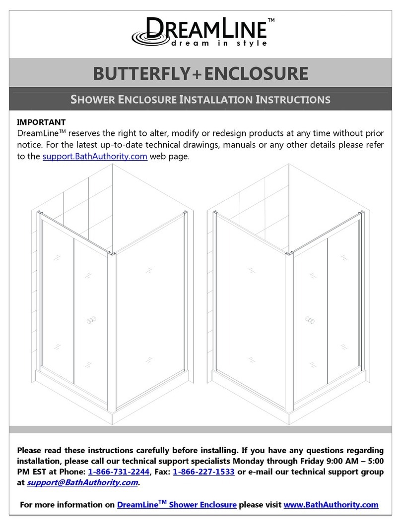
Dreamline BUTTERFLY+ENCLOSURE User manual

Dreamline

Dreamline BUTTERFLY+ENCLOSURE User manual

Dreamline Sector Service manual

Dreamline

Dreamline Sector Service manual

Dreamline AQUA SWING User manual

Dreamline

Dreamline AQUA SWING User manual

Dreamline Aqua Uno SHDR-3534586 Series User manual

Dreamline

Dreamline Aqua Uno SHDR-3534586 Series User manual

Dreamline ALLURE SHDR-4230728-01 User manual

Dreamline

Dreamline ALLURE SHDR-4230728-01 User manual

Dreamline DL-6150-04 User manual

Dreamline

Dreamline DL-6150-04 User manual

Dreamline DL-6150 User manual

Dreamline

Dreamline DL-6150 User manual

Dreamline CREST SHDR-1760760 Series User manual

Dreamline

Dreamline CREST SHDR-1760760 Series User manual

Dreamline ENCORE/BRAVO SHDR-1660580 Series User manual

Dreamline

Dreamline ENCORE/BRAVO SHDR-1660580 Series User manual

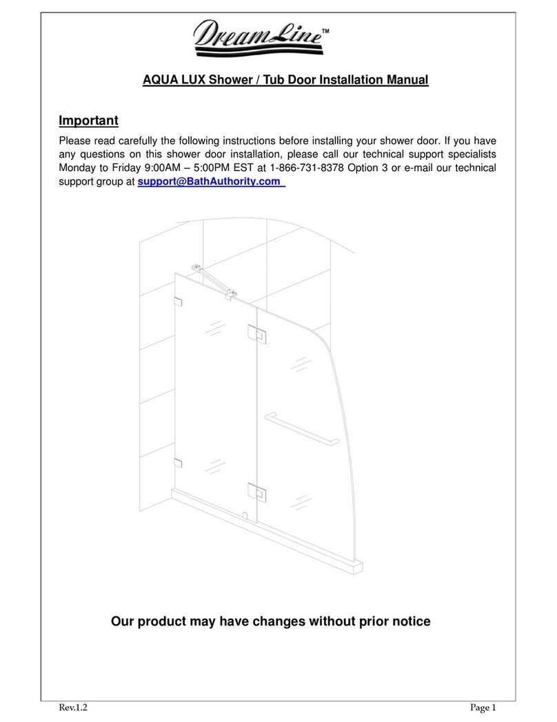
Dreamline AQUA LUX User manual

Dreamline

Dreamline AQUA LUX User manual

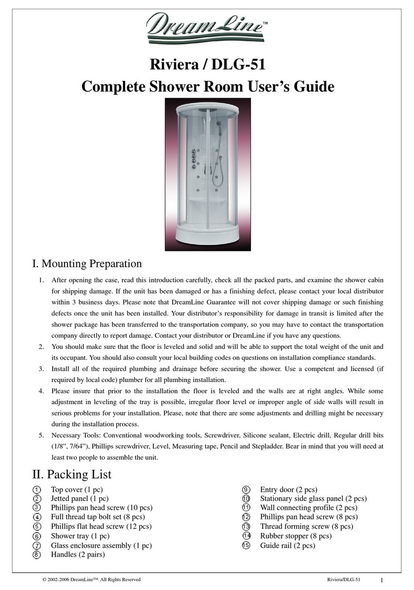
Dreamline Riviera DLG-51 User manual

Dreamline

Dreamline Riviera DLG-51 User manual

Dreamline ENIGMA-X User manual

Dreamline

Dreamline ENIGMA-X User manual

Dreamline ALLIANCE PRO ML User manual

Dreamline

Dreamline ALLIANCE PRO ML User manual

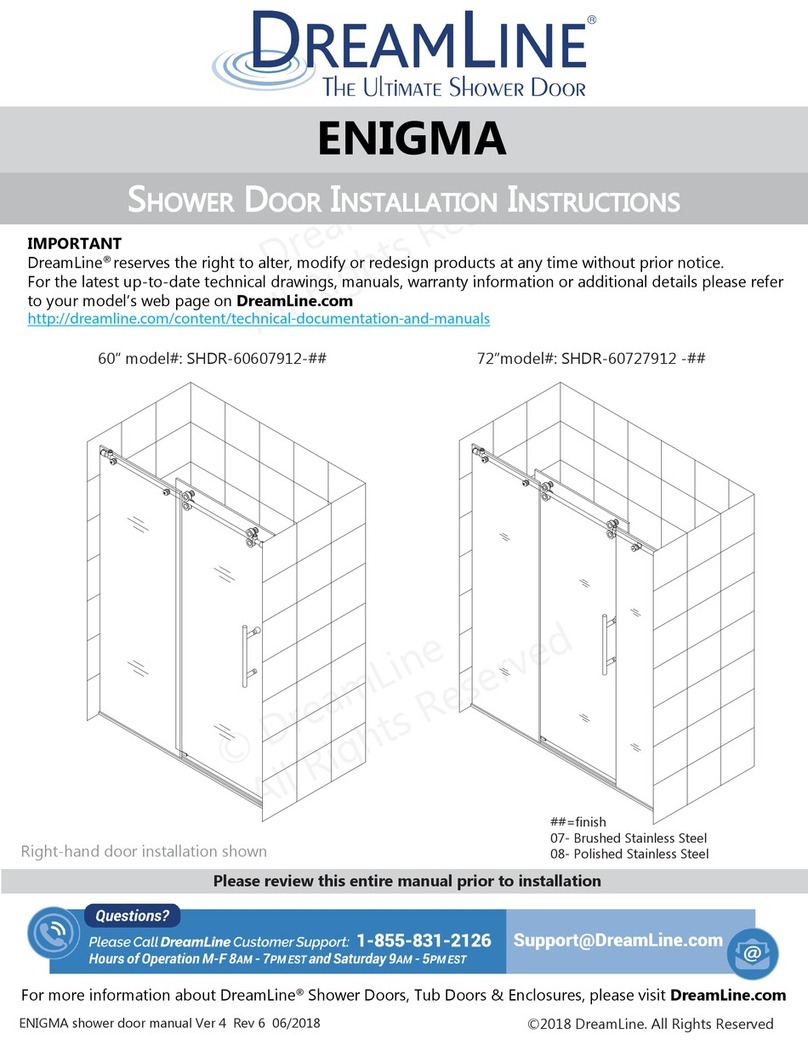
Dreamline ENIGMA SHDR-60607912 Series User manual

Dreamline

Dreamline ENIGMA SHDR-60607912 Series User manual

Dreamline ENIGMA-Z SHDR-62487610 Series User manual

Dreamline

Dreamline ENIGMA-Z SHDR-62487610 Series User manual

Dreamline SHCM-1007-00 User manual

Dreamline

Dreamline SHCM-1007-00 User manual

Popular Plumbing Product manuals by other brands

DURAVIT Inipi operating instructions

DURAVIT

DURAVIT Inipi operating instructions

Luxart SOLV SL211 instructions

Luxart

Luxart SOLV SL211 instructions

Murphy SM1 Installation and operation instructions

Murphy

Murphy SM1 Installation and operation instructions

Hans Grohe Focus 31609009 Instructions for use/assembly instructions

Hans Grohe

Hans Grohe Focus 31609009 Instructions for use/assembly instructions

Franke F5E-Therm F5ET1013 Installation and operating instructions

Franke

Franke F5E-Therm F5ET1013 Installation and operating instructions

PROCASA T1.30T Technical manual

PROCASA

PROCASA T1.30T Technical manual

WilTec CSF-500 Operation manual

WilTec

WilTec CSF-500 Operation manual

Hans Grohe Solaris 06649XX0 Specification sheet

Hans Grohe

Hans Grohe Solaris 06649XX0 Specification sheet

KWC Sliding Wall Bar K.28.H3.76.000 Specification sheet

KWC

KWC Sliding Wall Bar K.28.H3.76.000 Specification sheet

AFA Stainless AFUR3018USCOMBO owner's manual

AFA Stainless

AFA Stainless AFUR3018USCOMBO owner's manual

American Standard Hampton 2770.702 Series installation instructions

American Standard

American Standard Hampton 2770.702 Series installation instructions

Carron Phoenix RENO Fitting Instructions & Contents List

Carron Phoenix

Carron Phoenix RENO Fitting Instructions & Contents List

ProFlo PFXC5017CP installation instructions

ProFlo

ProFlo PFXC5017CP installation instructions

Kemper Full-Matic 4 Installation and operating instructions

Kemper

Kemper Full-Matic 4 Installation and operating instructions

Bristan W BATH02 C Installation instructions & user guide

Bristan

Bristan W BATH02 C Installation instructions & user guide

American Standard Cadet 2898.010 Specifications

American Standard

American Standard Cadet 2898.010 Specifications

IKEA KNYCKLAN manual

IKEA

IKEA KNYCKLAN manual

Hans Grohe Metropol Select 100 Instructions for use/assembly instructions

Hans Grohe

Hans Grohe Metropol Select 100 Instructions for use/assembly instructions

manuals.online logo
manuals.online logoBrands
  • About & Mission
  • Contact us
  • Privacy Policy
  • Terms and Conditions

Copyright 2025 Manuals.Online. All Rights Reserved.