8
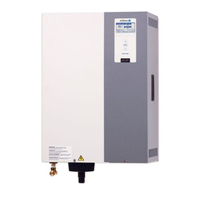
STS Humidifier
Obstruction
¾" Tubing
Funnel or Floor
Drain*
Air Gap
4" Minimum H
PIPING
Steam Supply
The heat exchanger in the STS®standard humidifier is
designed for a maximum steam pressure of 15 psi. The
steam valve, trap and strainer are shipped loose for field
installation.
Make-upWaterPiping
Either cold or hot water can be used for make-up. The
water pressure must be between 25 to 100 psi. If the
waterpressureis above 60 psiand/orwaterhammer
wouldbeobjectionable, apressurereducingvalveor
shock arrester should be installed. Even though the STS
has an inner 1" air gap, some local codes may require a
vacuum breaker in the water supply pipe.
Make-upWaterConsiderations
When non-metallic water piping is used, it must be rated
to withstand 212°F or greater temperature. If not, the final
3 feet connected to the humidifier should be metallic and
shouldnotbeinsulated.
As part of the fill valve assembly, a needle valve is
provided. It restricts the rush of cold water entering the
evaporatingchamberduring each fill cycle.The needle
valve adjusted to minimize output disruption and potential
"waterhammer"(waterpressuremustbebetween25and
100psi).
The STS Humidifier works with all water types - potable,
softenedordemineralizedmake-upwater.
Preferably this humidifier should be supplied with
softenedwater. Theprobetypelevelcontrolsystem
requireswaterconductivityof100micromhos/cm
(2 gr/gal) minimum to function and will not operate
with water treated by reverse osmosis or deionizing
process. Specially designed STS DI humidifiers are
availableforusewiththese water types.
SoftenedWater
Therearetwo majoradvantagesderivedfromusing
softenedwaterinsteadofpotable water (assuming the
untreatedsupplywater hardness isover 10 grains per
gallon):maintenance and accuracy of control.
Maintenance
The skimmer, in conjunction with softened water, is an
unbeatablecombinationforeliminatingscaleformation in
theevaporatingchamber. Severalseasonsofoperation
with no need for cleaning is normal, even with water
having up to 30 grains of dissolved minerals per gallon
priortobeingsoftened.
AccuracyofControl
Reducingthe higher skimmer quantity andeliminating the
drain/flush cycle (both of which are accomplished by the
use of softened water) improves controllability.
SoftenedWaterReducesWaterUsage
The fewer number of make-ups per unit of time and the
lesser the amount of water per make-up, the more "on
time" or actual humidifying time will occur thus improving
control accuracy. This is especially true when modulating
control of the steam input to the humidifier is used.
Figure8-1:
This piping method is recommended when obstruction
prevents dispersion tube from being continuously pitched
back to the humidifier.
OM-702 * Note: Refer to governing codes
for drain pipe size requirements.
