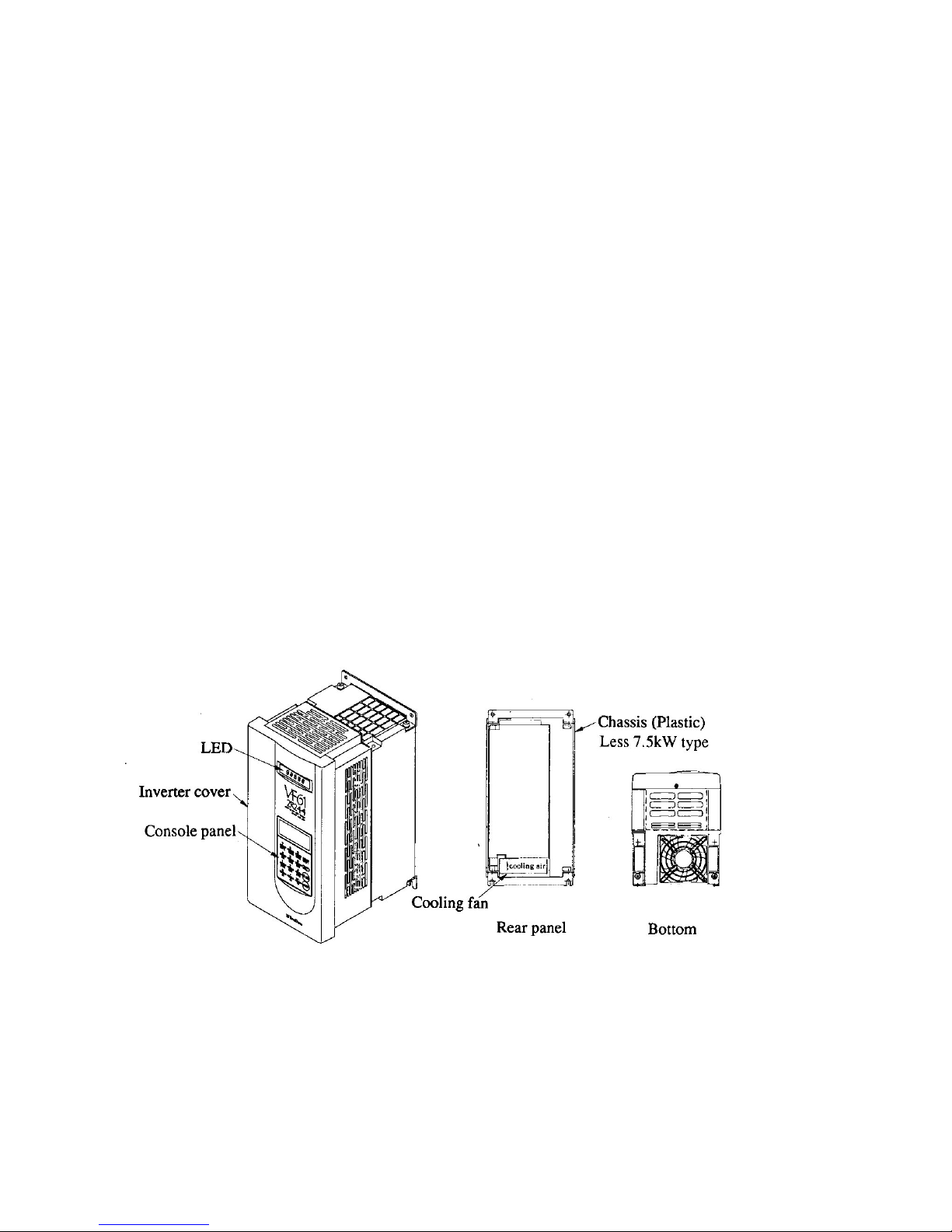
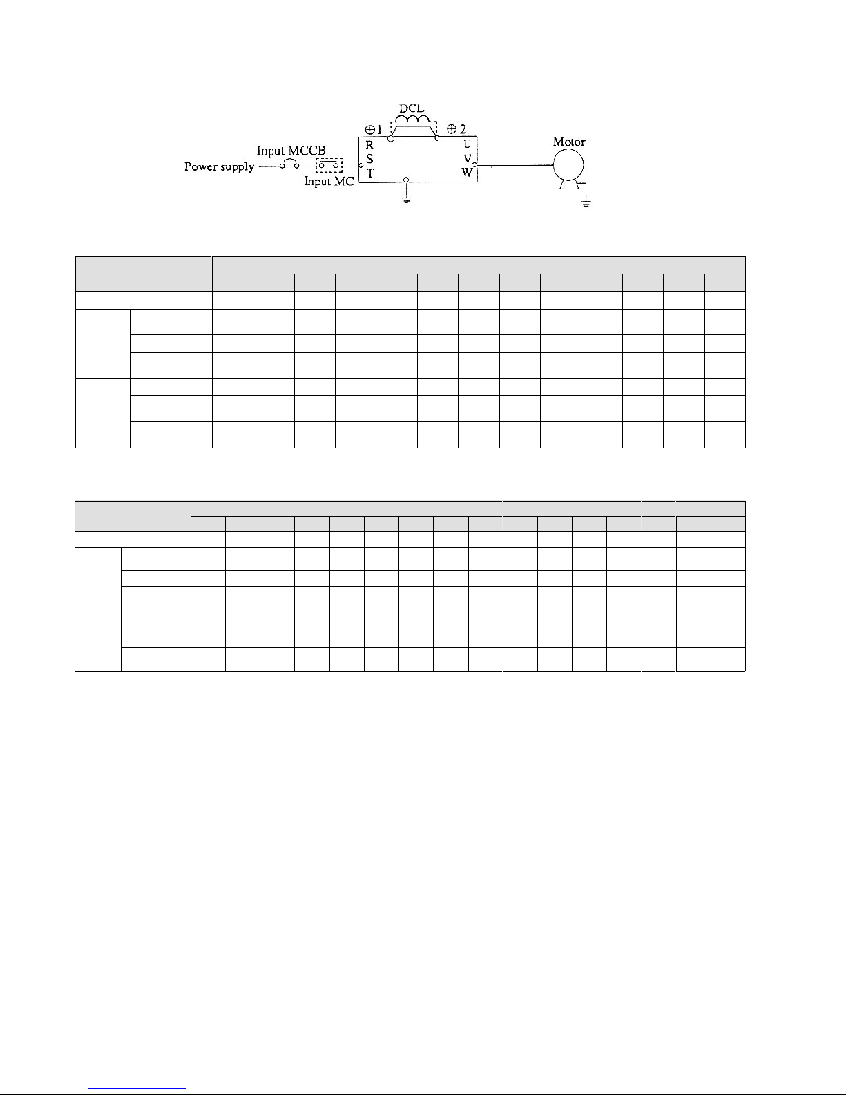
1.5 Peripheral devices and ire sizes
1.5.1 Selection of I/O devices and precautions for main circuit iring.
The follo ing sho s the I/O devices of the VF61 unit and their ire sizes.
-5-
Type VF61-__ __ __ 22
2R222 3R722 5R522 7R522 1122 1522 2222 3022 3722 4522 5522 7522 9022
Applicable motor (HP) 3 5 7.5 10 15 20 30 40 50 60 75 100 130
Peripheral
device
Input MCCB
(Note 1) 15A 20A 30A 40A 60A 60A 100A 125A 150A 225A 300A 400A 400A
Input MC (Note 2) K20 K20 K35 K50 K65 K65 K95 K125 K150 K220 K300 K400 K400
Output MC K20 K20 K25 K35 K50 K65 K95 K125 K150 K220 K300 K300 K400
Wire size
(mm²)
Input side (Note 3) 2.0 2.0 3.5 5.5 8.0 8.0 22 38 38 60 80 150 150
Output side (Note
4) 3.5 5.5 8.0 14 14 22 22 38 38 60 80 100 150
DCL terminals
(1 & 2) 2.0 2.0 3.5 5.5 8.0 14 38 38 50 80 100 150 200
200V type
Type VF61-__ __ __ 44
2R244 3R744 5R544 7R544 1144 1544 2244 3044 3744 4544 5544 7544 11044 16044 20044 25044
Applicable motor (HP) 3 5 7.5 10 15 20 30 40 50 60 75 100 150 200 250 300
Peripheral
device
Input MCCB
(Note 1) 15A 10A 15A 30A 50A 50A 75A 75A 100A 100A 125A 200A 300A 400A 500A 600A
Input MC (Note 2) K20 K20 K20 K25 K35 K50 K50 K80 K95 K100 K125 K180 K300 K400 K600 K600
Output MC K20 K20 K20 K20 K25 K50 K50 K80 K95 K95 K125 K150 K220 K300 K400 K600
Wire size
(mm²)
Input side (Note 3) 2.0 2.0 2.0 2.0 3.5 5.5 8.0 14 14 22 38 60 80 150 200 250
Output side
(Note 4) 2.0 2.0 2.0 3.5 5.5 8.0 8.0 14 22 38 38 80 150 150 150 250
DCL terminals
(1 & 2) 2.0 2.0 2.0 3.5 5.5 8.0 14 22 38 38 60 100 200 250 250 150 (x2)
400V type
Notes:
1. The values of the input MCB sho the rated currents.
(Determine the breaking capacity from the source capacity, etc.)
2. The sho n values are those of the electromagnetic contactors MS-K series made by
Mitsubishi Electric Corp.
3. The ire sizes bet een the MCB and inverter input terminals are the sizes of the KIV or RD
ires.
4. The cable length bet een the inverter and motor should be less than 30 meters. The sho n
values are those of the CV cables.
5. If the input MC is used, the interval bet een turning on and off should be more than 10
minutes.
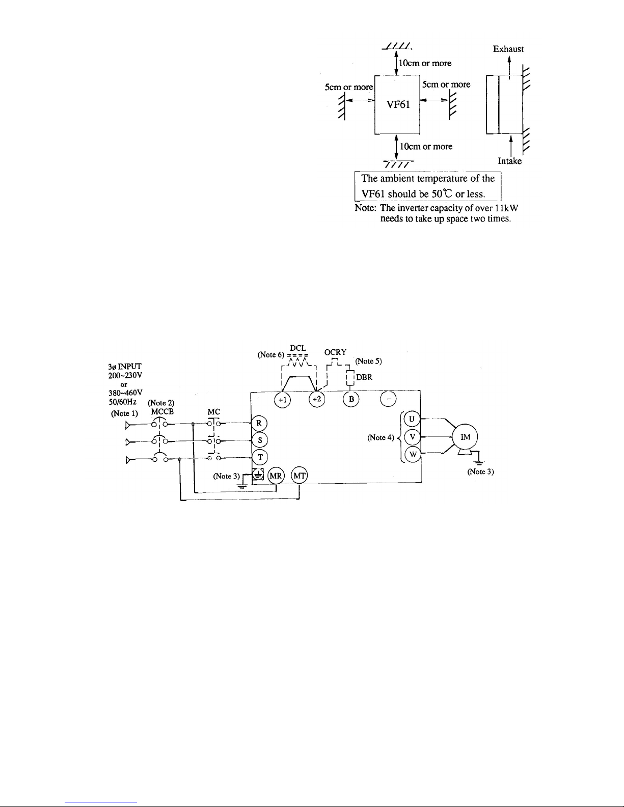
Safety Precautions
1. If the motor has a phase advancing capacitor, be sure to disconnect it. (If the inverter runs
ith the phase advancing capacitor connected, the inverter may be broken.)
2. Be sure to connect a circuit breaker (input MCB) on the inverter input side.
3. Be sure to connect the inverter and motor to ground.
(Use the exclusive grounding terminal.)