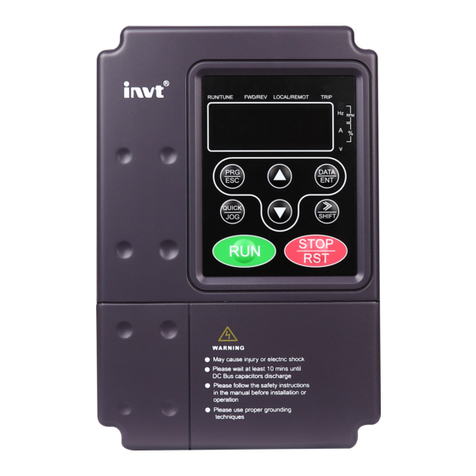
Goodrive10 Series Mini VFD Contents
-iii-
7.2.2 RTU mode...........................................................................................................87
7.3 RTU command code and communication data description.........................................90
7.3.1 Command code: 03H..........................................................................................90
7.3.2 Command code: 06H..........................................................................................92
7.3.3 Command code 08H, diagnosis..........................................................................93
7.3.4 Data address definition.......................................................................................93
7.3.5 Fieldbus ratio scale.............................................................................................97
7.3.6 Error message response ....................................................................................98
7.3.7 Read/Write operation example .........................................................................100
7.4 Common communication faults .................................................................................102
Appendix A Technical data.................................................................................................103
A.1 Derating in application...............................................................................................103
A.1.1 Capacity............................................................................................................103
A.1.2 Derating............................................................................................................103
A.2 CE .............................................................................................................................104
A.2.1 CE marking.......................................................................................................104
A.2.2 EMC compliance declaration............................................................................104
A.3 EMC regulations........................................................................................................104
A.3.1 VFDs of category C2........................................................................................105
A.3.2 VFDs of category C3........................................................................................105
Appendix B Dimension drawings ......................................................................................106
B.1 Keypad structure.......................................................................................................106
B.2 VFD chart..................................................................................................................107
Appendix C Optional peripheral accessories...................................................................108
C.1 Peripheral wiring .......................................................................................................108
C.2 Power supply ............................................................................................................109
C.3 Cable.........................................................................................................................110
C.3.1 Power cable .....................................................................................................110
C.3.2 Control cable....................................................................................................110
C.4 Breaker and electromagnetic contactor.................................................................... 111
C.5 Reactors....................................................................................................................112
C.6 Filter..........................................................................................................................113
C.6.1 C3 filter model description................................................................................113
C.6.2 C3 filter model selection...................................................................................114
C.6.3 C2 Filter model description ..............................................................................115
C.6.4 C2 filter model selection...................................................................................116
C.7 Braking system .........................................................................................................116
C.7.1 Braking unit ......................................................................................................116
C.7.2 Braking resistor selection.................................................................................116
C.7.3 Braking resistor installation ..............................................................................118
