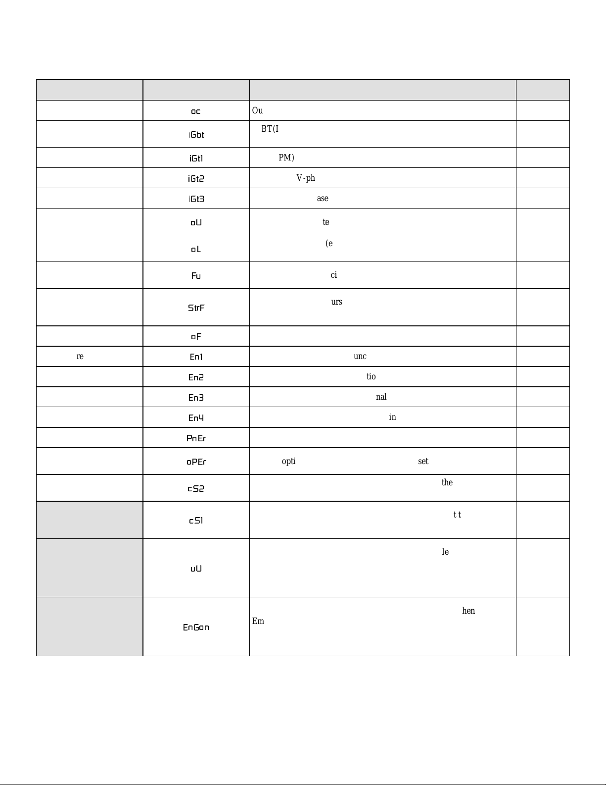
VF61 Programming Chart
Model VF61_____________________ SN:______________________
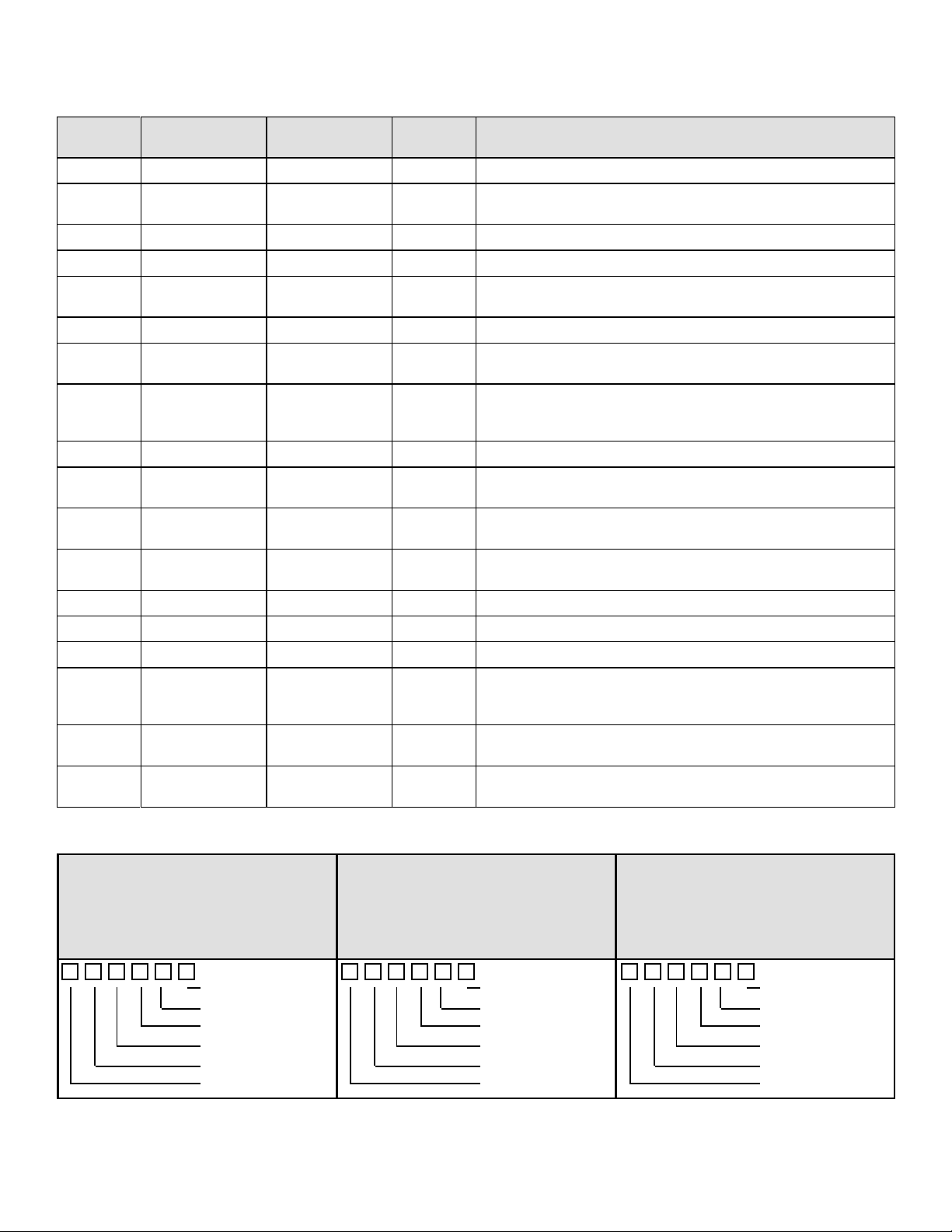
Code
No. Function Abbrev. Function setting item Unit Setting range (Setting Resolution) Change
during
operation Default User
value
52 PGM-5.Time Program operation (5) time As
set in
Code
46
0 to 1000 Possible 0
53 PGM-6 Time Program operation (6) time 0 to 1000 Possible 0
54 PGM-7 Time Program operation (7) time 0 to 1000 Possible 0
55 PGM0.Acc/Dec Program operation (0)
acceleration/deceleration selection
Sec.
Acc1/Dec1 Code # 08,09 are used (a)
Acc2/Dec2 Code # 80,81 are used (b)
Acc3/Dec3 Code # 82,83 are used (c)
Acc4/Dec4 Code # 84,85 are used (d)
Possible
(a)
56 PGM1.Acc/Dec Program operation (1)
acceleration/deceleration selection (a)
57 PGM2.Acc/Dec Program operation (2)
acceleration/deceleration selection (a)
58 PGM3.Acc/Dec Program operation (3)
acceleration/deceleration selection (a)
59 PGM4.Acc/Dec Program operation (4)
acceleration/deceleration selection (a)
60 PGM5.Acc/Dec Program operation (5)
acceleration/deceleration selection (a)
61 PGM6.Acc/Dec Program operation (6)
acceleration/deceleration selection (a)
62 PGM7.Acc/Dec Program operation (7)
acceleration/deceleration selection (a)
63 Ref.F.Sel Frequency setting operation place
selection
N/A
Dir/Rem DIR/REM Selection
(a)
Terminal Fixed at terminal (b)
Console Fixed at console
(c)
Option -1 Optional board
(d)
Option -2 For future function extension
(e)
Up/Down key arrow keys are used
Up/Down (f)
Term Multifunction input used
(g)
Impossible (a)
64 START-SW.Se Start switch operation place selection
Dir/Rem DIR/REM Selection (a)
Terminal Fixed at terminal
(b)
Console Fixed at console (c)
Option -1 Optional board (d)
Option -2 For future function extension
(e)
Impossible (a)
65 JOG-SW.Sel Jog switch operation place selection (a)
66 Term-11.Sel Terminal 11 (multi-function output)
function selection
Arrive Ref.F Set value is reached
(a)
F- Detect 1.F Frequency detection(1) (b)
F> - Detect 1.F Frequency detection (1)
(c)
F< - Detect 1.F Frequency detection (1)
(d)
F- Detect 2.F Frequency detection (2)
(e)
F> - Detect 2.F Frequency detection (2)
(f)
F< - Detect 2.F Frequency detection (2)
(g)
T> - Detect.T Torque detection (h)
OL.Pre.Alarm Overload Pre-alarm
(i)
Under Volt Insufficient voltage (j)
Reverse Now Reverse rotation in
progress (k)
Remote Now Remote selection in
progress (l)
Retrial Now Retry in progress (m)
P.time Over PGM operation is finished
(n)
Alarm Code Alarm Code
(o)
Possible
(a)
67 Term-13.Sel Terminal 13 (multi-function output)
function selection (c)
68 Term-15.Sel Terminal 15 (multi-function output)
function selection (h)
69 Term-16.Sel Terminal 16 (multi-function output)
function selection (j)
70 Detect 1.F Detected frequency (1) Hz 0 to Top.F Possible 0 Hz
71 Detect 2.F Detected frequency (2) Hz
72 DetectF.Band Frequency band detection Hz 0 to 10 Possible 0 Hz
73 Detect.Torq Torque detection % -150 to 150 Possible 100%
74 Term-24.Sel Terminal 24 (multifunction input) function
select
N/A
Preset Sel.1 Preset frequency selection
(a)
Preset Sel.2 Preset frequency selection
(b)
Preset Sel.3 Preset frequency selection
(c)
Acc/Dec Sel1 Accel./decel. selection (d)
Acc/Dec Sel2 Accel./decel. selection (e)
F.Up frequencty up (f)
F.Down frequency down (g)
Ext. Failure 1 External failure 1
(h)
Ext. Failure 2 External failure 2 (i)
Ext. Failure 3 External failure 3 (j)
Ext. Failure 4 External failure 4 (k)
DC-Brake DC brake switch (l)
F.Hold Frequency Hold (m)
P-Timer Next Go to next PGM step (n)
Emerg.Stop-A Emergency stop n.o. contact
(o)
Emerg.Stop-B Emergency stop n.c.
contact (p)
Impossible
(a)
75 Term-25.Sel Terminal 25 (multifunction input) function
select (b)
76 Term-26.Sel Terminal 26 (multifunction input) function
select (d)
77 Term-27.Sel Terminal 27 (multifunction input) function
select (h)
78 Term-28.Sel Terminal 28 (multifunction input) function
select (i)
79 Term-29.Sel Terminal 29 (multifunction input) function
select (o)
4