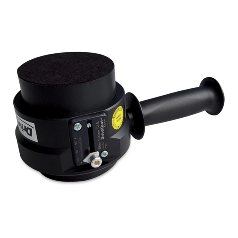
DriveTest BIA 600 User manual

BIA 600
Pinch Force Meter for Railway Doors
(EN14752)
Manual

Drive Test GmbH Munich Manual BIA600 Page 1 of 56
Version 5.2 Archive: Stamm_BIA600_EN_V5.2.docx
Inhalt
1. GENERAL..................................................................................................5
1.1 PURPOSE OF USE....................................................................................5
1.2 PROPER USE............................................................................................5
1.3 OLD DEVICES ...........................................................................................5
1.4 BATTERIES AND RECHARGEBLE BATTERIES.......................................5
1.5 TRANSPORT .............................................................................................5
2. SYSTEM ARCHITECTURE........................................................................6
2.1 TETHERED................................................................................................6
2.1.1 Sensor - SEB2............................................................................................6
2.1.2 Sensor - SEB2 - RS232 –Windows-PC (PinchPilot)...................................6
2.1.3 Sensor - SEB2.2 - USB –Windows-PC (PinchPilot)...................................6
2.1.4 Sensor - SEB2.2 - USB –Windows-PC (DLL) ............................................6
2.2 WIRELESS.................................................................................................6
2.2.1 Sensor-BT –Bluetooth –Android Endgerät (ForceMeter)...........................6
2.2.2 Sensor-BT –Bluetooth –Windows-PC (PinchPilot)....................................6
3. STARTING UP ...........................................................................................7
3.1 BIA600-(TETHERED).................................................................................7
3.1.1 Determining completeness .........................................................................7
3.1.2 Function test...............................................................................................8
3.2 BIA600 BT (WIRELESS).............................................................................8
3.2.1 Determining completeness .........................................................................8
3.2.2 Function test (PinchPilot –PC)...................................................................8
3.2.3 Function test (ForceMeter App –tablet)......................................................8
3.3 PLACING OUT OF OPERATION................................................................8
4. PINCH FORCE SENSOR...........................................................................9
4.1 BASIC CONSTRUCTION...........................................................................9
4.2 SPACER...................................................................................................10
4.3 SENSOR DATA........................................................................................10
4.4 MAINTENANCE........................................................................................10
5. CALIBRATION.........................................................................................11
6. DECLARATION OF CE - CONFORMITY.................................................11
7. DISPLAY UNIT SEB2 / SEB2.2 ...............................................................12
7.1 DISPLAY, OPERATING ELEMENTS........................................................12
7.2 MEMORY CAPACITY...............................................................................13
7.3 DISPLAY UNIT EVALUATION..................................................................13
7.4 DATA TRANSFER....................................................................................14
7.5 BASIC SETTINGS....................................................................................14

Drive Test GmbH Munich Manual BIA600 Page 2 of 56
Version 5.2 Archive: Stamm_BIA600_EN_V5.2.docx
7.5.1 Erase memory..........................................................................................14
7.5.2 Peak force limit.........................................................................................14
7.5.3 Mode of measurement..............................................................................15
7.6 ERROR MESSAGES................................................................................15
7.7 DISPLAY UNIT MAINTENANCE ..............................................................15
7.8 BATTERY SEB2.......................................................................................16
7.8.1 Battery load state......................................................................................16
7.8.2 Transportation ..........................................................................................16
7.9 BATTERY SEB2.2....................................................................................17
7.9.1 Battery loading..........................................................................................17
7.9.2 Battery load state......................................................................................17
7.9.3 Transportation ..........................................................................................18
7.9.4 Disposal....................................................................................................18
7.9.5 Safety data sheet for Lithium-Polymer batteries........................................18
7.10 SEB2.2 OPTION: ANALOG INTERFACE 0509........................................19
7.10.1 Turn off/ on...............................................................................................19
7.10.2 Settings ....................................................................................................20
7.11 MEASURING SEB2 / SEB2.2...................................................................21
7.11.1 Preparation...............................................................................................21
7.11.2 Turn on display unit, set limit ....................................................................21
7.11.3 Measuring process ...................................................................................21
7.11.4 Load measured data into PC (upload) ......................................................22
7.11.5 Enter measurement properties..................................................................22
7.11.6 Print measurement report.........................................................................22
7.11.7 Short operating instructions......................................................................23
8. PC SOFTWARE PINCHPILOT.................................................................24
8.1 INSTALLATION........................................................................................24
8.1.1 System requirements................................................................................24
8.1.2 Installation steps.......................................................................................24
8.1.3 Language .................................................................................................24
8.1.4 Interface setting related to display unit......................................................25
8.1.5 Software updates......................................................................................26
8.1.6 Uninstalling software.................................................................................26
8.2 END USER LICENSE AGREEMENT........................................................26
8.3 GENERAL OPERATING STANDARD......................................................26
8.4 MAIN MENU.............................................................................................27
8.5 MEASUREMENT DATA ...........................................................................27
8.5.1 File name..................................................................................................27
8.5.2 Location of files.........................................................................................27
8.5.3 Properties.................................................................................................28
8.5.4 Details ......................................................................................................28
8.5.5 Data administration...................................................................................28
8.5.6 Single/ double/ triple/ quintuple measurement ..........................................29
8.5.7 Export.......................................................................................................29
8.5.8 Print..........................................................................................................29
8.6 PINCHPILOT SETTINGS .........................................................................30
8.6.1 Extras/ Options.........................................................................................30
8.6.2 Extras/ Settings ........................................................................................31

Drive Test GmbH Munich Manual BIA600 Page 3 of 56
Version 5.2 Archive: Stamm_BIA600_EN_V5.2.docx
8.6.3 Sensor/ Configuration...............................................................................32
8.6.4 Operating bars..........................................................................................34
8.7 MEASURING WITH PINCHPILOT............................................................35
8.7.1 Normal operation......................................................................................35
8.7.2 Controlled by PinchPilot............................................................................35
8.8 SOFTWARE MAINTENANCE...................................................................36
8.9 SOFTWARE PLUG-INS............................................................................36
8.10 SEQUENCE OF MEASUREMENTS.........................................................37
8.10.1 Templates.................................................................................................38
8.10.2 Details to work with sequences.................................................................38
8.10.3 Options of sequences...............................................................................39
8.11 CHANGE OF GUIDELINES......................................................................40
8.12 SOFTWARE EVALUATION......................................................................41
9. GUIDELINES, STANDARDS....................................................................42
9.1 GENERAL DEFINITION OF TERMS........................................................43
9.2 EN14752:2015..........................................................................................44
9.2.1 Test methods............................................................................................44
9.2.2 Requirements...........................................................................................44
9.2.3 Spacer detection.......................................................................................46
9.2.4 Evaluation display unit..............................................................................46
9.2.5 Evaluation PC-software PinchPilot............................................................46
9.3 EN14752:2019..........................................................................................46
9.4 EN14752:2022..........................................................................................46
9.5 EN14752:2005..........................................................................................47
9.5.1 Sensor width.............................................................................................47
9.5.2 Test methods............................................................................................47
9.5.3 Requirements...........................................................................................47
9.5.4 Evaluation display unit..............................................................................48
9.5.5 Evaluation PinchPilot................................................................................48
9.6 §35E, ABS. 5 STVZO ...............................................................................49
9.6.1 Test methods............................................................................................49
9.6.2 Requirements...........................................................................................49
9.6.3 Evaluation display unit..............................................................................50
9.6.4 Evaluation PinchPilot................................................................................50
9.7 EN14752-DB ............................................................................................51
10. TECHNICAL DATA..................................................................................52
10.1 SENSOR ..................................................................................................52
10.2 FORCE MEASUREMENT ........................................................................52
10.3 POWER SUPPLY.....................................................................................52
10.3.1 SEB2........................................................................................................52
10.3.2 SEB2.2.....................................................................................................52
10.3.3 SEB2.2B...................................................................................................52
10.4 ENVIRONMENT.......................................................................................52
10.5 ANALOG INTERFACE (OPTIONAL, ONLY FOR SEB2.2) .......................53

Drive Test GmbH Munich Manual BIA600 Page 4 of 56
Version 5.2 Archive: Stamm_BIA600_EN_V5.2.docx
11. GUARANTEE...........................................................................................54
12. CONTACT INFORMATION......................................................................54
13. APPENDIX...............................................................................................55
13.1 ERROR MESSAGES DISPLAY UNIT.......................................................55

Drive Test GmbH Munich Manual BIA600 Page 5 of 56
Version 5.2 Archive: Stamm_BIA600_EN_V5.2.docx
1. GENERAL
1.1 PURPOSE OF USE
The purpose of use of the Force Meter BIA600 is to measure the closing force of power
operated doors and evaluate the measured results with respect to the requirements of
applicable standards (refer to chapter “Standards”).
1.2 PROPER USE
Only use the device as described in this manual. Any other usage will be deemed as not in
accordance with the instructions and may lead to damage of property or even persons. The
manufacturer accepts no liability for damage caused by improper use.
1.3 OLD DEVICES
Old devices must not be disposed with household waste. They should be disposed in a local
recycling centre.
1.4 BATTERIES AND RECHARGEBLE BATTERIES
Every user is required to bring all batteries to local recycling centres.
1.5 TRANSPORT
For any transport of the instrument the transport case should be used.

Drive Test GmbH Munich Manual BIA600 Page 6 of 56
Version 5.2 Archive: Stamm_BIA600_EN_V5.2.docx
2. SYSTEM ARCHITECTURE
2.1 TETHERED
2.1.1 Sensor - SEB2
2.1.2 Sensor - SEB2 - RS232 –Windows-PC (PinchPilot)
2.1.3 Sensor - SEB2.2 - USB –Windows-PC (PinchPilot)
2.1.4 Sensor - SEB2.2 - USB –Windows-PC (DLL)
2.2 WIRELESS
2.2.1 Sensor-BT –Bluetooth –Android Endgerät (ForceMeter)
2.2.2 Sensor-BT –Bluetooth –Windows-PC (PinchPilot)

Drive Test GmbH Munich Manual BIA600 Page 7 of 56
Version 5.2 Archive: Stamm_BIA600_EN_V5.2.docx
3. STARTING UP
3.1 BIA600-(TETHERED)
3.1.1 Determining completeness
Sensor BIA600
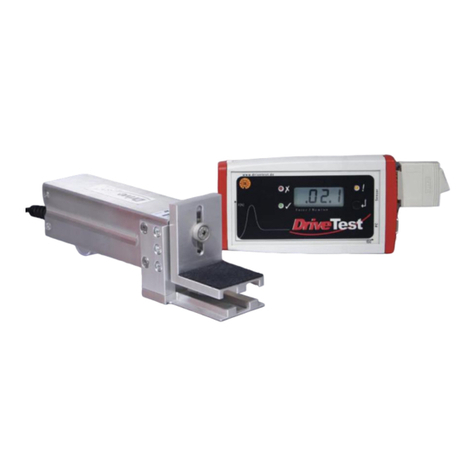
Display unit SEB2 or SEB2.2
USB-cable, USB charger (SEB2.2)
PinchPilot-software (USB Stick)
Set of spacers (4 pieces)
Manual, calibration certificate (placed in the cover of the transport case)
Transport case
Display Unit
Sensor BIA600
Spacer No. 1
Spacer No. 2
Spacer No. 3
Spacer
No. 4

Drive Test GmbH Munich Manual BIA600 Page 8 of 56
Version 5.2 Archive: Stamm_BIA600_EN_V5.2.docx
3.1.2 Function test
Load display unit battery via USB charger
connect sensor to display unit,
turn on the display unit by briefly pressing the display unit push button,
after initialisation start a measurement by pressing the push button of the display unit,
apply/remove load to sensor, force is displayed
3.2 BIA600 BT (WIRELESS)
3.2.1 Determining completeness
sensor BIA600-BT
USB-cable, USB charger
PinchPilot-software (USB Stick)
set of spacers (4 pieces)
calibration certificate (placed in the cover of the transport case)
transport case
3.2.2 Function test (PinchPilot –PC)
Load sensor battery via USB charger
turn on sensor
connect sensor to PC via Bluetooth (refer chapter “PinchPilot)
install PC-software PinchPilot, connect PinchPilot to sensor (refer chapter “PinchPilot)
start a measurement via PinchPilot (sensor/Measure/start button)
apply/remove a load to sensor, measured force is displayed
3.2.3 Function test (ForceMeter App –tablet)
Load sensor battery via USB charger
Install ForceMeter App on Tablet (refer to chapter ForceMeter-App)
start a measurement via ForceMeter App
apply/remove a load to sensor; measured force is displayed
3.3 PLACING OUT OF OPERATION
When the instrument will not be used for a longer period of time, please regard these
measures:
Check if data to be used is still stored in the display unit (if so, upload data)
SEB2: remove battery; SEB2.2: Charge battery
The instrument should be stored in a dry environment within the limits of storage
temperature (refer to “Technical Data”).

Drive Test GmbH Munich Manual BIA600 Page 9 of 56
Version 5.2 Archive: Stamm_BIA600_EN_V5.2.docx
4. PINCH FORCE SENSOR
4.1 BASIC CONSTRUCTION
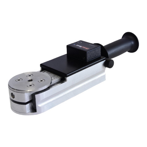
The instrument consists of a right and a left force initiation area of 100x100 mm.
The link between the two parts is performed by a leaf spring system including a strain gauge
Mechanical dimensions in mm
100
90

Drive Test GmbH Munich Manual BIA600 Page 10 of 56
Version 5.2 Archive: Stamm_BIA600_EN_V5.2.docx
4.2 SPACER
The EN14752:2015 standard requires to measure the closing force at different apertures. The
BIA600 spacer set facilitates these measurements.
The spacers can be mounted onto the BIA600 sensor without any tool. The applied spacers
are automatically detected. This information is added to the measurement properties thus
enabling the software to calculate the sensor width and applying the appropriate limit for
compliance check.
The spacer set ensures fast and easy measurements. Confusions concerning opening width
are avoided.
4.3 SENSOR DATA
Important sensor specific data is stored in a non-volatile memory (EEPROM), situated in the
sensors connector (15-pol. Sub-D). The sensor data in detail is:
Force adjustment data,
Sensor-ID, Version, Serial-No. ,
Guidelines category,
Date of last calibration,
Number of measurements.
4.4 MAINTENANCE
The instrument has to be protected from moisture, dirt and solar radiation. It is designed to
withstand normal handling and transportation, nevertheless excessive shock or load
(>1000 N) can damage it and should be avoided. Most of the parts are fabricated from
durable aluminium or POM. To clean the device, wipe it with a damp cloth. Avoid contact to
acids and thinner.

Drive Test GmbH Munich Manual BIA600 Page 11 of 56
Version 5.2 Archive: Stamm_BIA600_EN_V5.2.docx
5. CALIBRATION
Drive Test meters are very precise instruments, but can be easily damaged by inappropriate
treatment like dropping etc. .
To ensure proper function, calibration in intervals of one year is recommended. The
calibration date and state appear on the report.
6. DECLARATION OF CE - CONFORMITY
We,
Drive Test GmbH
Adi-Maislinger-Str. 9
81373 Muenchen
Germany
declare that the Pinch Force Meter:
- BIA600
meet the intend of the applicable EC directives:
2006/42/EC
Machinery Directive
2006/95/EC
Low Voltage Directive
München, 18.08.2015
Wolfgang Schabel, CEO

Drive Test GmbH Munich Manual BIA600 Page 12 of 56
Version 5.2 Archive: Stamm_BIA600_EN_V5.2.docx
7. DISPLAY UNIT SEB2 / SEB2.2
The display unit is used to display, evaluate and store the measurements. A short guide to
measure is attached to the back of the display unit.
The functions of the display unit are:
Controlling measurements
Storing measurements
Display measured peak force and evaluate measurements
Upload measured data to a PC
7.1 DISPLAY, OPERATING ELEMENTS
The display unit elements are three LEDs and a 3.5 digits LCD display.
The meanings of the LEDs are:
!
State LED
Result LED: not OK
Result LED: OK
There is one button to operate the display unit:
Operating button

Drive Test GmbH Munich Manual BIA600 Page 13 of 56
Version 5.2 Archive: Stamm_BIA600_EN_V5.2.docx
The function of the operating button is different, according to the state of the display unit. In
the “off” state the display unit can be turned on. In the “on” state the display unit can be
turned off by pressing the button longer than two seconds.
By a short push on the operating button (with a connected sensor) a measurement is started.
Afterwards the result can be stored by a short push, or by a long push being rejected. When
not in measurement state the SEB2 can be switched off by a long push on the operating
button.
After initialisation, the display unit will enter the ready state. The state LED flashes slowly.
The number of the next free memory location is displayed.
In case of an expired calibration period (> 15 months), the red result LED flashes (refer to
chapter “General details/ Calibration”).
Display of the next free memory no.
Type of measurement
Memory
no.
Measurement no.
Display
Single measurement
1
1
.01.
Double measurement
1
1
.01.1
Double measurement
1
2
.01.2
Triple measurement
1
1
.01.1
Triple measurement
1
2
.01.2
Triple measurement
1
3
.01.3
Quintuple measurement
1
1
.01.1
Quintuple measurement
1
2
.01.2
Quintuple measurement
1
3
.01.3
Quintuple measurement
1
4
.01.4
Quintuple measurement
1
5
.01.5
7.2 MEMORY CAPACITY
Measurement data is stored in a compressed format. The capacity of the memory is
app. 80 single or triple measurements.
7.3 DISPLAY UNIT EVALUATION
The peak force over the entire measurement period is displayed. This value is compared with
the permissible peak force. Additionally, the pulse duration is compared with the actual limit
value. Depending on this comparison, the red orgreen LED willbe lit up. A complete evaluation
is performed by the PC-software PinchPilot.

Drive Test GmbH Munich Manual BIA600 Page 14 of 56
Version 5.2 Archive: Stamm_BIA600_EN_V5.2.docx
7.4 DATA TRANSFER
The display unit has to be connected to the USB port and is turned on by pressing
briefly on the operating button. The data transfer is controlled by the PC software
PinchPilot.
The display unit and the software do normally detect each other (Plug and Play). If not,
please connect the USB adapter and check the available connections in the device manager
(“Control panel” on your PC).
Open the Windows Device Manager
Open “Ports.(COM & LPT)”
Select COM-port (USB plug is displayed as virtual COM port)
For initial setting procedure refer to chapter “Software PinchPilot/ Installation/ Interface
setting related to display unit”.
7.5 BASIC SETTINGS
Basically all settings may be set within the PC-software PinchPilot (refer chapter “PinchPilot/
Sensor/ Configuration) . Nevertheless, some settings may be modified directly at the display
unit SEB2 without connecting the PinchPilot-PC.
7.5.1 Erase memory
To erase all stored data in the display unit, make sure the display unit is turned off. Now
press the operating button for a time period longer than two seconds. This will turn the
display unit on, and for a short time period three dashes (- - -) will appear, indicating that all
data is erased. After this action, the next available memory no. will be 01.
7.5.2 Peak force limit
Precondition: limit value selectable (PinchPilot: sensor/configuration/extended).
Depending on the guideline different peak force limits may be applied. Up to three different
limits are available. It makes sense to set the applicable peak force before measuring in order
to simplify later evaluations.
Settings:
(requires activation via PinchPilot: Sensor/Configuration/extended: O Limit value selectable)
SEB2.2: After turning on the actual battery status is displayed for 2s. Press during this
phase the button again for 2s. Then the actual limit is displayed for 2s.
SEB2: After turning on the actual limit is displayed for 2s.
Press the operating button briefly to switch to the next limit value.
(Peak force limit setting will be omitted in case of guidelines with just one limit).

Drive Test GmbH Munich Manual BIA600 Page 15 of 56
Version 5.2 Archive: Stamm_BIA600_EN_V5.2.docx
7.5.3 Mode of measurement
Precondition: selectable mode (PinchPilot: sensor/configuration/extended).
Depending on the standard, a single, a dual or a triple measurement is required. An
additional setting is the option “auto sequence”. In this case, the next measurement is started
automatically. The user can fully concentrate on the closing system to be tested.
Settings:
(requires activation via PinchPilot: Sensor/Configuration/extended: O selectable mode)
SEB2.2: After turning on the actual battery status is displayed for 2s. Press during this
phase the button again for 2s. Then the actual limit is displayed for 2s.
SEB2: After turning on the actual limit is displayed for 2s.
Press operating button again for two seconds. The actual mode is displayed for two
seconds.
Press briefly to switch to the next mode and repeat until the desired mode is set.
Display
Meaning
1
Single measurement
+1
Single measurement with auto sequence
permanent restart, display of last peak force, no graphic data acquisition
2
Dual measurement
+2
Dual measurement with auto sequence
automatic start of second measurement
3
Triple measurement
3+
Triple measurement with auto sequence
automatic start of second and third measurement
5
Quintuple measurement
5+
Quintuple measurement with auto sequence
automatic start of second, third, fourth and fifth measurement
7.6 ERROR MESSAGES
If the display unit detects a malfunction, an error message is displayed (E:xx). The meaning
of the two digits error no. is explained in the appendix table “Error messages display unit”.
7.7 DISPLAY UNIT MAINTENANCE
The display unit does not need any special maintenance. It should not be exposed to direct
sunlight for a longer time. Working range is temperature 0° to +40° Celsius at maximum 90%
humidity non-condensing. When dirty, clean it carefully with a soft, damp cloth. Avoid contact
to acids and thinner. For more information see section “Technical data”.

Drive Test GmbH Munich Manual BIA600 Page 16 of 56
Version 5.2 Archive: Stamm_BIA600_EN_V5.2.docx
7.8 BATTERY SEB2
The SEB2 is equipped with a non rechargeable Alkaline battery.
7.8.1 Battery load state
When the message „BAT“ is permanently indicated on the LCD display, it is time for a battery
exchange. A special capacitor ensures that no measurement data will be lost and the real
time clock does not stop running.
Change the battery by removing the cap on left hand side of the display unit. Pressing the
two locking buttons does this.
Battery change
Caution! Do not tilt one of the caps sideways; this can damage the locking element.
7.8.2 Transportation
The SEB 2 contains an alkaline battery cell. These are not classified as dangerous goods in
transportation.

Drive Test GmbH Munich Manual BIA600 Page 17 of 56
Version 5.2 Archive: Stamm_BIA600_EN_V5.2.docx
7.9 BATTERY SEB2.2
The display unit SEB2.2 is equipped with a rechargeable Lithium-Polymer battery.
7.9.1 Battery loading
The battery is loaded via USB interface. Loading source can be either a PC or a USB
charging device. The time to charge the battery from 0% to 100% is about four hours.
7.9.2 Battery load state
During initialization (turning on display unit SEB2.2) with sensor connected and USB
disconnected the battery’s load state is displayed in percent (0% … 100%) for two seconds
During operation, the battery’s state is permanently examined. If the load state falls below
30%, the display’s BAT indicator is activated (see Fig. 3.3).

Drive Test GmbH Munich Manual BIA600 Page 18 of 56
Version 5.2 Archive: Stamm_BIA600_EN_V5.2.docx
7.9.3 Transportation
The display unit SEB 2.2 contains a Lithium-Polymer battery cell. These are classified as
dangerous goods in transportation. As this is a build-in battery cell please follow guidelines
UN3481 and respect your local law.
Consider the package labelling requirements therefore by putting a label outside on the
package looking like Figure 3.4. The size should be min. 120mm x 110mm, on small boxes
(where it does not fit on one side) it can be 105mm x 74mm. It has to be printed in colour.
Please find further information on our website (refer chapter “Contact information”).
7.9.4 Disposal
It is not allowed to dispose Lithium-Polymer battery cells or equipment with a build-in battery
cell in standard garbage, and also electronic devices in general require a special handling for
disposal.
You can resend the complete display unit to us for disposal, but please contact us first (see
“Contact information”). You are free to follow your local rules for local disposal or contact the
battery’s supplier on his website www.dynamis-batterien.de for a local agent which is able to
help you with the disposal.
7.9.5 Safety data sheet for Lithium-Polymer batteries
Please find the battery cell’s safety notice on the website of our battery supplier
www.dynamis-batterien.de.

Drive Test GmbH Munich Manual BIA600 Page 19 of 56
Version 5.2 Archive: Stamm_BIA600_EN_V5.2.docx
7.10 SEB2.2 OPTION: ANALOG INTERFACE 0509
The optional analog interface 0509 is available only for SEB2.2 display unit.
Features of the analog interface 0509 are:
BNC output connector, isolated from display unit SEB2.2
Output of analog value during measurement
Range: 0 –4000 mV
Refresh rate according to sensor used (250 or 500 S/s)
Adjustable force range: 250N, 500N, 1000N, 2000N
7.10.1 Turn off/ on
To turn on and turn off the analog interface, please follow these steps:
Turn on: Move the sliding switch to the left side (towards the BNC connector).
Turn off: Move the sliding switch to the right side.
In order to reduce current consumption, turn the analog interface off when not used.
Table of contents
Other DriveTest Measuring Instrument manuals