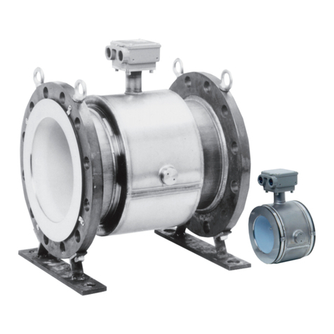
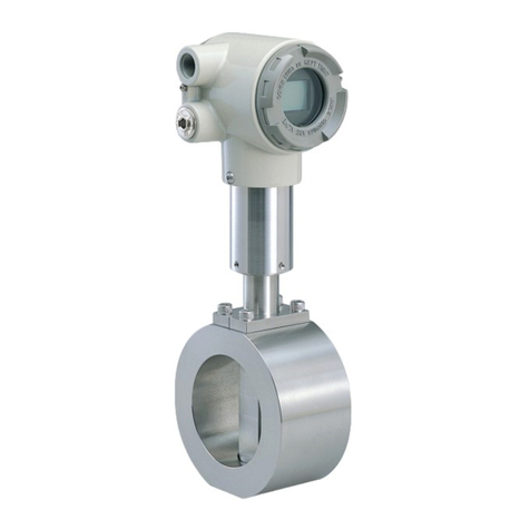
Azbil MCB10A User manual

Electromagnetic Flowmeter
for Water Measurement
Model: MCB10A
User’s Manual
CM2-MCB100-2001
3rd edition

Copyright, Notices and Trademarks
© 2004-2020 Azbil Corporation All Rights Reserved.
While this information is presented in good faith and believed to be ac-
curate, Azbil Corporation disclaims the implied warranties of merchant-
ability and tness for a particular purpose and makes no express war-
ranties except as may be stated in its written agreement with and for its
customer.
In no event is Azbil Corporation liable to anyone for any indirect, special
or consequential damages. This information and specications in this
document are subject to change without notice.

Model MCB10A i
Preface
Thank you for purchasing our electromagnetic owmeter. The model MCB is a
owmeter dedicated to water ow measurement and was developed applying the
basic principle of electromagnetic ow measurement to be an inexpensive, easy-to-
use instrument.

Preface Azbil Corporation
ii Model MCB10A
Unpacking, product checking and storage
Unpacking
This instrument is a precision instrument. When unpacking, handle it with care to
prevent accidents or damage. Check that the following items are contained:
• MCB main unit, standard accessories and SETTING DATA sheet
Verifying the specications
Specications are written on the nameplate of the main unit. Referring to
Specication sheet, check that these are consistent with your specications. Check the
following items, in particular:
(Main unit)
• Detector bore diameter
• Flange rating
Inquiries
If you have any questions regarding the specications, contact the nearest Azbil
Corporation oce or Azbil Corporation representative service oces. When making
an inquiry, be sure to provide the MODEL NO. and PRODUCT NO.
Storage precautions
When storing this instrument before use, observe the following precautions:
• Store it indoors and at room temperature (25°C, 77°F) and humidity (65% RH),
safely away from vibration or shock.
• Store it in its packed and shipped state.
When storing this instrument after use, follow these steps:
1. Rinse the inside of the detector with water to remove the adhering measured uid
and dry o the water.
2. Tighten the display cover and waterproof gland to keep out moisture.
3. Replace the device in its original packing.
4. Store it indoors at room temperature and humidity, safely away from vibration and
shock.

Azbil Corporation Preface
Model MCB10A iii
Safety
About this manual
This manual contains information and warnings that must be observed to keep the
model MCB10A electromagnetic owmeter operating safely. Correct installation,
correct operation and regular maintenance are essential to ensure safety while using
this device.
For the correct and safe use of this electromagnetic owmeter, it is essential that
both operating and service personnel follow generally accepted safety procedures in
addition to the safety precautions specied in this manual.
The following symbols are used in this manual to alert you to possible hazards:
WARNING
Denotes a potentially hazardous situation which, if not avoided, could result in
death or serious injury.
CAUTION
Failure to observe these precautions may produce dangerous conditions that could
result in operator injury or in physical damage to the device.
Safety message
Carefully read this section before installing or operating this device.
WARNING
ELECTRIC SHOCK HAZARD! Turn the power supply OFF before opening the
converter cover.
WARNING
This detector is heavy. Dropping it could cause personal injury or damage to the
device.
WARNING
Before removing the unit, make sure that there is no residual liquid or pressure
inside the piping and the detector to avoid personal injury or damage to the unit.

Preface Azbil Corporation
iv Model MCB10A
CAUTION
Switch the control equipment to manual control before terminating electromagnetic
owmeter operation and shutting o the output to the control equipment. This
action prevents the power shut-o from directly aecting the control equipment.
CAUTION
Install the electromagnetic owmeter in a location with an ambient temperature
of 0 to 50°C (32 to 122°F) and an ambient humidity of 5 to 85% RH (no
condensation) to prevent equipment malfunction or output errors.
CAUTION
Do not install the electromagnetic owmeter near high-current power lines, motors
or transformers to prevent damage from electromagnetic induction, which can
cause equipment malfunction or output errors.
CAUTION
Do not install the electromagnetic owmeter in a location subject to direct sunlight,
wind, rain, severe vibration, or in a highly corrosive atmosphere. The converter and
detector can be damaged. The electromagnetic owmeter is for indoor use only.
CAUTION
Be sure to ground the welding power transformer when welding near the
electromagnetic owmeter to avoid output errors.
CAUTION
DO NOT use the electromagnetic owmeter to ground a welder. It can damage the
electromagnetic owmeter.
CAUTION
The detector must be grounded (grounding resistance is < 100 W) to avoid output
uctuation, zero point instability or output drift.

Azbil Corporation Preface
Model MCB10A v
CAUTION
Measurable process uids of the electromagnetic owmeter are chilled water,
water with glycol, water and hot water. No corrosive uid and no abrasive uid
is applicable. Corrosive uid and abrasive uid can damage the electromagnetic
owmeter.
CAUTION
If the pipe is not lled, output errors will occur.
CAUTION
Do not rotate the unit more than 180° (one half rotation). Any further rotation can
disconnect wiring.
After removing the screws, do not pull on the converter. You can break the lead
wire.
When you move the converter, make sure the O-ring remains in the groove to
insure an air-tight seal when the unit is reassembled.
CAUTION
Before installing the detector, make sure any foreign matter is ushed from
the interior passage of the detector. Residual foreign matter could cause output
uctuations.
Do not touch the electrodes or allow oil or fat to come into contact with them to
avoid output uctuations.
Align the direction mark on the detector in the direction of the liquid ow.
Misalignment can result in a negative output.
CAUTION
The correct fastening torque must be used to prevent leakage. To avoid damage to
the detector, do not exceed the listed fastening torque.
CAUTION
Before installing the detector, make sure that the pipe is exactly straight and
centered. Any irregularity could cause leakage or other hazards.

Preface Azbil Corporation
vi Model MCB10A
CAUTION
Never attempt to force the detector between two ange if the space is too narrow. It
can damage the detector.
CAUTION
Make certain the bore diameters of the pipe and the detector are exactly the same
and install the detector so that the gasket does not protrude into the inner bore of
the pipe, as this could result in leakage or other hazards.
CAUTION
Tighten each bolt a little at a time and apply uniform pressure to all the bolts.
If leakage continues after tightening the bolts, make sure that the pipe is not o
center, then continue to tighten each bolt a little at a time.
CAUTION
Using a gasket with too small a diameter can aect the ow velocity distribution,
resulting in inaccurate measurement.
Using a gasket with too large a diameter can cause leakage. Also, any solid
substance in the uid to be measured could accumulate between the gasket and the
ange, resulting in inaccurate measurement.
CAUTION
The use of rubber gaskets and a lower fastening torque is not recommended and
can cause insucient surface pressure between the lining and the grounding ring,
resulting in leakage.
CAUTION
Insucient grounding can cause output uctuations, instability of the zero point, or
output drift. Secure single point grounding with a grounding resistance of 100 Wor
less is recommended.
Do not ground a welder to the detector to avoid damaging the detector.

Table of Contents
Chapter 1 : Conguration and structure of measuring
system
Outline of this chapter ...................................................................................................1-1
1-1 : Loop conguration................................................................................. 1-2
1-1-1 : Measuring system............................................................................................................1-2
1-1-2 : Loop conguration for analog output ...............................................................................1-3
1-1-3 : Loop conguration for pulse output..................................................................................1-4
1-1-4 : Loop conguration for contact output...............................................................................1-5
1-2 : Structure of this instrument and functions of its various parts ........ 1-6
1-2-1 : Structure of main unit.......................................................................................................1-6
1-2-2 : Detector: Wafer type ........................................................................................................1-7
1-2-3 : Indicator/data setter .........................................................................................................1-8
1-2-4 : Terminal block..................................................................................................................1-9
Chapter 2 : Instrument installation
Outline of this chapter ...................................................................................................2-1
2-1 : Before installation .................................................................................. 2-2
2-1-1 : Criteria (1) for selecting an installation location ...............................................................2-2
2-1-2 : Criteria (2) for selecting an installation location ...............................................................2-4
2-1-3 : Direction of indicator/data setter ......................................................................................2-6
2-1-4 : Direction of the converter.................................................................................................2-7
2-2 : Installation method................................................................................. 2-8
2-2-1 : Installation of wafer-type detector ....................................................................................2-8
Basic installing method .................................................................................................2-8
Components necessary for installation .......................................................................2-11
Selecting an installing method ....................................................................................2-13
Installing method on a horizontal pipe ........................................................................2-14
Installing method on a vertical pipe.............................................................................2-15
Installing method (1) on a metallic pipe ......................................................................2-17
Installing method (1) on a polyvinyl chloride pipe .......................................................2-18
Chapter 3 : Electrical wiring
Outline of this chapter ...................................................................................................3-1
3-1 : Electrical wiring...................................................................................... 3-2
3-1-1 : Electrical wiring ................................................................................................................3-2
Chapter 4 : Operation
Outline of this chapter ...................................................................................................4-1
4-1 : Conrmation before start-up................................................................. 4-2
4-2 : Stopping.................................................................................................. 4-2

Table of Contents
Chapter 5 : Operation using the data setting device
5-1 : Startup..................................................................................................... 5-2
5-1-1 : Display and operation contents of data setting device.....................................................5-3
5-2 : Functions of the data setting device .................................................... 5-5
5-2-1 : Data setting device...........................................................................................................5-5
5-3 : Description of MEASURING MODE....................................................... 5-7
5-3-1 : Display overview ..............................................................................................................5-7
5-4 : Overview of operation using the data setting device ......................... 5-9
5-5 : Conguration of OPERATOR’S MODE............................................... 5-10
5-5-1 : Changing setting of damping time constant...................................................................5-12
5-5-2 : Auto zero adjustment .....................................................................................................5-13
5-5-3 : Setting built-in counter reset value.................................................................................5-14
5-5-4 : Resetting built-in counter totalized value .......................................................................5-15
5-5-5 : Setting auto spike cut.....................................................................................................5-16
5-5-6 : Setting moving average processing...............................................................................5-17
5-5-7 : Selecting ow rate to be displayed in the main display..................................................5-19
5-5-8 : Entering ENGINEERING MODE and MAINTENANCE MODE......................................5-20
5-6 : Conguration of ENGINEERING MODE.............................................. 5-22
5-6-1 : Setting ID .......................................................................................................................5-25
5-6-2 : Selecting pulse output or contact output........................................................................5-26
5-6-3 : Setting detector information ...........................................................................................5-27
5-6-4 : Setting ow rate range ...................................................................................................5-28
5-6-5 : Setting and changing compensation coecient.............................................................5-29
5-6-6 : Setting specic gravity ...................................................................................................5-30
5-6-7 : Setting pulse scale.........................................................................................................5-31
5-6-8 : Setting pulse width.........................................................................................................5-33
5-6-9 : Setting drop out..............................................................................................................5-36
5-6-10 : Setting low ow cuto ....................................................................................................5-37
5-6-11 : Setting upper and lower limit alarm................................................................................5-38
5-6-12 : Selecting failsafe mode for analog outputs ....................................................................5-39
5-6-13 : Selecting failsafe mode for pulse output ........................................................................5-40
5-6-14 : Setting contact output status..........................................................................................5-41
5-6-15 : Selecting failsafe mode for pulse output ........................................................................5-42
5-7 : Conguration of MAINTENANCE MODE ............................................ 5-43
5-7-1 : Conguration of OUTPUT CHECK MODE.....................................................................5-44
5-7-2 : Performing loop checks of analog outputs.....................................................................5-45
5-7-3 : Performing loop checks of pulse outputs .......................................................................5-46
5-7-4 : Performing loop checks of contact outputs ....................................................................5-47
5-7-5 : Conguration of CALIBRATION MODE.........................................................................5-48
5-7-6 : Conguration of CRITICAL MODE.................................................................................5-50
5-7-7 : Displaying ROM version and date..................................................................................5-51
5-7-8 : Returning to settings at shipment...................................................................................5-52
5-8 : Description of error messages............................................................ 5-53
5-8-1 : Critical failure .................................................................................................................5-53
Table of Contents
5-8-2 : Non-critical error.............................................................................................................5-54
5-8-3 : Status indication.............................................................................................................5-55
Chapter 6 : Maintenance and troubleshooting
Outline of this chapter ...................................................................................................6-1
6-1 : Maintenance and inspection of hardware............................................ 6-2
6-1-1 : Replacement of indicator/data setter ...............................................................................6-2
6-2 : Troubleshooting ..................................................................................... 6-3
6-2-1 : Types of troubles..............................................................................................................6-3
6-2-2 : Troubles at startup ...........................................................................................................6-4
6-2-3 : Trouble during operation..................................................................................................6-5

List of Figures & Tables
<Figures & Photographs>
Figure 1-1 Conceptual drawing of measuring system (integral type).................................................................1-2
Figure 1-2 Loop conguration for analog output ...............................................................................................1-3
Figure 1-3 Loop conguration for pulse output..................................................................................................1-4
Figure 1-4 Loop conguration for contact output...............................................................................................1-5
Figure 1-5 General view of integral type............................................................................................................1-6
Figure 1-6 Detector details (wafer-type).............................................................................................................1-7
Photograph 1-1 Indicator/data setter details .......................................................................................................1-8
Photograph 1-2 Indicator/data setter details .......................................................................................................1-9
Figure 2-1 Example of installation .....................................................................................................................2-4
Figure 2-2 Straight pipe section upstream of detector (D: Nominal detector bore diameter) ............................2-4
Figure 2-3 Necessary space for inspection .........................................................................................................2-5
Figure 2-4 Changing the indicator/data setter direction .....................................................................................2-6
Figure 2-5 Repositioning the converter ..............................................................................................................2-7
Figure 2-6 Example of installation .....................................................................................................................2-8
Figure 2-7 Flange shape......................................................................................................................................2-9
Figure 2-8 Example (1) of incorrect installation.................................................................................................2-10
Figure 2-9 Example (2) of incorrect installation.................................................................................................2-10
Figure 2-10 Horizontal mounting (Attach two pieces to each of the right and left anges.) .............................2-11
Figure 2-11 Vertical mounting (Attach 4 pieces to the lower ange.) ...............................................................2-11
Figure 2-12 Grounding ring of SUS material .....................................................................................................2-17
Figure 2-13 Grounding ring made of SUS material............................................................................................2-18
Figure 2-14 Grounding ring made of SUS material (protective xture used) ....................................................2-19
Figure 2-15 Grounding ring made of SUS material (rubber gasket used)..........................................................2-19
Figure 3-1 Grounding .........................................................................................................................................3-3
Figure 3-2 Pulse output wire connection diagram ..............................................................................................3-4
Figure 3-3 Contact output wire connection diagram ..........................................................................................3-4
Figure 5-1 Damping output characteristics.........................................................................................................5-12
Figure 5-2 Auto spike cut output characteristics ................................................................................................5-16
Figure 5-3 Output characteristics of moving average processing.......................................................................5-17
Figure 6-1 Replacement of indicator/data setter (with the cover removed) .......................................................6-2
<Tables>
Table 2-1 Tightening torque ...............................................................................................................................2-9
Table 2-2 Recommended gasket internal diameter of full-face gaskets .............................................................2-12
Table 2-3 Internal and external diameter of rubber gaskets 0.5 to 1 mm thick ..................................................2-12
Table 2-4 Internal and external diameter of rubber gaskets 3 to 4 mm thick .....................................................2-12

Model MCB10A 1-1
Chapter 1 : Conguration and structure of
measuring system
Outline of this chapter
This chapter presents the equipment conguration of a measuring system using this
instrument.
• It also describes the structure, the names and functions of various parts of the
main unit.

Conguration and structure of measuring system Azbil Corporation
1-2 Model MCB10A
1-1 : Loop conguration
1-1-1 : Measuring system
Introduction
This instrument is an electromagnetic owmeter and outputs analog and pulse or
contact output. It measures the ow rate of a conductive uid owing in the sensor
and outputs a signal according to the set range.
Concept of ow rate measurement by this instrument
The concept of a ow rate measuring system using this instrument is shown.
Fluid
Output
signal
Analog output
Pulse output
Contact output
Figure 1-1 Conceptual drawing of measuring system (integral type)
Analog output
If instantaneous ow rate values are to be output as an analog variable to control
equipment, congure the system to deliver an analog output.
Pulse output
As a pulse output, the open-collector output is available. Pulse frequencies up to 200
Hz can be delivered. The pulse output can be delivered simultaneously with an analog
output.
Contact output
Instead of the pulse output, a contact output is available using the open-collector
output. The contact output can be delivered simultaneously with an analog output.

Azbil Corporation Conguration and structure of measuring system
Model MCB10A 1-3
1-1-2 : Loop conguration for analog output
An example of system conguration is shown. The instantaneous ow rate values
measured by this instrument are delivered as a 4-20 mA DC analog signal.
In this loop conguration, the analog signal from the instrument can be delivered
directly to a host control system.
4-20mA
Analog output
Host
control
system
Figure 1-2 Loop conguration for analog output
• Electromagnetic owmeter (main unit): Measures ow rate and outputs
instantaneous ow rate value as an analog signal.
When conguring a system using this instrument, it is necessary to determine the
supply power voltage and load resistance to satisfy the operation conditions of this
instrument.
For details, refer to Specication Sheet.

Conguration and structure of measuring system Azbil Corporation
1-4 Model MCB10A
1-1-3 : Loop conguration for pulse output
An example of loop conguration is shown. Instantaneous ow rate values measured
by this instrument are delivered as a pulse output with the specied pulse width and
pulse weight.
In addition to an analog signal, this loop conguration allows the instrument to
deliver a pulse output to an electronic counter, sequencer or other host control system
or counter.
Electronic counter
(Capable of receiving
open-collector output signal)
Figure 1-3 Loop conguration for pulse output
• Electromagnetic owmeter (main unit): Measures ow rate and outputs a pulse
output signal to an electronic counter. Displays the measured ow rate as a ow
rate value.
• Electronic counter: Receives the pulse output as input and displays the totalized
value. Batch or other types of control take place based on the totalized value on
the electronic counter.
• Open collector: A pulse output method using a transistor contact.

Azbil Corporation Conguration and structure of measuring system
Model MCB10A 1-5
1-1-4 : Loop conguration for contact output
An example of loop conguration is shown. If the instantaneous ow rate value
measured by this instrument satises the upper and lower limit settings or a critical
failure occurs in the instrument, that state is delivered as a contact output.
In addition to an analog signal, this loop conguration allows this instrument to
deliver the contact output to a sequencer or other host control system.
Contact input equipment
(Capable of receiving
open collector output signals
)
Figure 1-4 Loop conguration for contact output
• Electromagnetic owmeter (main unit): Measures ow rate and outputs an upper
or lower limit alarm or critical failure as a contact output.
• Contact input equipment: Receives the contact output and displays the alarm and
the like.
• Open collector: An output method using a transistor contact.

Conguration and structure of measuring system Azbil Corporation
1-6 Model MCB10A
1-2 : Structure of this instrument and functions
of its various parts
1-2-1 : Structure of main unit
Major components
This instrument consists of a detector and converter. The converter, in turn, consists
of the converter proper, an indicator/data setter and a terminal box.
Detector
Indicator / data setter
Converter
Figure 1-5 General view of integral type
Names and description of various parts
The following table gives a description of the various parts.
Name Description
Detector • When a uid passes through the inside, the sensor
generates a signal of electromotive force that is
proportional to the passing ow rate.
• Installs to the pipes and supports the entire instrument.
• The electrode mounting position is horizontal mounting for
both electrodes.
Converter • Transforms the signal of electromotive force generated by
the sensor into an instantaneous ow rate value and outputs
a ow rate signal. Equipped inside with a Terminal block.
Indicator/data setter • Displays the instantaneous ow rate value and internal
status of the instrument.

Azbil Corporation Conguration and structure of measuring system
Model MCB10A 1-7
1-2-2 : Detector: Wafer type
Description
The wafer type detector has a function and structure as follows:
• When a uid passes through the inside, the detector generates a signal of
electromotive force that is proportional to the passing ow rate.
• The electrode mounting position is for horizontal mounting for both electrodes.
Names of various parts
The structure and names of various parts of the sensor are shown.
Flow direction mark
Grounding ring
Setscrew
(4 places)
Figure 1-6 Detector details (wafer-type)
Names and functions of various parts
The following table describes the various parts of the detector.
Name Description
Flow direction mark • Indicates the ow direction of the uid.
• Install the detector and ensure that the uid ow conforms
to the ow direction mark.
Grounding ring • Made of stainless steel

Conguration and structure of measuring system Azbil Corporation
1-8 Model MCB10A
1-2-3 : Indicator/data setter
Description
The indicator/data setter has the following function and structure.
• Displays the instantaneous ow rate value and internal conditions of the
instrument.
• The indicator face can be turned at intervals of 90 degrees through one turn.
Names of various parts
The names of various parts of the indicator/data setter are shown.
Setscrew
Liquid crystal display
Photograph 1-1 Indicator/data setter details
Table of contents
Other Azbil Measuring Instrument manuals

Azbil
Azbil MCF0080 User manual

Azbil
Azbil MVF Series User manual

Azbil
Azbil CML 050 User manual

Azbil
Azbil MCW400A100 User manual

Azbil
Azbil mF CMG Series User manual

Azbil
Azbil CY8100C1000 User manual

Azbil
Azbil SPG Series User manual

Azbil
Azbil MagneW FLEX+ User manual

Azbil
Azbil MagneW FLEX+ User manual

Azbil
Azbil SLP-F7M User manual

Azbil
Azbil mF CMG Series User manual

Azbil
Azbil SR Series User manual

Azbil
Azbil MagneW Neo PLUS User manual

Azbil
Azbil MagneW Plus+ Series User manual

Azbil
Azbil AUR355 User manual

Azbil
Azbil NWA300 User manual

Azbil
Azbil AUR355 Use and care manual

Azbil
Azbil V8 User manual

Azbil
Azbil Micro Flow CMS9500 User manual

Azbil
Azbil 700 series User manual