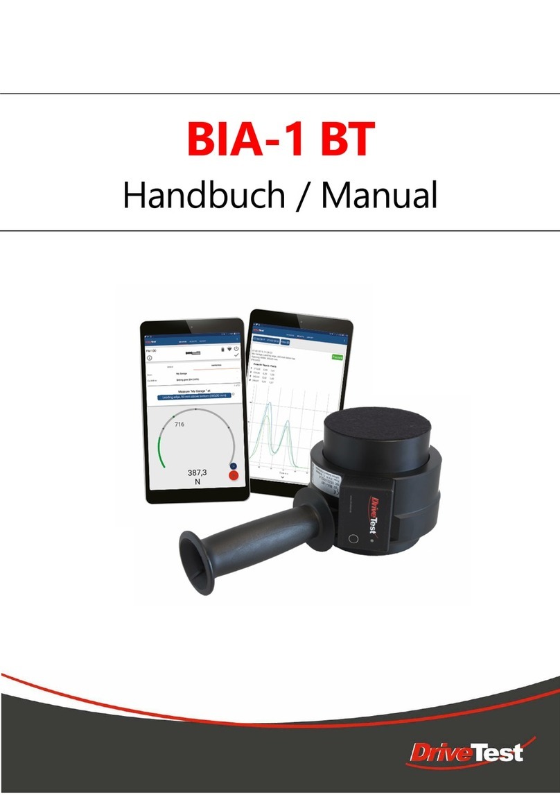
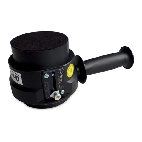
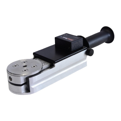
DriveTest FM200 User manual

FM200
System for measuring the closing force
of car windows, sunroofs and doors
Manual

Drive Test GmbH Munich Manual System FM200 Page 2 of 35
Version 5.8 Archive: 0280 Manual V5_8 FM200
CONTENT
1GENERAL DETAILS..................................................................................5
1.1 PURPOSE OF USE....................................................................................5
1.2 STARTING UP ...........................................................................................5
1.2.1 Determining the completeness of the system..............................................5
1.2.2 Installing PC software PinchPilot...............................................................6
1.2.3 Testing / setting sensor interface................................................................6
1.2.4 Testing / setting real time clock of display unit............................................6
1.3 TRANSPORT .............................................................................................6
1.4 PLACING OUT OF OPERATION................................................................6
1.5 STORAGE ENVIRONMENT.......................................................................6
2SHORT OPERATION INSTRUCTIONS .....................................................7
2.1 MEASURING..............................................................................................7
2.2 EVALUATION.............................................................................................7
3PINCH FORCE SENSOR...........................................................................8
3.1 BASIC CONSTRUCTION...........................................................................8
3.2 SENSOR DATA..........................................................................................8
3.3 MAINTENANCE..........................................................................................8
4DISPLAY UNIT SEB2 ................................................................................9
4.1 DISPLAY, OPERATING ELEMENTS..........................................................9
4.2 MEMORY CAPACITY...............................................................................10
4.3 EVALUATION...........................................................................................10
4.4 DATA TRANSFER....................................................................................10
4.5 BASIC SETTINGS....................................................................................11
4.5.1 Erase memory..........................................................................................11
4.5.2 Limit value for peak force..........................................................................11
4.5.3 Mode of measurement (single, dual or triple)............................................11
4.6 BATTERY.................................................................................................12
4.7 ERROR MESSAGES................................................................................12
4.8 MAINTENANCE........................................................................................12
5PC-SOFTWARE PINCHPILOT.................................................................13
5.1 INSTALLATION........................................................................................14
5.1.1 System requirements................................................................................14
5.1.2 Installation ................................................................................................14
5.1.3 Language .................................................................................................14
5.1.4 Software Updates.....................................................................................14

Drive Test GmbH Munich Manual System FM200 Page 3 of 35
Version 5.8 Archive: 0280 Manual V5_8 FM200
5.1.5 Uninstalling...............................................................................................14
5.2 END USER LICENSE AGREEMENT........................................................15
5.3 GENERAL OPERATING STANDARD......................................................16
5.4 MAIN MENUE...........................................................................................16
5.5 MEASURE DATA .....................................................................................17
5.5.1 File name..................................................................................................17
5.5.2 Location of files.........................................................................................17
5.5.3 Properties.................................................................................................17
5.5.4 Details ......................................................................................................18
5.5.5 Data Administration ..................................................................................18
5.5.6 Single/Triple Measurement.......................................................................19
5.5.7 Export.......................................................................................................19
5.5.8 Print..........................................................................................................19
5.6 SETTINGS................................................................................................20
5.6.1 Extra/Options............................................................................................20
5.6.2 Extras/Settings .........................................................................................21
5.6.3 Sensor/Configuration................................................................................21
5.6.4 Operating Bars .........................................................................................22
5.7 MEASURING............................................................................................23
5.7.1 Normal operation......................................................................................23
5.7.2 Controlled by PinchPilot............................................................................23
5.8 SOFTWARE MAINTENANCE...................................................................24
5.9 SOFTWARE PLUG-INS............................................................................24
5.9.1 Q-DAS......................................................................................................24
5.9.2 Label.........................................................................................................24
6MEASURING............................................................................................25
6.1 PREPARATION........................................................................................25
6.2 NOTE MEASUREMENT...........................................................................25
6.3 TURN ON DISPLAY UNIT, SET LIMIT.....................................................25
6.4 PUT SENSOR IN MEASURING POSITION..............................................26
6.5 MEASURING............................................................................................27
7EVALUATION ..........................................................................................27
7.1 LOAD MEASURE DATA FROM DISPLAY UNIT (UPLOAD).....................27
7.2 ENTER MEASUREMENT PROPERTIES.................................................27
7.3 PRINT MEASUREMENT PROTOCOL .....................................................27
8MEASUREMENT SEQUENCE.................................................................28
8.1 TEMPLATES............................................................................................29
8.2 DETAILS TO WORK WITH SEQUENCES................................................29
8.3 OPTIONS .................................................................................................30
8.3.1 Wrong guideline, wrong limit.....................................................................30
8.3.2 Unsaved changes.....................................................................................30

Drive Test GmbH Munich Manual System FM200 Page 4 of 35
Version 5.8 Archive: 0280 Manual V5_8 FM200
9GUIDELINES, STANDARDS....................................................................31
10 TECHNICAL DATA..................................................................................32
11 CALIBRATION.........................................................................................33
12 GUARANTY .............................................................................................33
13 SERVICE ADRESS..................................................................................33
14 DECLARATION OF CE - CONFORMITY.................................................34
15 APPENDIX...............................................................................................35
15.1 ERROR MESSAGES DISPLAY UNIT.......................................................35

Drive Test GmbH Munich Manual System FM200 Page 5 of 35
Version 5.8 Archive: 0280 Manual V5_8 FM200
1 GENERAL DETAILS
1.1 PURPOSE OF USE
The purpose of use of the Force Meter FM200 is to measure the closing force of power
operated closing systems like
- Car windows,
- Car sunroofs,
- Elevator doors,
- machine Protection equipment.
- etc.
The force meter FM 200 evaluates the measured results with respect to the requirements of
applicable standards (refer to chapter “Standards”).
1.2 STARTING UP
1.2.1 Determining the completeness of the system
- 1 Sensor FM200
- 1 Display unit SEB2
- 1 USB-COM Adapter
- 1 Data cable SubD-9-pol.
- 1 Manual with PinchPilot-CD (placed in the cover of the transport case)
- 1 Calibration certificate
- 1 Transport case
Position plan
PC-Data cable
Sensor-
Electronic-Box
Sensor cable
USB-COM
Adapter
Force Sensor
FM200

Drive Test GmbH Munich Manual System FM200 Page 6 of 35
Version 5.8 Archive: 0280 Manual V5_8 FM200
Testing measurement function
- connect sensor with the display unit,
- turn on the display unit (briefly press push button),
- start a measurement (briefly press push button),
- put a load on the sensor and remove it,
- after the measurement duration has expired, the peak force measured is displayed.
1.2.2 Installing PC software PinchPilot
- insert PinchPilot CD,
- start PinchPilot setup application,
- follow the installer instructions,
- Select your language (Extras/Sprache/English).
1.2.3 Testing / setting sensor interface
- if needed install USB driver
- enter sensor interface setting (Extra/options/sensor)
- connect display unit to PC,
- turn display unit on (briefly press push button)
- select upload (tool bar: cube with red arrow)
- Status indication in lower left corner of upload window must be “ready”
1.2.4 Testing / setting real time clock of display unit
- turn on the display unit (briefly press push button),
- start PinchPilot,
- test clock time of display unit (Sensor/Configuration), if necessary, use the button “set
on system time” to set the display unit clock.
1.3 TRANSPORT
For any transport of the instrument the transport case should be used.
1.4 PLACING OUT OF OPERATION
When the instrument will not be used for a longer period of time, please regard these
measures:
- Check if data to be used is still stored in the display unit (if so, upload data),
- Remove battery from display unit.
1.5 STORAGE ENVIRONMENT
The instrument should be stored in a dry environment within the limits of storage temperature
(refer to “Technical Data”).

Drive Test GmbH Munich Manual System FM200 Page 7 of 35
Version 5.8 Archive: 0280 Manual V5_8 FM200
2 SHORT OPERATION INSTRUCTIONS
2.1 MEASURING
0.
Turn off !
press button long (2s).
1.
Turn on !
connect sensor to display unit,
briefly press push button,
set limit if needed,
yellow LED flashes slowly.
2.
Note !
note memory-no. of display unit,
together with point of measurement.
3.
Sensor in Measuring position !
press static sensor side onto
static side of closing system.
4.
Start Measuring !
briefly press push button,
system tares, yellow LED flashes fast.
5.
Initiate closing process !
wait for end of measurement,
green or red LED is on (ok / not ok).
6.
Measurement is valid ?
yes: briefly press push button,
no: press button button long.
2.2 EVALUATION
1.
Connect !
connect display unit to PC,
briefly press push button of display unit,
start PinchPilot.
2.
Upload !
load measurements into the PC:
tool bar: cube with red arrow
3.
Enter properties !
Select measurements, tool bar: arrows
enter properties, tool bar:
paper with red check mark
4.
Print !
start printout, tool bar: printer symbol

Drive Test GmbH Munich Manual System FM200 Page 8 of 35
Version 5.8 Archive: 0280 Manual V5_8 FM200
3 PINCH FORCE SENSOR
3.1 BASIC CONSTRUCTION
The instrument consists of a static and a moveable side. Both sides are linked by a strain
gauge sensor and two leaf springs. The leaf springs has a defined stiffness.
The upper force initiation angle can be moved to perform different gaps.
Side view FM200
3.2 SENSOR DATA
Important sensor specific data is stored in a non-volatile memory (EEPROM), situated in the
sensors connector (9-pol. Sub-D). The sensor data in detail is:
- Force adjustment data,
- Sensor-ID,
- Version,
- Serial-No. ,
- Guidelines category,
- Date of last calibration,
- Number of measurements.
3.3 MAINTENANCE
The instrument has to be protected from moisture. It is designed to withstand normal handling
and transportation, nevertheless excessive shock or load (>500 N) can damage it and should
be avoided. Most of the parts are fabricated from aluminium or stainless steel. To clean the
device, wipe it with a damp cloth.

Drive Test GmbH Munich Manual System FM200 Page 9 of 35
Version 5.8 Archive: 0280 Manual V5_8 FM200
4 DISPLAY UNIT SEB2
The functions of the display unit SEB2 are::
- Controlling measurements,
- Storing measurements,
- Display and evaluation of measured values and evaluation directly after measuring,
- Upload measured data into a PC.
4.1 DISPLAY, OPERATING ELEMENTS
The display elements are three LED`s and a 3 ½ digit LCD-display.
The meaning of the LEDs are:
There is one push button to operate the display unit:
The function of the operating push button is different, according to the state of the display
unit. In the “off” state, the display unit will be turned on. In the “on” state, the display unit can
be turned off by pressing the push button longer than 2 s.
Status-LED
Operating push button
Result-LED: not OK
Result-LED: OK

Drive Test GmbH Munich Manual System FM200 Page 10 of 35
Version 5.8 Archive: 0280 Manual V5_8 FM200
After initialisation, the display unit will enter the ready state. The state LED flashes slowly.
The number of the next free memory location is displayed.
In case of an expired calibration period (> 15 month), the red result LED flashes (refer to
chapter “calibration”).
Display of the next free memory no. :
Single/Triple measurement
Memory No.
Measurement-
No.
Display
Single Measurement
1
1
.01.
Triple Measurement
1
1
.01.1
Triple Measurement
1
2
.01.2
Triple Measurement
1
3
.01.3
4.2 MEMORY CAPACITY
Measurement data is stored in a compressed format. The capacity of the memory is
- 100 single measurements or
- 80 triple measurements.
4.3 EVALUATION
The peak force over the entire measurement period is displayed. This value is compared with
the permissible peak force. Additionally the pulse duration is compared with the actual limit
value. Depending on this comparison, the red or green LED will be lit.
4.4 DATA TRANSFER
The transfer of data is controlled by the software PinchPilot on a personal computer
(PC). The Display unit has to be connected to the appropriate COM- or USB-port
and is turned on by pressing briefly on the push button of the display unit. The data
transfer is controlled by the PC-software PinchPilot.

Drive Test GmbH Munich Manual System FM200 Page 11 of 35
Version 5.8 Archive: 0280 Manual V5_8 FM200
4.5 BASIC SETTINGS
Some basic settings can be modified at the display unit. All of these settings are modified
during the turn on phase of the display unit.
Note: To return to the initial “on” state it might be necessary to turn the display unit off.
Pressing the operating button longer than 2 s does this.
4.5.1 Erase memory
This function erases all stored data in the display unit. Make sure the display unit is turned
off. Press the push button for a time longer than 2 seconds. This will turn the display unit on;
for a shot time three dashes (---) appear, indicating that all data is erased. After this action,
the next available memory no. will be 01.
4.5.2 Limit value for peak force
Certain guidelines have, depending on the nature of the measuring point, different peak force
limits. Up to three different limit values are available. The setting of the peak force limit before
a measurement makes the evaluation easier.
Setting: After turning the display unit on, the actual peak force limit is displayed for a time of 2
seconds. Every short press of the push button during this phase will change the limit to the
next value.
4.5.3 Mode of measurement (single, dual or triple)
Depending on the standard, a single, a dual or a triple measurement is needed. An additional
setting for dual and triple measurement is the option auto sequence. In this case, the second
and if applicable the third measurement is started automatically. The user can fully
concentrate on the closing system to be tested.
Setting: After turning the display unit on, the actual peak force limit is displayed for a time of 2
seconds. When pressing during this period the push button on the display unit for a time
longer than 2 seconds, the mode setting is entered. The actual mode is displayed (refer
table) is displayed for another 2 s. A short press on the push button causes a change to the
next mode.
Alternatively this setting can be done via PC software PinchPilot (refer chapter
“Sensor/Configuration”).
Display
Meaning
1
Single Measurement
3
Triple Measurement
+3
Triple Measurement with Auto Sequence
2
Dual Measurement
+2
Dual Measurement with Auto Sequence

Drive Test GmbH Munich Manual System FM200 Page 12 of 35
Version 5.8 Archive: 0280 Manual V5_8 FM200
4.6 BATTERY
When the message „BAT“ is permanently indicated on the LCD display, it is time to change
the battery. A special capacitor ensures that no measurement data will be lost and the real
time clock does not stop running.
Change the battery by removing the cap on left hand side of the display unit. Pressing the
two locking buttons does this.
Battery change
Caution! Do not tilt one of the caps sideways; this can damage the locking element.
4.7 ERROR MESSAGES
If the display unit detects a malfunction, an error message is displayed (Exx). The meaning of
the two digit error no. is explained in the appendix table “error messages”.
4.8 MAINTENANCE
The display unit does not need any special maintenance. It should not be exposed to direct
sunlight. When dirty, clean it carefully with a soft, damp cloth.

Drive Test GmbH Munich Manual System FM200 Page 13 of 35
Version 5.8 Archive: 0280 Manual V5_8 FM200
5 PC-SOFTWARE PINCHPILOT
Main functions of the PinchPilot Software are:
- Readout of measurement data stored in the display unit,
- Graphic visualisation,
- Calculation of important characteristic values,
- Evaluation of measurements on the base of guidelines,
- Printout of measurement reports and storage of measurement data.

Drive Test GmbH Munich Manual System FM200 Page 14 of 35
Version 5.8 Archive: 0280 Manual V5_8 FM200
5.1 INSTALLATION
5.1.1 System requirements
The PinchPilot software can be installed on any personal computer that meets the following
requirements:
- Operating system Windows 98 SE, NT, 2000, XP, VISTA, W7, W8
- CPU Pentium, 133 MHz
- RAM 32 MB
- Free hard disk memory 50 MB
- CD-drive
- RS232-Interface (COM or alt. USB-Adapter)
For the execution of force measurements, the software is not needed. Therefore, it can be
installed on any work station with access to a printer and an interface channel COM or USB.
For installation, insert the CD and start the setup application and follow the instructions of the
installer.
5.1.2 Installation
Insert CD and start the setup application of PinchPilot using the Windows explorer.
Everything else will run automatically. During the installation process you are asked to enter
the license code. The license code is an 18-digit combination of numbers and letters. It is
situated on a label on the CD-envelope. Upper/lower cases make no difference (not case
sensitive). If the license code is not accepted by the installer, licensing should be repeated
later in the PinchPilot program. We recommend choosing the standard installation option.
For demonstration purposes the PinchPilot software can be started without entering a
license code (enter Ignore).
After successful installation PinchPilot can be started via
“start/programs/PinchPilot/PinchPilot.exe”. Alternatively the user may install a desktop link to
the application.
Activity check: Test if PinchPilot has everything under control:
Mouse click on the PinchPilot symbol on the screen and it will give you a subtle hint !
5.1.3 Language
Available languages are German, English, French, Italian and Spanish. The setting is found
under: “Extra/Language” (“Extras/Sprache”).
5.1.4 Software Updates
The update installation procedure is the same as the original installation. It is not necessary
to uninstall the former version of PinchPilot. Again, the license code is situated on the CD
envelope. In order to prevent a mix up of CD envelopes, the license code label also contains
the software version number. The version number is also found on the CD-Label.
5.1.5 Uninstalling
To uninstall PinchPilot, you select in Windows:
„Settings/Control Panel/Add,Remove Programs/PinchPilot”
“Add/Remove”
All PinchPilot components are removed from the PC.

Drive Test GmbH Munich Manual System FM200 Page 15 of 35
Version 5.8 Archive: 0280 Manual V5_8 FM200
5.2 END USER LICENSE AGREEMENT
By installing the software on his PC the end user accepts the conditions of this agreement:
The end user has the right to install the software on one Computer at a time. There is no time
limit for using the software. The user can copy the software for backup purposes.
The software is licensed and not sold. The holder of all rights is Drive Test GmbH.
Drive Test GmbH warrants that the software is substantially free from defects for a period of
one year.
Drive Test GmbH doesn’t take any liability for resulting damages resulting from the usage of
the software as far as it can be legally excluded.
Drive Test GmbH doesn’t warrant that the software will run on every PC-system.

Drive Test GmbH Munich Manual System FM200 Page 16 of 35
Version 5.8 Archive: 0280 Manual V5_8 FM200
5.3 GENERAL OPERATING STANDARD
The operation of the software is based on the Windows standard and should be known to
most of the users. The easiest way to operate the software is a mouse-based operation;
nevertheless, a keyboard-based operation is also possible. In the following description only
specific functions are explained; general functions like “save” etc. are considered as known to
the user. The access description below is based on the menu bar (frequently used functions
may also be activated directly via tool bar).
5.4 MAIN MENUE
After starting PinchPilot by double clicking the PinchPilot-Icon the main menu is displayed.
Four diagrams:
In the middle of the screen there are four diagrams. They represent three single
measurements and additionally a fourth diagram displaying all three measurements. Each of
the four diagrams can be displayed in a single diagram view.
Menu Bar:
At the upper screen margin there is the menu bar. This bar offers access to all PinchPilot
functions.
Tool bar:
The tool bar is below the menu bar. This bar offers a fast mouse access to often used
functions. All functions can also be activated in several steps via menu bar.
Results:
The result values are displayed in a table in the lower screen area. Result values are discrete
values needed for evaluation purposes based on the active guideline, such as the peak force
of a measurement. Each of these values is evaluated on the basis of the active guideline and
indicated to be ok or not ok. Besides the values of single measurements, the average values
of the three measurements are also evaluated. The total evaluation result is displayed in a
separate result field with a significant ok / not ok display.

Drive Test GmbH Munich Manual System FM200 Page 17 of 35
Version 5.8 Archive: 0280 Manual V5_8 FM200
5.5 MEASURE DATA
Measurement data is found in measurement data files. Within the PinchPilot-program the
expression “file” is equivalent with measurement data file.
5.5.1 File name
The name of measurement data files is composed of several components:
aaaa bbb cc.ppd
aaaa ..Serial No. of the sensor; this part of the name can be activated or deactivated. It is set
under „Extras/Options/Sensor/Serial No. in file name“.
The serial no. as part of the name is especially important when more than one sensor
is in use. When only one sensor is used, this feature should be deactivated.
bbb ... Continuous block no. This number is incremented at every upload session (transfer of
measurement data from display unit to the PC). The block no. can be set under
„Extras/Options/Sensor/Bloc No.“.
cc ... No. of the measurement (00-99)
ppd ... Type specific file extension: PinchPilot Data.
5.5.2 Location of files
Before uploading data, a destination directory can be selected („Sensor/Load Measure
Data/Find“). At the next upload the former directory will be offered.
When loading measure data files stored in the PC, the location can be selected freely. At the
next loading the last entered directory will be offered.
5.5.3 Properties
Properties of measurement data are important attributes like name of the customer, point of
measurement etc. . All properties appear on the printed report. Without properties
measurement data can be easily mixed up and have little information value.
Properties are set under „File/Properties“. Changes are valid for the currently loaded
measurement. Default setups are also valid for future uploads.

Drive Test GmbH Munich Manual System FM200 Page 18 of 35
Version 5.8 Archive: 0280 Manual V5_8 FM200
The properties of a measurement data file are entered under “File/Properties”:
Name
Meaning
Example
Guideline
Name of the applicable standard
EN12445/EN12453
Tester
Name or code of testing person
Charles Clamp
Customer
Name or code of customer/ Dep. etc.
Bentley Motor Cars
Item
Identification of the item
Door 1
System
Identification of the system
Automatic
Limit
Applicable limit value
1400 N
Measure Point
Identification of the measuring point
Lower edge
Remark
Special details, etc.
New drive system
Depending on the guideline, the names may vary.
In the field “Remarks” additional measurement information can be entered.
In the field “Measure Points” a number of frequently used names of measurement points can
be defined. These names will be selectable in “Measure/Measure Point”.
All inputs are valid for the currently loaded measurement. In addition, a set of properties can
be defined as a default setting. Default settings are inserted automatically when
measurements are uploaded.
Default settings are guideline specific, i.e. only available in the corresponding guideline.
For measurements that have to be executed periodically and include several measurement
points, usage of the database option is recommended. All properties of all measurement
points can be defined within the database and transferred into a selected number of
measurements with one mouse click. Refer to chapter “database”.
5.5.4 Details
In addition to the course of the force and the result values displayed in the main menu, there
are a number of information details linked to the measurement.
These details can be displayed under „View/Details“. In case of malfunction, this information
can be useful.
5.5.5 Data Administration
The administration of measurement data files has to be organised externally via the Windows
Explorer. By this means, files can be deleted, moved or saved.
We recommend creating an adequate folder structure for clearly arranging data.

Drive Test GmbH Munich Manual System FM200 Page 19 of 35
Version 5.8 Archive: 0280 Manual V5_8 FM200
5.5.6 Single/Triple Measurement
Depending on the setting „Sensor/Configuration/Mode“ a measurement data file can consist
of one or three measurements.
5.5.7 Export
Depending on the intended purpose, measure data can be exported in different formats. The
following options are offered under „File/Export“:
Text Format:
Unformatted text, which can be imported by programs like MS EXCEL. The number of
exported measure values can be set under „Extras/Options/Measuring/Time Distance“.
Measurement Report:
A measurement report is the printable result of a measurement. The data format is EMF
(Enhanced Meta Format). MS WORD can import it.
PDF:
The measurement protocol is saved in a PDF formatted file. Advantages of this format are:
- can be sent via email,
- cannot be changed,
- is readable with Acrobat Reader without any other software needed.
Diagram:
A diagram is a single diagram. The active diagram is indicated by a blue coloured title. This
diagram will be exported when the export is initiated. The data format is EMF (Enhanced
Meta Format). MS WORD can import it
Q-DAS:
See Software Plug-Ins
5.5.8 Print
The printing features can be accessed under „File/Print“:
- Selection and setting of a printer,
- Preview before printing,
- Starting the print.

Drive Test GmbH Munich Manual System FM200 Page 20 of 35
Version 5.8 Archive: 0280 Manual V5_8 FM200
5.6 SETTINGS
PinchPilot offers versatile settings. The default software installation settings ensure
reasonable values so that the user has to adapt very few values.
5.6.1 Extra/Options
Submenu
Value
Meaning
Sensor
Port (PC interface)
depending on the connection either
Com1,2,3,4. (for changes to become
effective, a restart of PinchPilot is
required)
Sensor
Serial No. part of the
file name
select this feature when several
sensors are in use, otherwise do not
Sensor
Delete after upload
delete measurement data in the
display unit after uploading this data
into the PC. Should be set
Sensor
Change Guideline
redefines guideline when uploading
measure data
Sensor
Open last Upload
load and display the last
measurement after an upload session
Sensor
Bloc No.
the bloc no. defines the upload
session. Adapt when needed
Sensor
Compression
Compressed data transfer for shorter
transfer duration, set active
Tester Properties
Logo
corporate logo, if available and
desired
Tester Properties
Properties appear in
report
Text appears in the right, upper field
of the report; e.g., postal address etc.
Print
Logo Margins
sets the logo position for printed
report
Print
Diagram
1 or all diagrams printed
set all
Print
Punch marks
set active
Display
Average
Time for averaging of force values
when using PC controlled measuring
Refer to chapter Measuring controlled
by PinchPilot
Plug-Ins
Export Q-DAS Files
(Option)
Activation/Deactivation
Refer to chapter Plug ins
Plug-Ins
Import Label Data
(Option)
Activation/Deactivation
Refer to chapter Plug ins
This manual suits for next models
1
Table of contents
Other DriveTest Measuring Instrument manuals
Popular Measuring Instrument manuals by other brands

Milwaukee
Milwaukee Mi 190 manual

Endress+Hauser
Endress+Hauser Proline t-mass 65 operating instructions

ElektroPhysik
ElektroPhysik QuintSonic 7 Technical manual and operating instructions

Chauvin Arnoux
Chauvin Arnoux C.A 6240 operating manual

HACH LANGE
HACH LANGE LINK2SC user manual

ABB
ABB RGM40 meter quick start guide