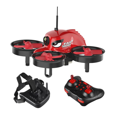
DRONE ART Xtreme V2 User manual

Xtreme V2
88025RC (RtF)
Operating instructions

2

3
1. Introduction ..................................................................................................4
2. Latest operating instructions ........................................................................4
3. Symbols .......................................................................................................4
4. Intended use ...............................................................................................4
5. Safety instructions........................................................................................5
5.1 Persons/Product ................................................................................5
5.2 Before commissioning .......................................................................5
5.3 During operation ................................................................................5
5.4 Outdooryinglocations .....................................................................6
5.5 Batteries.............................................................................................6
5.5.1 General information ..........................................................6
5.5.2 LiPo batteries....................................................................6
5.6 Miscellaneous....................................................................................8
6. Accident prevention......................................................................................8
7. Emergency stop ...........................................................................................8
8. Charging and installing battery.....................................................................9
8.1 Charging ............................................................................................9
8.2 Installing the battery.........................................................................10
9. Installing propellers and guards .................................................................11
9.1 Installing...........................................................................................11
9.2 Removing.........................................................................................11
10. FPV Camera and antenna .........................................................................12
11. Video TX.....................................................................................................12
12. Propeller Block Auto Stop ..........................................................................12
13. Basic control ...........................................................................................13
14. Mode 2 Control...........................................................................................15
15. Auto-ip......................................................................................................16
16. Altitude hold ...............................................................................................17
17. Binding the transmitter ...............................................................................17
18. Emergency auto level.................................................................................17
19. Remote OSD Menu....................................................................................18
20. Photo and Video modes.............................................................................18
20.1 Photo taking.....................................................................................18
20.2 Video recording................................................................................18
20.2.1 Start ................................................................................18
20.2.2 Stop ................................................................................18
21. Video channel selection - Automatic ..........................................................19
22. Video channel selection - Manual ..............................................................19
22.1 Xtreme V2 ......................................................................................19
22.2 Transmitter.......................................................................................19
23. Preightchecklist .......................................................................................19
24. Status Indications.......................................................................................20
25. Technical data ............................................................................................22
26. Disposal .....................................................................................................23
26.1 General............................................................................................23
26.2 (Rechargeable) batteries .................................................................23
27. Declaration of Conformity...........................................................................23
28. FCC Note ...................................................................................................24
29. Product support..........................................................................................24
30. Legal notes.................................................................................................24
Table of contents

4| Introduction
1. Introduction
Dear customer,
Thank you for purchasing the RC EYE Xtreme V2! We hope you will enjoy your FPV
experienceandthattheV2willbecomeafavoriteyerwhetherit’syourrstdroneorjust
a new drone you are adding to the collection. For the best experience please read and
familiarize yourself with the V2 by reading through this document. It will help you have
afullunderstandingofpreparingforyourrstightandalsoansweranyquestionsyou
might have.
This product complies with the applicable National and European standards and
regulations.Wekindlyrequesttheusertofollowtheoperatinginstructions,topreserve
this condition and to ensure safe operation! These operating instructions relate to this
product. They contain important notices on commissioning and handling. Please take this
into consideration when you pass the product on to third parties.
Please keep these instructions for future reference!
All company names and product designations contained herein are trademarks of the
respective owners. All rights reserved.
We wish you a great deal of enjoyment with your new DroneArt product!
2. Latest operating instructions
Please download the latest version of the operating instructions from our website at
www.droneart.com.Navigatetotheproductpageandopenthe‘Downloads’tab.Clickon
”Operating instructions” to start the download.
3. Symbols
BLUE provides you with additional useful information, and highlights
important facts.
RED stands for danger and alert. Read these sections always to avoid
accidents and product damage.
GREEN stands for good practice, protecting your product from damage.
4. Intended use
TheXtremeV2isamodelquadcoptersolelydesignedforprivateuseinthemodelmaking
area and the operating times associated with this. The Xtreme V2 is not suitable for other
types of use, including commercial applications.
Any use other than the one described can damage the device. Moreover, this involves
dangerssuchasshortcircuit,reandelectricshock,etc.Observethesafetyinformation
under all circumstances! The product must not become damp or wet.
This product is not a toy and not suitable for children under the age of 14.
For safety and approval purposes, you must not rebuild and/or modify this
product. If you use the product for purposes other than those described
above, the product may be damaged. In addition, improper use can
causehazardssuchasshortcircuiting,re,electricshocketc.Readthe
instructions carefully and keep them.
Make this product available to third parties only together with its
operating instructions.

Safety Instructions | 5
5. Safety instructions
Read the operating instructions carefully and especially observe the
safety instructions. If you do not follow the safety instructions and
information on proper handling in this manual, we assume no liability
for any resulting personal injury or damage to property. Such cases will
invalidate the warranty/guarantee.
5.1 Persons/Product
■The device is not a toy. Keep it out of the reach of children and pets.
■Do not leave packaging material lying around carelessly. These may become
dangerous playing material for children.
■If it is no longer possible to operate the product safely, take it out of operation and
protect it from any accidental use. Safe operation can no longer be guaranteed if the
product:
▬is visibly damaged,
▬is no longer working properly,
▬has been stored for extended periods in poor ambient conditions, or
▬has been subjected to any serious transport-related stresses. The product must
not become damp or wet. The Xtreme V2 uses delicate electronic components
whicharesensitivetotemperatureuctuationsandareoptimisedforaparticular
temperature range. Observe the operating temperature range given in the
technical data.
■Do not place the product under any mechanical stress.
■Handle the product carefully. Jolts, impacts or a fall even from a low height can damage
the product.
■
Important note!
Operating the model may cause damage to property and/or individuals.
Therefore,makesurethatyouaresufcientlyinsuredwhenusingthemodel,e.g.by
taking out private liability insurance. If you already have private liability insurance,
verify whether or not operation of the model is covered by your insurance before
commissioningyour model.Note:SomeEUcountriesrequireinsurance forallight
models!
■Observe the laws concerning the use of cameras for surveillance purposes. Observe
theprivacyofothersatightrecordings.Donotlmpeoplewithouttheirpriorconsent.
Always comply with the respective applicable laws and provisions.
5.2 Before commissioning
■Beforeeveryight,checkthefunctionalreliabilityofyourmodelandthetransmitter.
Watch out for any visible damage such as defective plug connections or damaged
cables and wires.
■All moving parts of the model must run smoothly but should not have any play in their
bearings.
■Before each operation check the correct and secure position of the propellers.
■Chargetheightbattery.
■AlwaysswitchonthetransmitterrstbeforepoweringontheXtremeV2.
■Set the throttle to zero before powering on the Xtreme V2. The motors might run
unintentionally!
5.3 During operation
■When the motors are running, make sure that neither objects nor body parts are in the
rotating and suction area of the propellers.
■Do not take any risks when operating the model! Your own safety and that of your
environment is solely down to you being responsible when dealing with the model.
■Improper operation may cause serious injury and property damage! Therefore make
suretokeepasufcientlysafedistancetopersons,animalsorobjectsduringoperation.
■Select an appropriate location for the operation of the Xtreme V2.
■Fly the Xtreme V2 only if your ability to respond is unrestricted. The inuence of
tiredness, alcohol or medication can cause incorrect responses.

6| Safety Instructions
■Do not direct your model towards spectators or yourself.
■Motor,electronicsandightbatterymayheatupduringoperation.Wait5to10minutes
beforerechargingorreplacingtheightbattery.
■
Never switch off the transmitter while the
Xtreme V2
is in use. After landing, always
disconnecttheightbatteryrst.Onlythenmaythetransmitterbeswitchedoff.
■In case of a defect or a malfunction, remove the problem before using the Xtreme V2
again.
■Never expose the Xtreme V2 or the transmitter to direct sunlight or excessive heat for
an extended period of time.
■In the case of a severe crash (e.g. from a high altitude) the electric gyro sensors can be
damagedand/ormisadjusted.Therefore,fullfunctionalitymustbetestedbeforeying
again without fail!
■In the event of a crash, the throttle should be immediately set to zero. Rotating
propellers may be damaged if they come into contact with obstacles. Before ying
again, these should be checked for possible tears or breakages!
■Observe the warn/safety signals emitted by the Xtreme V2 at all times to avoid damage.
5.4 Outdoor flying locations
■AlwaysandonlyoperatetheXtremeV2inadesignatedRCyingarea.
■Stay away from power lines, cellphone towers and other sources of potential
interference, and restricted areas.
■NeverytheXtremeV2aboveornearpeople.
■ContactalocalRCclubnearbytondoutmoreaboutdesignatedandapprovedying
areas.
5.5 Batteries
5.5.1 General information
■Correct polarity must be observed while inserting/connecting batteries.
■
RemovetheightbatteryfromtheXtremeV2aftereveryight.
■
Remove the battery from the transmitter if you do not use it for a longer period of time.
■Batteries must be kept out of the reach of children. Do not leave the batteries lying
around.
■Batteriesmustnotbedismantled,short-circuitedorexposedtore.
5.5.2 LiPo batteries
Aftertheight,theLiPoightbatterymust bedis-connected fromthe
Xtreme V2.
Lithium is a highly reactive chemical element with a high energy density.
In the case of overcharging, the LiPo rechargeable battery packs might
catchreorevenexplode.Therefore,LiPorechargeablebatterypacks
mustalwaysbeputonare-proofsurfaceforchargingandthecharging
process must be supervised.
In no case must the maximum permissible battery pack temperature of
+60°C be exceeded. Otherwise the rechargeable battery may explode!
Caution: Risk of explosion if battery is replaced by an incorrect type.
Dispose of used batteries according to the instructions.
Hazards of LiPo ight batteries
■Do not leave the LiPo ight battery connected when you do not use it (e.g. during
transportorstorage).Otherwise,theLiPoightbatterymaybefullydischarged.This
would destroy it and render it unusable! There is also a danger of malfunction due to

Safety Instructions | 7
interference. The rotors could start up inadvertently and cause damage or injury.
■Rechargeable LiPo batteries are very susceptible to moisture due to the chemicals they
contain!Donotexposethemtomoistureorliquids.Riskofexplosion!
■DonotexposethechargerorLiPoightbatterytohigh/lowtemperaturesortodirect
solar radiation. When handling LiPo batteries, observe the special safety information
of the battery manufacturer!
■NeverchargetheLiPoightbatteryimmediatelyafteruse.AlwaysleavetheLiPoight
batterytocooloffrst(atleast5-10minutes).
■Only charge intact and undamaged batteries. If the external insulation of the
rechargeable battery is damaged or if the rechargeable battery is deformed or bloated,
itmustnotbecharged.Inthiscase,thereisimmediatedangerofreandexplosion!
■NeverdamagetheexteriorofaLiPoightbattery.Nevercutthecoveringfoil.Never
stabanyLiPoightbatterieswithpointedobjects.
■As the charger and the rechargeable LiPo ight battery both heat up during the
chargingprocedure,itisnecessarytoensuresufcient ventilation. Never cover the
chargerortheLiPoightbattery!Ofcourse,thisalsoappliesforallotherchargersand
rechargeable batteries.
■RemovetheLiPoightbatterythatistobechargedfromthemodelandplaceitona
re-proofsupport(e.g.aplate).Keepadistancetoammableobjects.
■DisconnecttheLiPoightbatteryfromthechargerwhenitisfullycharged.
■Chargersmayonlybeoperatedindryrooms.ThechargerandtheLiPoightbattery
must not become damp or wet.
■Never take the rechargeable battery apart! The rechargeable battery may not be
subjected to any mechanical strain!
■Thecontactsmaynotbeshort-circuited,asthereisdangerofreandexplosion!
■Donotexposerechargeablebatteriestore,asthereisariskofexplosion!
■Keep rechargeable LiPo batteries away from children. Store rechargeable batteries in
a dry, cool place.
■If a rechargeable battery is deformed or damaged during a crash, it must no longer be
used. The same applies for “swollen” rechargeable batteries, or rechargeable batteries
with other visible deformation or leaks. Do not attempt to charge such rechargeable
batteries!Dangerofreandexplosion!Disposeofsuchrechargeablebatteriesinan
ecologically sound fashion.
■The general hazard notices for handling batteries and rechargeable batteries also
apply to rechargeable LiPo batteries.
Total discharge
■Since discharging below 3.0 V per cell would lead to permanent damage of the
rechargeable battery pack, this total discharging is to be prevented as far as possible.
■Forsafetyreasons,programmablecruisecontrols/ightcontrolsystemsshouldbeset
in such a way that the undervoltage detection has already responded before a voltage
of 3.0 V per cell is reached (e.g. 3.2 V). Alternatively, optical undervoltage displays are
also recommended.
Correct dimensioning
■As the current drawn rises, the battery pack warms and the usable capacity is lowered.
The ideal operating temperature during discharge is between
+20
and
+40 °C
and must
not exceed
+60 °C
even under extreme load.
■The maximum short-time discharge current is stated in the technical data sheets or can
be read directly from the battery pack. The value “C” always refers to the capacity value
of the respective battery pack.
Example:
A battery pack with a capacity of 2100 mAh and ”20 C” can be dis-charged with 2100
mA x 20 = 42 A maximum.
■However, the maximum permissible continuous current is clearly lower. If there are no
precisemanufacturer’sspecications,thebatterypackshouldnotbedischargedwith
more than approx. 50 % of the maximum permissible surge current over a long term.

8| Accident Prevention
5.6 Miscellaneous
■Consult an expert when in doubt about operation, safety or connection of the device.
■Maintenance,modicationsandrepairsaretobeperformedexclusivelybyanexpert
orataqualiedshop.
■If you have questions which remain unanswered by these operating instructions,
contact our technical support service or other technical personnel. See ‘29. Product
support’onpage24.
6. Accident prevention
We strongly advise you to refrain from stunts until you master the Xtreme
V2innormalyingconditions.
The best learning experience is provided by pilots who have experience
inyingthistypeofaircraft.
Careless operation can cause serious damage and injury. Observe the following:
■OnlyytheXtremeV2outdoorsduringgoodweatherconditions.DonotytheXtreme
V2 during adverse weather (rain, snow, strong winds, etc.).
■Donotywithouthavingcoveredtheelectronics(canopy).Ensurenomoistureenters
the body.
■Keepasufcientclearanceareaduringight.
■DonotytheXtremeV2inthevicinityofpeopleandanimals.
7. Emergency stop
WhentheXtremeV2entersanemergencysituation,aredLEDontheightcontrollerwill
ashwithasolidlitorangeLEDnexttoit(seeillustrationbelow).
In case of an emergency, press the Power / Emergency button (gray colored button) on top
of the Xtreme V2, or the ARM / Emergency button (red colored button) on the transmitter.
Warning!YoucanonlydisarmtheXtremeV2whennotying.

Charging And Installing Battery | 9
8. Charging and installing battery
Warning!Foryourownsafety,removetheightbatterywheneveryou
are asked to do so.
The charger only allows charging 1 battery at one time.
8.1 Charging
■Use the supplied Xtreme V2 battery charger (89155RC) to charge the batteries. Read
thecharger’soperatinginstructionsbeforeusingit.
LED indicator
Charging port for
Flight battery
(with push cover)
Charging port for
Transmitter
battery
2S / 3S
selection
■Flight and transmitter batteries are provided.
Battery for Xtreme V2
(Flight battery)
Battery for transmitter
■Fullychargetheightbatterybeforeyouyandthetransmitterbatterywhennecessary.
1. Connectthecharger’sUSBwiretoasuitablepowersource(inputcurrentmin.4.5A).
Two LED indicators on the charger light up (2 LEDs means 2S).
2. Thedefaultchargingmodeissetfor2Sbatteries.Ifyouwishtochargea3Sight
battery (sold separately), press the 2S/3S button on the charger to toggle between
2S/3S charging modes.
3. Charge the batteries as illustrated below:
Flight battery Transmitter battery
4. Observe the indicator lights on the charger while charging:
2S mode (default) 3S mode
Charging
Solid red Solid red
Fully Charged /
without battery
Solid blue Solid blue

10 | Charging And Installing Battery
8.2 Installing the battery
Installtheightbatteryasillustratedinthefollowingsequenceofdiagrams.
Push the battery all the way in
Fasten velcro strap
Close canopy, and make
sure it is tightly locked in place
ALT-hold
VIDEO
F-mode
FLIP
Connect the transmitter battery and
place it into the battery compartment, then
replace the battery compartment cover.Open the battery compartment as shown.

Installing Propellers And Guards | 11
9. Installing propellers and guards
Warning! Remove the ight battery before you install propellers and
guards!
Overtightening will irreversibly damage the thread in the propeller hub.
In this case you must immediately replace the propeller! Both threads
and bolts of each propeller mount / propeller must be in perfect condition
9.1 Installing
■Only tighten the propellers by hand and little force to avoid damage.
■The motors are reverse threaded. Propellers are tightened by turning them in the
reverse direction of the arrow mark on propeller (indicator of spinning direction of
motor).
1. Install a propeller on each motor by following the propeller diagram to the right .
▬There is a spinning direction marking on each propeller. If propellers are installed
incorrectly,theXtremeV2willnotyandmaybehaveerratically.
2. Install a propeller guard on each side as shown on the bottom right .
9.2 Removing
■Loosen the propeller by hand and pull it off the shaft.
■If the propeller sits too tight, slide the supplied hex tool onto the hex portion of the
motor, then loosen the propeller while countering with the hex tool.
Propeller installation
White color
propeller
Black color
propeller
Spinning mark on
Black color
propeller
Spinning mark on
Spinning mark on
White color
propeller
Spinning mark on
Tightening
direction
Tightening
direction
Tightening
direction
Tightening
direction
Propeller guard installation

12 | Fpv Camera And Antenna
10. FPV Camera and antenna
■Removethecamera’sprotectivecoverbeforeuse.
■The FPV antenna is pre-installed (see below illustration).
MicroSD
card slot
VTx antenna
■TheFPVcamera’stiltanglecanbeadjustedmanually.Youcanrotateupwardsby35
degrees, and downwards by 60 degrees.
11. Video TX
■Real time video transmission is possible via compatible FPV goggles or FPV receivers.
■Read the instructions supplied with the goggles or FPV receivers before you use them.
12. Propeller Block Auto Stop
Ifpropellershitanobjectortheightcontrollerregistersincreasedresistance,themotors
will automatically be shut off. This ensures safety and keeps damage to a minimum should
the Xtreme V2 hit an object.
To re-engage the motors proceed as follows:
1. Disarm the Xtreme V2 by pressing the ARM button on remote control.
2. Turn off the Xtreme V2 by pressing the Power button on top of the Xtreme V2.
3. With the Xtreme V2 turned off, you can safely inspect it for damage.
4. If no damage was caused, turn it back on by pressing the Power button on top of the
Xtreme V2.
5. Arm the Xtreme V2 by pressing the ARM button on the transmitter.

Basic Control | 13
13. Basic control
Study below diagrams before operating the Xtreme V2.
Manual
channel
button
Manual channel button
(beneath the hatch)
Power button /
emergency button
Canopy
TOP BOTTOM
LEDs inside
LEDs inside
FPV camera with
adjustable angle
FRONT
MicroSD
card slot Video TX antenna
BACK
Micro USB port
SIDE

14 | Basic Control
ToavoidanymisbehavioroftheXtremeV2,andasacommonsafetypractice,alwaysfollowthesequence:
Powering ON:
First power ON the transmitter, then power ON the Xtreme V2.
Powering OFF:
First power OFF the Xtreme V2, then power OFF the transmitter.
ALT-hold
VIDEO
F-mode
FLIP
TFT monitor
Power on
indicator
On / Off Elevator trim
Aileron trim
Arm/Disarm button /
emergency button
Rudder trim
Strap mount
Scan
(Auto video channel
scan)
Menu
+
(manual band selection)
Flight mode
1. Beginner
2. Sport
3. Sport acro
4. Expert
Flip
Video
Video out
Aileron / Elevator
Throttle / Rudder
–
(manual channel selection)
Altitude hold/
Bind

Mode 2 Control | 15
14. Mode 2 Control
Arm/Disarm button /
emergency button

16 | Auto-flip
15. Auto-flip
Only available for Beginner, Sport and Sport Acro modes
Onlyperformipsoutdoorsinanopenspaceenvironment.Performing
ipsinasmallareacancausedamageand/oraccidents.
VIDEO
FLIP
When flip is activated front LEDs are lit solid light blue.
1. PresstheFlipbuttononthetransmitteroncetoenteripmode.Ashortdoublebeep
is emitted and all LEDs on the transmitter will give a short blink; the front LED on the
Xtreme V2 is lit solid light blue.
2. Givestickinputforipdirection.Seeillustrationstotheright
3. TheXtremeV2ips.
Note:
TheXtremeV2ipmodehasasafetytimeoutfeature.IfafteryoupressedtheFlip
button you do not move the Aileron / Elevator stick within 2 seconds, the Xtreme V2 will exit
ipmodeandreturntothepreviousyingmode.

Altitude Hold | 17
16. Altitude hold
Only available for Beginner and Sport modes
■Pressing the ALT-Hold button toggles the altitude hold function on/off.
ALT-hold
F-mode
■If Alt-Hold is activated, the colour of the LEDs on the front arms alternatingly change
betweenorangeandtheightmodecoloreverysecond.
Above illustrated example:
Green front LEDs designates beginner mode. When Alt-hold is activated, the front LEDs
change every second as follows:
Orange > Green > Orange > Green
17. Binding the transmitter
Transmitter and receiver are bound during production. In case it becomes necessary to
rebind transmitter and receiver follow the following steps:
1. Remove the propellers for safety reasons.
2. Power on the Xtreme V2, leave the transmitter turned off.
3. Wait approx. 10 seconds and on the side of your Xtreme V2 you will see a little orange
LEDlightashingononeofthesideholes.ThismeanstheXtremeV2isinbindmode.
4. Hold down the ALT-Hold button on the transmitter while turning on the transmitter by
pressing the power button on the radio.
5. Release the ALT-Hold button once powered on. Wait a few moments.
6. TheorangeLEDontheXtremeV2shouldmakeafewashesandgosolid.
7. Binding is complete.
8. Install the propellers again.
18. Emergency auto level
In expert mode (auto level disengaged) you have an emegergency auto levelling feature
available.
If at any time during practicing in this mode you lose orientation or control over your Xtreme
V2 you can engage the auto level feature to assist you in regaining control.
Toengagetheautolevelfeatureinightinexpertmode,holddowntheightmodebutton
F-mode
on the transmitter for more than 0.5 s. Auto level remains enganged as long as you
holddowntheightmodebutton.Releasetheightmodebuttontodisengageautolevel.

18 | Remote Osd Menu
19. Remote OSD Menu
Transmitter
battery level
Video signal
strength
Receiver channel Frequency
channel
Recording
duration
20. Photo and Video modes
20.1 Photo taking
■Totakeaphoto,pressthevideobuttononcequickly.
■Eachtakenphotoisconrmedbyadoublebeep.
20.2 Video recording
20.2.1 Start
■To start video recording, long press the video button.
■Startofrecordingisconrmedbyasinglebeep.
■Therecordingnoticationtimeronthe4.3”monitorfadesin.
20.2.2 Stop
■To stop video recording, long press the video button.
■Stopofrecordingisconrmedbyasinglebeep.
■Therecordingnoticationtimeronthe4.3”monitorfadesout.

Video Channel Selection - Automatic | 19
21. Video channel selection - Automatic
Your Xtreme V2 comes out of the box already bound to the transmitter. Once transmitter
and Xtreme V2 are powered on and you do not see the live feed image on the transmitter
screen after a few seconds start the auto channel scan.
Hold down the
SCAN
button on the transmitter for a short moment then release it. The
videoreceiversystemwillautomaticallyscanandndthecurrentbandandchannelthat
your Xtreme V2 is on and bind.
Important note: sometimes Auto channel scan will connect to a
neighboring band/channel. This can limit video range and reception.
If you experience either of these limitations please refer to chapter ‘22.
Videochannelselection-Manual’onpage19.
22. Video channel selection - Manual
To manually change the channel/band proceed as described in the following chapters.
22.1 Xtreme V2
1. Turn Xtreme V2 and transmitter off.
2. Remove the video transmitter hatch to get access to the manual channel button. Also
refer to chapter ‘13.Basiccontrol’onpage13.
3. Turn Xtreme V2 and transmitter on.
4. Quickly press the button. The current band and channel will be displayed in the top
right corner of the transmitter screen.
5. Holddownthebuttonforabout1.5secondsuntilthechannelashesonthescreen.
6. Repeatedly press the button to cycle through the available channels/bands until the
frequencyyouwishtouseisdisplayed.Thechannel/bandisautomaticallysavedwhen
you stop cycling. Allow a short amount of time for the saving procedure to complete.
22.2 Transmitter
1. Press the scan button
SCAN
to display the current channel/band.
2. Press the
+
buttononthetransmittertochangethefrequencyband.Pressthe
–
button
tochangethevideochannel.Cycleuntilyoundthefrequencyyouwishtouse.
3. The channel/band is automatically saved when you stop cycling. Allow a short amount
of time for the saving procedure to complete.
23. Preflight checklist
Before turning on the transmitter and Xtreme V2, please run through below checklist:
■Are the propellers installed in correct orientation?
■Are the propellers secured and undamaged?
■Are the batteries in good condition and fully charged?
■Istheightbatteryproperlysecured?
■Is the battery door properly closed?
■Is a microSD card installed (in case of using on board recording)?

20 | Status Indications
24. Status Indications
The following reference charts are your quick guide to functions, LED and beeping
indications.
Main Functions
F-mode
Beginner Sport Sport acro
Expert
Autoip Yes Yes Yes No
Auto level Yes Yes Yes No
Alt. hold Yes Yes No No
Description Auto level with 11
degree limit
Auto level with 18
degree limit
No angle limit.
Manualipsand
rolls are allowed.
No angle limit. Alt.
hold not available.
Rates are high.
LED
indication
Drone
Front: Green
Rear: Red
Front: Blue
Rear: Red
Front: Magenta
Rear: Red
Front: Yellow
Rear: Red
Remote
LED 2 solid LED 3 solid LED 3 blinks LED 4 solid
Alarm Functions
Alarms Description Indication
Xtreme V2 Transmitter
Alarm/Error
Any abnormal
situation about
Xtreme V2
Front and rear LEDs blinking white and
swappingwithcurrentightmode’sLED
color.
Example: Beginner mode
--
Battery low
•
Low:
Need to
proceed landing
•
Extremely
low:
Must land
immediatelty
Front and rear LEDs blinking red and
swappingwithcurrentightmode’sLED
color.
Example: Beginner mode
All LEDs blinking
and buzzer beeping
Signal loss
-- • All LEDs blink fast: Yellow-Blue-Yellow-
Blueandswappingwithcurrentight
mode’sLEDcolor.
• Buzzer beeps: 0.5s ON – 0.5s OFF
Example: Beginner mode
--
This manual suits for next models
1
Table of contents
Other DRONE ART Drone manuals
