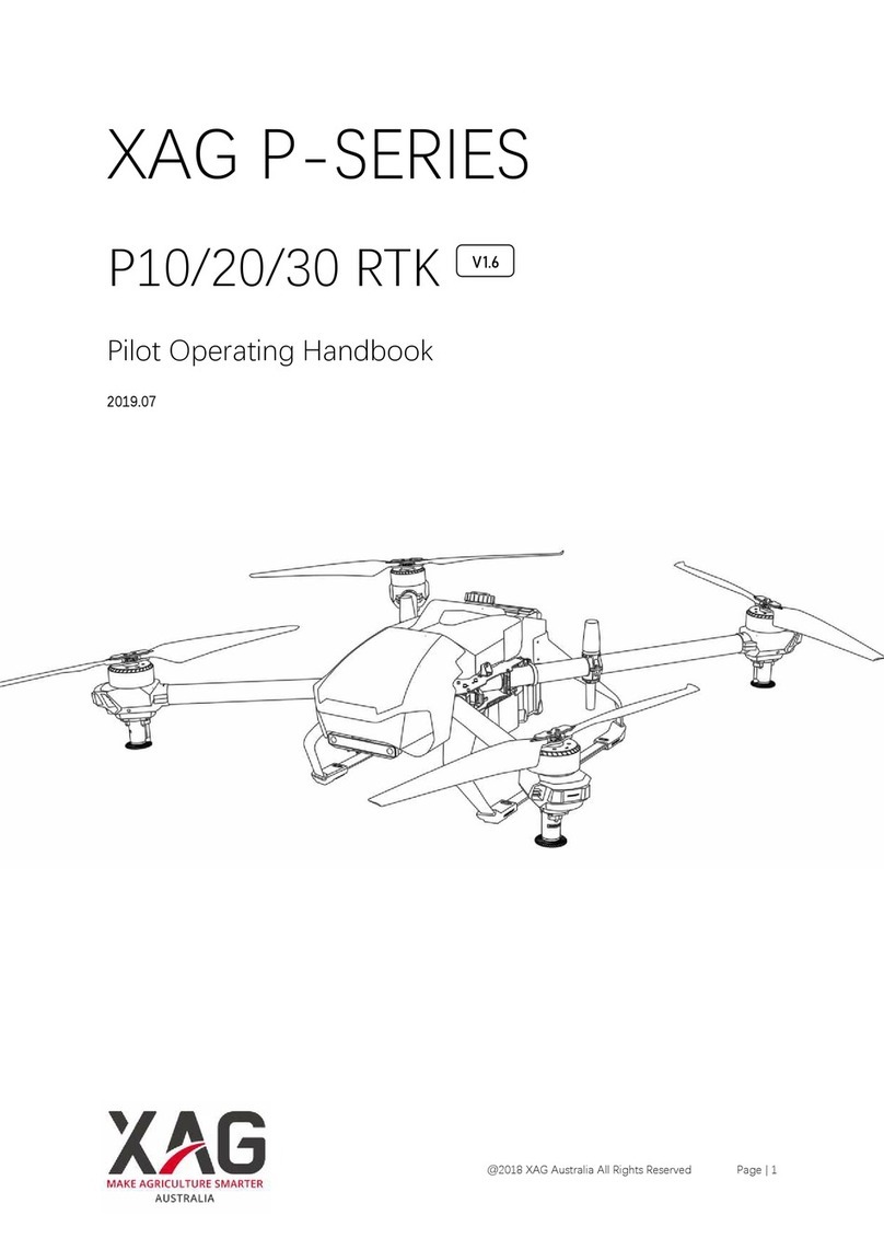
XAG P30 Guide

XAG P30
Aircraft & module maintenance
Version 1.1 EN
AUSTRALIA


3
Dear Customer :
ContaCt Us
To ensure that your aircraft continues to offer optimal performance and to ensure flight
safety, XAG recommends that comprehensive maintenance be performed after every 200
flights or 50 flight hours. This manual is intended to help users maintain their aircraft and
maximize its continued reliability.
After Sales Support: +86 400 980 3131
@2020 XAG Australia All Rights Reserved

4
TABLEOFCONTENT
•Repair Tips
•Propellers
•Nozzles
•Landing Skids
•Motor Housing Protective Pad
•Motors
•Airframe Arms
•Peristaltic Pumps
•Peristaltic Pump Tubes
•Liquid Tank Filter
•Liquid Tank Nozzle
•Liquid Tank Battery
•ESCs
•ESC Board
•Antennas
•Pump Controller Board
•RTK Module
•Comm Module
•Flight Controller
serviCing & r eplaCing
6
7
9
10
12
14
16
22
24
26
27
28
29
30
32
37
39
40
41
@2020 XAG Australia All Rights Reserved

6
Nozzle Indicator / Nozzle Peristaltic Pump to Motor
Payload System Power
Antenna feeder Connector
Repair Tips:
01
Please refer to the following figure as a guide to disconnect connectors:
1. The following connectors are equipped with anti-loosening buckles, please gently press
the buckle before disconnecting the connector.
2. While disconnecting the connector, disconnect the connector and not the wire harness.
Servicing & Replacing Module
Disassembly Tips:
1. Batteries must be removed from the aircraft during maintenance.
2. All liquid must be drained and cleared from liquid tube during maintenance.
@2020 XAG Australia All Rights Reserved

7
Use only XAG approved propellers with your
P30 2019. There are two types of propeller,
CW and CCW as indicated on the Propellers as
figure below.
Propellers
Use a 3.0 screwdriver to remove the 4 screws on the
fastening paddle clamp, then remove the propeller
for replacement.
The screws using M4*12*8 Hexagon socket
combination screw here.
•Motor 1 , & Motor 3 : CCW
•Motor 2 , & Motor 4 : CW
②
L
①
③ ④
R
FRONT
REAR
P30 2018/2019 Propeller-CW *2 SKU-02-006-00070
P30 2018/2019 Propeller-CCW *2 SKU-02-006-00071
M4*12*8 Hexagon socket combination screw *8 SKU-02-004-00227
💡 What do we need in this section:
Reassemble the propeller back in place and tighten
the 4 screws on the propeller clamp.
🛠
🔧Disassemble:
Assemble:
@2020 XAG Australia All Rights Reserved

8
•Check and ensure the CW and CCW Propellers are installed correctly.
•Gently press the propeller blade up and down to check if there is any backlash.
WARNING:
•Be aware of the sharp edges of the propeller and Handle with care.
•Only use XAG approved propellers. Do not mix propeller types.
•ONLY use original XAG propellers for a better and safer flight experience.
•Check and ensure that screws are tighten and secure.
•Ensure that all screws are in good condition before installing. DO NOT use aged, chipped or
damaged screws.
•Check that the propellers and motors are installed correctly and firmly before each flight.
•Ensure that all propellers are in good condition before each flight. DO NOT use aged, chi-
pped or damaged propellers.
•To avoid injury, STAND CLEAR of and DO NOT touch propellers or motors when they are
spinning.
CHECK :
@2020 XAG Australia All Rights Reserved

9
🔧Disassemble:
Nozzles
1. Drain all liquid and residues from
the liquid tube and unplug the
corresponding liquid tube.
Uses a 2.5 screwdriver to remove
the 4 screws securing the Nozzle.
The screws using M3*8*6
Hexagon socket combination
screw here.
2. Disconnect the nozzle connector
and remove the nozzle.
I. Prevent liquid tubefrom bending.
II. Avoid liquid or foreign matter when connecting or disconnecting the nozzle connector .
III. Ensure the shock-absorbing screws are intact and not damaged, DO NOT install with force.
The shock-absorbing screws using M3*8 Screw Dampener here.
•After the reassembly of the nozzle is completed, perform a manual spray test to confirm
the corresponding nozzle is working normally.
IMPORTANT:
P20/P30 2019 Nozzle *1 SKU-05-002-00546
M3*8*6 Hexagon socket combination screw *6 SKU-02-004-00223
M3*8*10 Screw Dampener *10 SKU-02-001-02233
💡 What do we need in this section:
1. Reconnect and secure the nozzle connector, and gently
places the connector back into the Motor Housing Kit.
2. Connect the liquid tube to the Nozzle Inlet .
3. Assemble and fixes the Nozzle in the direction as shown
in the figure.
🛠Assemble:
CHECK :
@2020 XAG Australia All Rights Reserved

10
Landing Skids
•Use a 3.0 screwdriver to remove the fastening screws between the Landing skids and the
Airframe, and take out the hookdown point , nut bars , battery rails , and the landing skids
that need to be replaced.
The screws using M4*16*8 Hexagon socket combination screw here.
•Note: By removing the corresponding screws , the landing skid can be disassembled into
three parts: the front landing skid , the centre landing skid , and the rear landing skid . Only
the damaged part can be replaced.
🔧Disassemble:
P30 2019 Landing Skid (Rear Left) *1 SKU-14-002-00070
P30 2019 Hook Down Point *1 SKU-02-002-03439
P30 2019 Landing Skids Nut Bar *1 SKU-02-002-04244
P20/P30 2019 Battery Rail *1 SKU-14-002-00119
M4*16*8 Hexagon socket combination screw *8 SKU-02-004-00228
💡 What do we need in this section:
The Landing Skids are total of five SKU codes according to different parts.
@2020 XAG Australia All Rights Reserved
11
1. First, install the front section of the landing skids and pre-lock the 3 screws on the landing
skids to ensure accurate positioning before locking.
The screws using M4*16*8 Hexagon socket combination screw here.
2. As shown in the figure, use the battery rail, thehook down point and the corresponding
screws and nut bars to fix the rear of the Landing Skids on to the fuselage .
I. Pre-Check the orientation before installing the battery rail (Guide section should be facing
upward).
II. Before reassembling the Hook down point, ensure that the nut bars are reassemble in place
without protruding.
1. Hook Down Point
2. Nut Bar
3. Rear Landing Skids
4. Battery Rail
Hook Down Point
Nut Bar
Rear Landing Skids
Battery Rail
IMPORTANT:
🛠Assemble:
❶
❷
❸
❹
@2020 XAG Australia All Rights Reserved
12
Motor Housing Protective Pad
1. Disassemble the Propeller (Refer to Propeller Section).
2. Use a 2.5 screwdriver to remove the 4 screws on the Motor Top Housing.
Then, Use a 1.0 screwdriver to remove the remaining screws securing the Spray Disc and
remove the Spray Disc.
3. Use a 2.5 screwdriver to remove the 4 screws securing the Lower part of the Lower part of
the Motor Housing Kit , and remove the Motor Case.
4. Disconnect the Nozzle Indicator Connector , then remove the Nozzle indicator on both
sides. Use a 2.5 screwdriver to remove the 4 screws securing the upper part of the Motor
Housing Kit, and remove the Motor Case.
5. Use a 2.5 screwdriver to remove the 4 screws securing the Motor Housing Protective Pad,
then remove the Protective Padding.
1.Motor Top Housing
2.Motor Housing Kit (Upper Part)
3.Nozzle Indicator
4.Motor Housing Protective Pad
5.Motor Housing Kit (LowerPart)
P20/P30 2019 Motor Housing Protective Pad *1 SKU-14-002-00067
M3*8*6 Hexagon socket combination screw *6 SKU-02-004-00223
M2*6*5 Hexagon socket combination screw *5 SKU-02-004-00319
💡 What do we need in this section:
🔧Disassemble:
❶
❷
❸
❹
❺
@2020 XAG Australia All Rights Reserved

13
1. Reassemble the Motor Housing Protective Pad, upper part of the Motor Housing Kit and
Motor Top Housing in order and tighten the screws to re-secure each component.
2. Reassemble the Nozzle Indicator back into original position.
Reconnect and secure the nozzle indicator connector, and gently pushes the connector
back into the Airframe Arm.
3. Pass the Nozzle Indicator wiring behind the Motor Mount Arm Clamp.
4. Reassemble the Motor Case (Bottom) and Spray Disc in order and tighten the screws to re-
secure each component.
I. Before reassembling, be aware of the screw model and do not miss or reassemble with
wrong screw.
II. Avoid liquid or foreign matter when connecting or disconnecting the connectors.
IMPORTANT:
The screws using 2.5 screwdriver is the M3*8*6 Hexagon socket combination screw here.
The screws using 1.0 screwdriver is the M2*6*5 Hexagon socket combination screw here.
🛠Assemble:
@2020 XAG Australia All Rights Reserved

14
Motors
1. Disassemble the Propeller, Nozzle and Motor
Housing Protective Pad (Refer to Propeller,
Nozzle and Motor Housing Protective Pad
Section).
2. Use a 2.5 screwdriver to remove the 6 screws
securing the Central Compartment Cover,
and disconnect the connectorson the Central
Compartment Cover and gently remove the
cover.
Disconnect the motor connector and draw out
the three-phase wire of the motor from the
Airframe Arm.
3. Use a 3.0 screwdriver to remove the 4 screws
securing the Motor Mount , then remove the 4
screws securing the Motor for maintenance and
replacement.
P30 2019 Motor (Short - Cable) *1 SKU-02-005-00102
P30 2019 Motor (Long - Cable) *1 SKU-02-005-00103
M3*8*6 Hexagon socket combination screw *6 SKU-02-004-00223
M4*12*8 Hexagon socket combination screw *8 SKU-02-004-00227
M4*25*9 Hexagon socket combination screw *9 SKU-02-004-00229
💡 What do we need in this section:
🔧Disassemble:
The screws using 2.5 screwdriver is the M3*8*6 Hexagon socket combination screw here.
The securing the Motor Mount screws using 3.0 screwdriver is the M4*25*9 Hexagon
socket combination screw here.
The securing the Motor for maintenance screws using 3.0 screw driver is the M4*12*8
Hexagon socket combination screw here.
@2020 XAG Australia All Rights Reserved
15
1. Reassemble the Motor, Motor Mount, and Motor Mount Arm Clamp in order and tighten
the screws to re-secure each component. Insert the Motor connector through the
Airframe Arm and reconnect the connector.
2. Inspect and ensure the antenna cord and feeder protective cover are assembled
correctly, then reconnect the connectors on the Central Compartment Cover and
tighten the screws to re-secure the cover.
3. Reassemble the Motor Housing Protective Pad, Nozzle and Propeller in order and
tighten the screws to re-secure each component.
I. Ensure there are no loose or missing screws.
II. Avoid foreign matter scratching the motor wiring.
III. Avoid liquid or stain when connecting or disconnecting the connectors.
IV. After reassembling, inspect and ensure the motor is installed correctly and level.
•After the reassembly of the motor is completed, perform motor idletest and observe if the
XAG Agri APP reports any error.
CHECK :
IMPORTANT:
🛠Assemble:
@2020 XAG Australia All Rights Reserved
16
Airframe Arms
1. Drain all liquid and residues from the liquid tube of the corresponding Airframe Arm.
Remove the Airframe hood and unplug the corresponding liquid tube and antenna cord.
🔧Disassemble:
P30 2019 Airframe Arm Slider (Upgraded) *1 SKU-14-002-00165
P30 2019 Airframe Arm Fastener *1 SKU-14-002-00167
M3*10*6 Hexagon socket combination screw *6 SKU-02-004-00224
M4*12*8 Hexagon socket combination screw *8 SKU-02-004-00226
P30 2019 M3*25*6 Hexagon socket combination screw *6 SKU-02-004-00474
💡 What do we need in this section:
@2020 XAG Australia All Rights Reserved

17
2. Use a 2.5 screwdriver to remove the 6 screws securing the 4G Antenna Mount, and remove
the Antenna Mount.
The screws using M3*10*6 Hexagon socket combination screw here.
•Use a 2.5 screwdriver to remove the 6 screws securing the Central Compartment Cover,
and disconnect the connectors on the Central Compartment Cover and gently remove the
cover and the feeder.
3.
@2020 XAG Australia All Rights Reserved
18
5. Disassemble the Propeller, Nozzle, MotorHousing and Motor.
Gently pull out the corresponding Airframe Arm, and remove the Nozzle Indicator Wiring
Harness, Nozzle Wiring Harness and liquid Tube.
Note: For Arm 3 and Arm 4:
RTK Antenna and 2.4G Antenna also needs to be disassembled (Refer to Propeller, Motor,
and Antenna section) .
4. Use a 2.5 screwdriver to remove the 4 screws securing the corresponding Arm Slider.
Note: For Arm 3 and Arm 4: In addition to the Arm Slider, Airframe Arm Fastener located on
the side also needs to be disassembledby removing the screws .
The screws using securing the corresponding Arm Slider is the P30 2019 M3*25*6 Hexagon
socket combination screw here.
In addition to the Arm Slider the screws using M4*10*8 Hexagon socket combination screw
here.
•Disconnect the motor connector and
draw out the three-phase wire of the
motor from the Airframe Arm.
@2020 XAG Australia All Rights Reserved

19
1. Reassemble the Nozzle Indicator Wiring Harness, Nozzle Wiring Harness, liquid Tube, Motor,
Motor Housing, Nozzle and Propeller in order.
Note: For Arm 3 and Arm 4:
RTK Antenna and 2.4G Antenna also needs to be reassembled.
2. Insert the corresponding Airframe Arm back into the designated position of the fuselage,
then pass the Antenna, Wiring Harness and liquid tube through the Airframe Arm and re-
secure the Arm Slider with screws.
Note: For Arm 3 and Arm 4:
In addition to the Arm Slider, Airframe Arm Fastener located on the side also needs to be
reassemble and re-secured with screws.
3. Re-connect the Central Compartment corresponding connectors of the Motor, Nozzle and
Nozzle Indicators, then reconnect the liquid tube and adjust the length of the liquid tube.
4. Place the Feeder protective padding onto the corresponding position of the Air frame
Central Compartment, reconnect the Central Compartment connectors and tighten the
screws to re-secure each component.
5. Reassemble the 4G Antenna Mount,and tighten the screws to re-secure the component.
Then reconnect the antenna feeder and reassemble the Airframe hood back into the
original position.
I. Ensure there are no loose or missing screws.
II. After reassembly, inspect and ensure the reassembled arm is firmly secured, and all
connectors and antennas are connected correctly.
III. Avoid liquid or foreign matter when connecting or disconnecting the connectors.
IV. During reassemble process, place the feeder in the Airframe Arm then install onto the
Central Compartment and avoid the feeder being damage or scratched during reassembly
process.
V. During reassemble process, be aware and prevent liquid tube frombending and adjust
liquid tube length accordingly.
VI. After reassembly, inspect and ensure the Airframe hood is firmly secured.
Unsecured Airframe hood may fall off and causes accidents during flight.
🛠Assemble:
IMPORTANT:
@2020 XAG Australia All Rights Reserved
20
Airframe Arm (New Model)
1
1
4
3
2
1
4
3
2
•XAG P-Series 2019 have a newer version of Airframe ARM that should be used
in conjunction with Arm Slider.
ARM 1 (SHORT)
Airframe ARM Slider
Airframe ARM
P30 2019 Airframe Arm Slider (Upgraded) *1 SKU-14-002-00165
P30 2019 Airframe Arm (Short) *2 SKU-14-002-00162
P30 2019 Airframe Arm (Long) *2 SKU-14-002-00163
💡 What do we need in this section:
@2020 XAG Australia All Rights Reserved
Other manuals for P30
1
This manual suits for next models
1
Table of contents
Other XAG Drone manuals