9
English
APOLLO 80 - INSTRUCTION FOR INSTALLATION
➠
Connect the concentric pipe sections and any necessary bends;
➠
Fit a clamping strip and silicone sealing ring to every connection;
➠
Secure the clamping strip with a self-tapping screw in places which will be inaccessible after installation;
➠
Use enough brackets to ensure that the weight of the pipes does not rest on the appliance;
➠
Determine the remaining length of the roof duct;
➠
Cut the roof duct to size.
!N.B. Be sure to maintain the correct insertion length.
➠
Connect the roof duct to the concentric pipes.
!N.B. - Make sure the universal roof tile ts well against the surrounding tiles;
- Make sure the adhesive ashing sticks to the at roof properly.
6.5.4 Connection to an existing flue
The appliance can also be connected to an existing flue.
A flexible SS pipe is placed in the chimney for discharging flue gases. The surrounding space is used to supply the
combustion air.
The following requirements apply for connection to an existing flue:
- allowed only if the special DRU chimney connection set is used;
- Installation instructions supplied;
- minimum dimensions 150 x 150 mm;
- maximum vertical length 12 metres;
- maximum horizontal length 3 metres;
- the existing flue must be clean;
- the existing flue must not have any cracks or leaks.
6.6 Building the chimney breast
The appliance is designed to be installed snugly into a newly built chimney breast.
There must be sufficient space around the appliance to ensure a good heat distribution.
The chimney breast should be ventilated by vents.
N.B. - Use incombustible and heat-resistant material to construct the chimney breast, including rear wall of the chimney
breast;
- The total free vent area of the vents, installed as high as possible, should be at least 200 cm2.
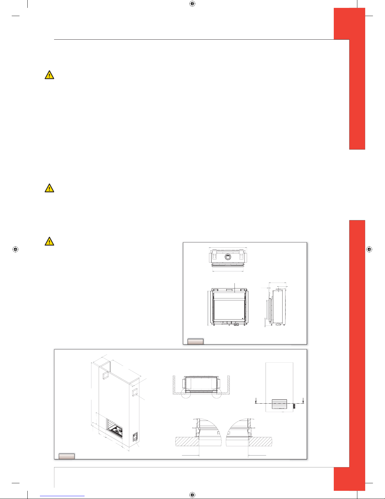
!N.B. When building the chimney breast, the following points should be taken into account (see Fig. 2):
- position of the control box: this should be placed within 850 mm to the left or right of the appliance, as low as possible;
- size of the control box; see section 6.7 Installing the control box;
- position of the vents;
- the size of the glass window so that it can be tted/removed once the chimney breast has been built;
- protecting the gas control block and hoses from cement and plaster.
!Tip The vents should preferably be created in both sides of the chimney breast: you could use DRU ventilation elements.
➠
Check that the concentric system has been installed correctly;
➠
Check that the clamping strips have been secured with self-tapping screws in places which will be inaccessible later;
➠
Allow sucient clearance round the appliance in the chimney breast to enable the heat to disperse:
- minimum internal height: 1350 mm;
- minimum internal width: 1450 mm.
➠
Do not plaster over the anges because:
- the heat from the appliance could cause cracks;
- it will then be impossible to remove/t the glass window.
➠
If the chimney breast is of materials similar to stone, or is nished with plaster, it should be dried-out at least 6 weeks
before commissioning, in order to prevent cracks.
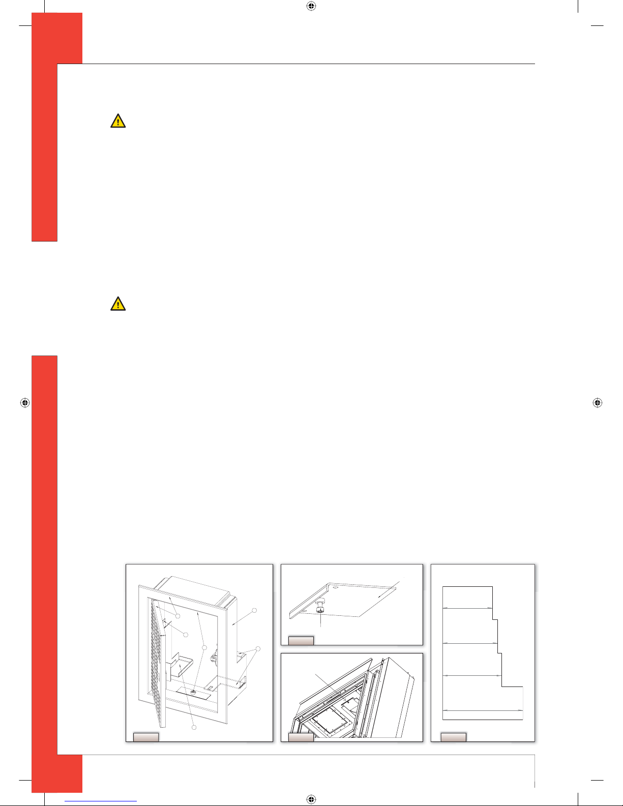
6.7 Installing the control box
The control box is to be installed as low as possible.
The control box contains various components such as the type plate, the gas control block, and the receiver for the
remote control. (See Fig. 5 for details.)
➠
Make a 285 x 194 mm (h x w) opening in the chimney breast;
➠
Fit the inner frame (1); to do this unscrew the bolts (5).
!Tip - If the chimney breast is brick, the inner frame can be cemented in during building;
- For a chimney breast of any other material, glue/cement the inner frame in place or t it with four countersunk
screws.
UK
95901101UK Install_UK.indd 995901101UK Install_UK.indd 9 23-01-2009 09:38:2023-01-2009 09:38:20