DRYDEN AQUA DA-GEN User manual

DA-GEN
Dryden Aqua Generator
Manual
Bedienungsanleitung
Guide d’Installation
Manuale Utente
Manual del Usuario
Gebruikershandleiding
English.................. 1
Deutsch................ 13
Français................ 25
Italiano..................37
Spanish.................49
Nederlands.......... 61
Schemata............. 73
CE-Mark............... 76
EN
DE
FR
IT
ES
NL


DA-GEN
Dryden Aqua Generator
1
2
1
2
3
4
5
3
4
1
2
3
4
5
5
6
5
6
1
2 3
4
1. DESCRIPTION
Control panel Cell
4 Amp fuse for panel and cell
4 Amp fuse relays
The DA-GEN is an innovative water treatment system and additional an intelligent pool controller. The DA-GEN
combines Hydrolysis with Electrolysis with a low mineral content.
The Hydrolysis produces free radicals and other oxygen compounds like ozone, peroxide and persulfate. All
these oxidants destroy organic substances and pathogens in the water. Free radicals are the strongest oxidants
we know. They oxidise and decompose in a few seconds. To guarantee a safe residual disinfection the DA-GEN
produces a very small amount of chlorine. In combination with Dryden DAISY®we need a very low mineral
content of 1 to 2 kg MgCl2or 0.75 to 1.5 kg NaCl per m3.
The DA-GEN also controls all your pool equipment centrally. Thanks to WiFi you can check and control your pool
system 24/7.
110-230 V
Cell
Gas detector connector
Cell connector
Cell housing
Gas detector (internal)1
Connection cell
Gas detector connection
Main 230V connection
ON/OFF switch
USER MANUAL
2. MAIN SCREEN
PLUS key
Modify value/selection
MINUS key
Modify value/selection
OK key
Select/conrm
UP key
Navigation up
DOWN key
Navigation down
RETURN/ESCAPE
key
Current time
Production intensity
in % (normally 40-100%)
Communication display – mother board
Heating ON/OFF
Manual
Automatic
man
aut
Status of ltration relay
(see chapter 12- Filtration)
Automatic measurements: pH/redoX/
free chlorine/conductivity (according to options)
Lights
Manual / Automatic
man aut
Water temperature
Polarity 1 / Polarity 2
Filtration stopped due to lack of water ow
Waiting time
Cover
Pol 1
Flow
Low
---
Pol 2
If the cover is open the ltration speed is “medium” (if with
frequency controlled pump)
Lack of conductivity or salt / low water temperature / scale on
cell / exhausted cell (check working hours)
7.4
7.0
ON/OFF
pH Setpoint
Setpoint pH minimum (if using pH-Minus and pH-Plus)
Function of pH dosing pump
AL3 Maximum dosing time exceeded ( to reset the alarm)
Flow alarm (Paddle/Gas)
700
FL 1
ON/OFF Additional chlorine pump (optional)
Minimum Redox Setpoint
AL3 Maximum dosing time exceeded ( to reset the alarm)
Flow alarm (Paddle/Gas) / Flow alarm rotameter Cl2
AL3
FL 1
0.30
FL 2
Free Chlorine Minimum Setpoint
Maximum dosing time exceeded ( to reset the alarm)
Status of the auxiliary relays
TANK Low level pH-Minus bottle
12:30 25º
man
off
man
off
Cover
Pol 1
LOW
100 %
hydrolysis
pH 7.4 OFF
AL37.0
7.4
Rx
mV
700 OFF
AL3FL1
700
Cl
ppm
0.30 FL2
FL1
0.30
measures
1 2 3 4
TANK
Shortcut Backwash
(press 3s)
Shortcut Light
(press 3s)
1Except DA-GEN 150
1EN

7
2
A
B
1
3
9
13
15
11
4
56
8
C
12
7
3
A
B
C
1
2
4
5
6
8
9
10
11
12
13
14
10
15
14
3. SYSTEM INSTALLATION
* Filtration control by external timer
Filtration mode:
“Manual/ON”
230 V
* Filtration control by internal timer
Filtration mode:
Automatic
see Chapter 12
230 VLINKS TO FILTER PUMP
Paddle ow switch and temperature module
APF®dosing pump
pH dosing pump
pH injection
Prelter
Wi module
APF®
(not included)
pH-Minus
(not included)
If Outdoor pool: ACO®
(not included)
Besgo valve (not included)
External pump controller*
Filter with AFM®
Filter pump
Control Panel
Free chlorine cell with rotameter
Cell
(always in vertical position if installed without paddle
ow switch )
pH probe
Redox probe and/or conductivity probe
Product Maximum
consumption
DA-GEN 24 90 W
DA-GEN 45 125 W
DA-GEN 90 180 W
DA-GEN 150 175 W
Private
Product Maximum
consumption
DA-GEN 240 680 W
DA-GEN 360 1000 W
DA-GEN 500 1020 W
DA-GEN 750 2880 W
Public
Electrical consumption
Use of a 13 Amp time delay circuit breaker is recommended
for private devices and a 16 A breaker for public devices.
In case of sharing the power supply with other devices
please consult a technician in order to dimension a correct
installation.
Variable Rate Pump
To Earth
6
1 2 3
1
1
2
2
3
4
5
6
7
8
1 2 3 4
3
3
4
4
1
1
2
2
4. ELECTRICAL CONNECTIONS
Connection ext. display*
Connection WIFI module
Device control SLAVE
Variable speed pump
*IF connecting 2 displays on
the device, remember not to
connect the second display in
this communication channel.
Use the “ext. Display” socket
instead.
Chlorine probe detector
FL2 (rotameter)
Cover 1& 5
Conductivity probe
Paddle Flow switch
2& 5
FL1
Suction lance pH-
Minus TANK 4& 5
Temperature probe pHredoX
Free chlorine
pH
pH dosing pump
1& 2
AUX 4
Heating control
13 & 14
AUX 3
ACO®
11 & 12
LIGHT
Lighting control
9& 10
AUX 2
Besgo backwash
valve
5& 6
FILTER PUMP
Filtration control
14
12 11
A1 A2
LN
AUX 1
Dosing pump occulation
APF® 3& 4
3black
5brown
6blue
1red
2yellow
3black
1yellow
2transparent
1slow 2medium
3fast 4common
1red 2yellow
3green 4black
3red 4black
1brown 2blue
7& 8
CONNECT ALL THE SENSORS CAREFULLY, A
BAD CONNECTION MAY CAUSE IRREPARABLE
DAMAGE TO THE DEVICE
123
1
2
3
1234567 8 9 10 11 12 13 14
DRY CONTACT110-230 V max. 3.15 A
2EN

1
2
3
Adjust the alkalinity between 100 and 200
ppm.
Adjust the pH to 7.4.
Adjust the chlorine between 0.1 and 0.5
ppm.
5. INITIAL WATER ADJUSTMENTS
1
2
We recommend to add 1 to 2 kg magnesium chloride (MgCl2) or 0.75 - 1.5 kg
of normal salt (NaCl) per m3of water. The TDS should be at around 1200. It is
recommended to mix them, for example in a ratio 1:3 (MgCl2:NaCl).
Add the magnesium chloride or salt directly to your swimming pool and let the
system run.
In outdoor pools it is necessary to use ACO®.
Water adjustments Adding activator/salt to the water
Attention: Do not calibrate free chlorine with a chlorine
level of less than 0.3 ppm free chlorine!
6. SYSTEM SETTINGS
6.8 6.96.6 6.7
6.1 6.3 6.46.2 6.5
6.12 6.14
6.136.116.10
2x
6.9 Sound
6.11 Password: Protect the user´s menu by activating a password.
To enter your password press a combination of 5 keys and the
system will memorise them. If you forget the password, there is a
“master password”. Ask your installer/provider.
6.3 Language
6.5 Date and Time
6.7 Display brightness
6.12 Hydrolyse-Cell working hours
6.14 System info: Information about
the software versions and the ID node
7. PADDLE FLOW SWITCH
1
2
3
4
5
6
7
8
Connect as shown in the image
and contact your installer for
activation.
Paddle Flow switch FL1 2& 5
Paddle ow switch. Stops
the hydrolysis and the
dosing pumps if there is
no water ow.
8. SUCTION LANCE (pH BOTTLE)
3
4
5
6
Connect the suction lance. The installer/provider
should be contacted to activate the sensor.
pH-Minus bottle
level TANK
4& 5
9. HYDROLYSIS
9.1 9.3
9.2
9.1 Hydrolysis: Programming
of hydrolysis functions
9.2 Level:
Hydrolysis - Desired disinfection
production (Always 100%).
9.3 Mode: If the device has Free Chlorine
and redox probes, choose the parameter
that controls the cell’s chlorine generation.
3EN

10. MEASUREMENTS
10.1 pH Calibration
10.1 10.2 10.3 10.1 Measurements: Adjustment of setpoints and measuring probes.
10.2 Setpoints for each measurement.
10.3 Setpoints:
pH: 7.0-7.4; redox: 600 - 800 mV; free chlorine: 0.1- 0.5 ppm; conductivity:
~ 2000 μS
10.12 10.1310.11
10.14 10.15
pH
10.11 Calibration of pH probe: Recom-
mended at least every 2-3 months during the
usage season. Calibrate it always rst with
the Buffer (2pt).
10.12 Calibration with buffers (buffer pH7 /
pH10 / neutral): Follow the instructions that
appear on the display.
10.14 Manual calibration: Allows
manual adjustment of the probes – only
recommended to correct small deviations in
the readings.
10.15 Without removing the probe from the
water, use the plus/minus keys to adjust the
reading so it matches your reference value
(photometer or other measurement).
10.2 Temperature calibration
10.21 10.22
1 2 3
10.22 Temperature calibration: To set the difference
between the measured value of the probe and the actual
temperature, use the plus/minus and up/down keys.
Set to the actual temperature of the probe and press OK.
Temperature module
Temperature
probe
1
2
3
red
yellow
black
pH module
10.3210.31 10.33
10.3510.34 10.36
10.3 Free Chlorine calibration
10.37 10.38
1
2
3
4
1
2
3
4
5
6
7
8
Free Chlorine control
10.31 Calibration of the Free Chlorine probe:
Recommended at least every 2 to 3 months
10.32 Calibration with buffer (photometer DPD1): Follow
the instructions in 6 steps that appear in the display.
10.33 Step 1 of 6 - Calibrate Cl at 0 ppm (offset): Close
the water ow through the probe and wait for 5 to 60 min
until the reading is close to 0. Press OK
10.34 Step 3 of 6 - Calibrate Cl: Set the water ow to
the correct rate of 80-100 litres/hour. Wait for 5 to 20 min
until there is a stable ppm reading. Press OK.
10.35 Step 5 of 6 - Establish the real ppm values with the
plus/minus keys according to your DPD1 (free chlorine)
value
10.36 Step 6 of 6 - If this screen is not shown repeat the
calibration process.
4.38 Manual calibration: Open the water ow and set the
owmeter (rotameter) to the correct owrate (50-100l/h).
Wait until the current level is stable. Set the chlorine level
with the plus/minus keys, manually (use a manual DPD1
test kit). Press OK when value is correct.
Free Chlorine probe
red black
3 4
Chlorine probe detector
FL2 (rotameter)
3
5
6
black
brown
blue
If using a Variable Speed
Pump, calibrate the probe
using the lowest ltration
speed.
Attention: Do not calibrate if the free chlorine
level is below 0.3 ppm!
4EN

10.4 Redox Calibration
10.44 10.45
redoX
10.4310.4210.41
The redox value shows the oxidation/reduction potential and is used to determine the sterility of the water. Adjusting the ideal redox level (setpoint) is the last step in the
system start up sequence.
Redox control
10.41 Calibration of the redox probe:
Recommended at least every 2 to 3 months.
10.42 Calibration with buffer (buffer
solution 465 mV): Follow the instructions
that appear on the display
10.44 Manual calibration:
Not recommended!
10.5 Conductivity calibration
10.52 10.5310.51
10.54 10.55
1
2
Metering and control of the
conductivity of the water in μS
Optional Conductivity probe 10.51 Calibration of the Conductivity probe:
Recommended every month during usage season.
10.52 Calibration with buffer (buffer solution 1413 μS/
12880 μS/ neutro): Follow the instructions in 7 steps that
appear in the display (screen 4.24 corresponds to step 1).
10.54 Manual calibration:
Not recommended!
Conductivity probe
1yellow
2transparent
11. VARIABLE SPEED PUMP
11.1 11.2
11.4
11.3
110-230 V max. 3.15 A POTENTIALFREIE KONTAKTE
12 3 45 6 78 9 10 11 12 13 14
14
12 11
A1 A2
LN
11.1 Variable Speed Pump: To install a Variable Speed Pump
contact your installer.
11.2 - 11.5 After connecting the pump, each ltration period
can be assigned a different speed
F: fast, M: medium and S: slow.
See chapter 12 - Filtration
11.5 Filter cleaning: To backwash the lter with a Variable
Speed Pump use the fastest speed.
See chaper 13 - automatic backwash
FILTER PUMP
Filtration control
7& 8
Variable Speed Pump
1slow 2medium 3fast 4common
1000 TDS ≈1800 μS
Attention: Use only gold redox probes!
Please see the wiring schemata in the appendix!
5EN

12.1 Manual mode
12.11 12.12
110-230 V max. 3.15 A DRY CONTACT
14
12 11
A1 A2
LN
1 2 3 4 5 67 8 9 10 11 12 13 14
12.11 Filtration:
Conguration control of the lter pump. To set, select
Filtration and conrm by pressing OK. The mode selection
is done in Mode line with the plus/minus keys.
12.12 Manual:
Manually turns ON/OFF the ltration process. No timing
or additional functions. The State (Status) line indicates
whether the ltration pump is ON.
Filter Cleaning: See chapter 13
FILTER PUMP
Filtration control
Setup and connection of a Variable Speed
Pump, see section 11 - Variable Speed Pump
7& 8
12. FILTRATION
12.2 Automatic mode
12.21
In this mode the ltration is controlled by up to 3 timers.
We hardly recommend to run your system in a 24/7 mode with a variable speed pump.
For example: During the night time (6:00 until 24:00 & 0:00 until 10:00) in low speed, during day time (10:00 until 6:00) in medium speed.
To set the ON/OFF times select with the up/down keys in the timer line you want to change (1-3 ).
The plus/minus keys open the selected start time eld. Set the time with plus/minus keys. Scroll with the up key to the minute eld and set it up with
plus/minus keys. To conrm press OK and to cancel press return/escape.
Backwash: See chapter 13
12.21 Automatic
13. AUTOMATIC BACKWASH
13.1 Backwash Mode with Besgo Valve: The DA-GEN is congured for automatic backwash with Besgo. Use AUX 2!
• Mode: Choose Auto
• Start: Choose starting time
• Interval: Set backwash time in seconds (Recommendation: min. 240 seconds with AFM®, min. 300 seconds with Sand)
• Freq.: Choose frequency (at least weekly)
• Shortcut: Enable/Disable Shortcut for manual backwash
13.1
14. LIGHTING
14.4 14.5
14.1
LIGHT
Lighting control
9& 10
14.2 14.3 14.1 Lighting
14.2 Manual Mode (ON/OFF). You can activate
the light also by pressing the short cut. You can
set a timer, after that the light will go out.
14.3 Automatic Mode: Switches lights according
to timer settings. Additional you can switch the
lights on by pressing the Shortcut button
14.5 LED spotlight: In case of installallation of RGB LED lights in the
pool, you can change the color of the lights in the pool. Select the length
of time in seconds in Pulse length and then press Next Program option
to apply the pulse. Refer to your LED spotlight manual to set its different
colors.
Only with an external pump controller unit
Without an external pump controller unit
1 2 3 4 5 67 8 9 10 11 12 13 14
110-230 V max. 3.15 A DRY CONTACT
6EN

15.315.1 15.2
15.8
15. WIFI SETTINGS
15.1 Internet: Once the WiFi module is connected, restart the unit. The internet option will appear in the settings menu.
15.2 WiFi: Select WiFi to scan the available networks accessible to the module. The search will be done automatically.
15.3 Select the desired network accessible to the WiFi module.
15.4 Enter the password in the pop-up keyboard. Scroll up and down with the up/down keys and left to right with the plus/minus keys. To select a letter press OK.
15.5 Enter AP: If you do not nd your Network in the automatic mode, then you can enter the network name manually. Check rst if the network works on other devices.
15.6 Conguration: For a more detailed conguration enter this menu or contact your installer.
15.8 Status: Check the status of your connection.
15.9 Test connection: Check if your connection has been successfully established.
Once the WiFi module is connected to the network with both lights ON, enter in www.DA-GEN.com. Access the Register option and enter all the data requested.
15.10 - 15.13 The system node ID that you will need for the registration progress is located under System settings > System info > Power module
Upon completion of the process, you will have total control of your pool, will be able change parameters such as setpoints, ltration hours and turn ON/OFF any auxiliary relays.
Connection
WIFI module
Green LEDs
(ON)
1red 2yellow
3green 4black
15.9
3
4
5
6
7
8
Cover 1& 5
15.4
17. COVER
17.1 17.2
15.5
15.10 15.11 15.12 15.13
17.1 Cover: If the DA-GEN is runned with a frequency controlled pump and if it is connected
to the pool cover, the ltration speed will automaticly go to «medium» when the cover is
opened. (Please check the ltration speed in Chapter E). Set the Reduction value to 0%!
How to install: If the cover is open, the contact has to be closed and vice versa
7EN

AUX 2 5& 6
Automatic
backwash valve
(Besgo)
AUX 1 3& 4
APF®dosing pump
18.3
18.6
18.4 18.5
18.7
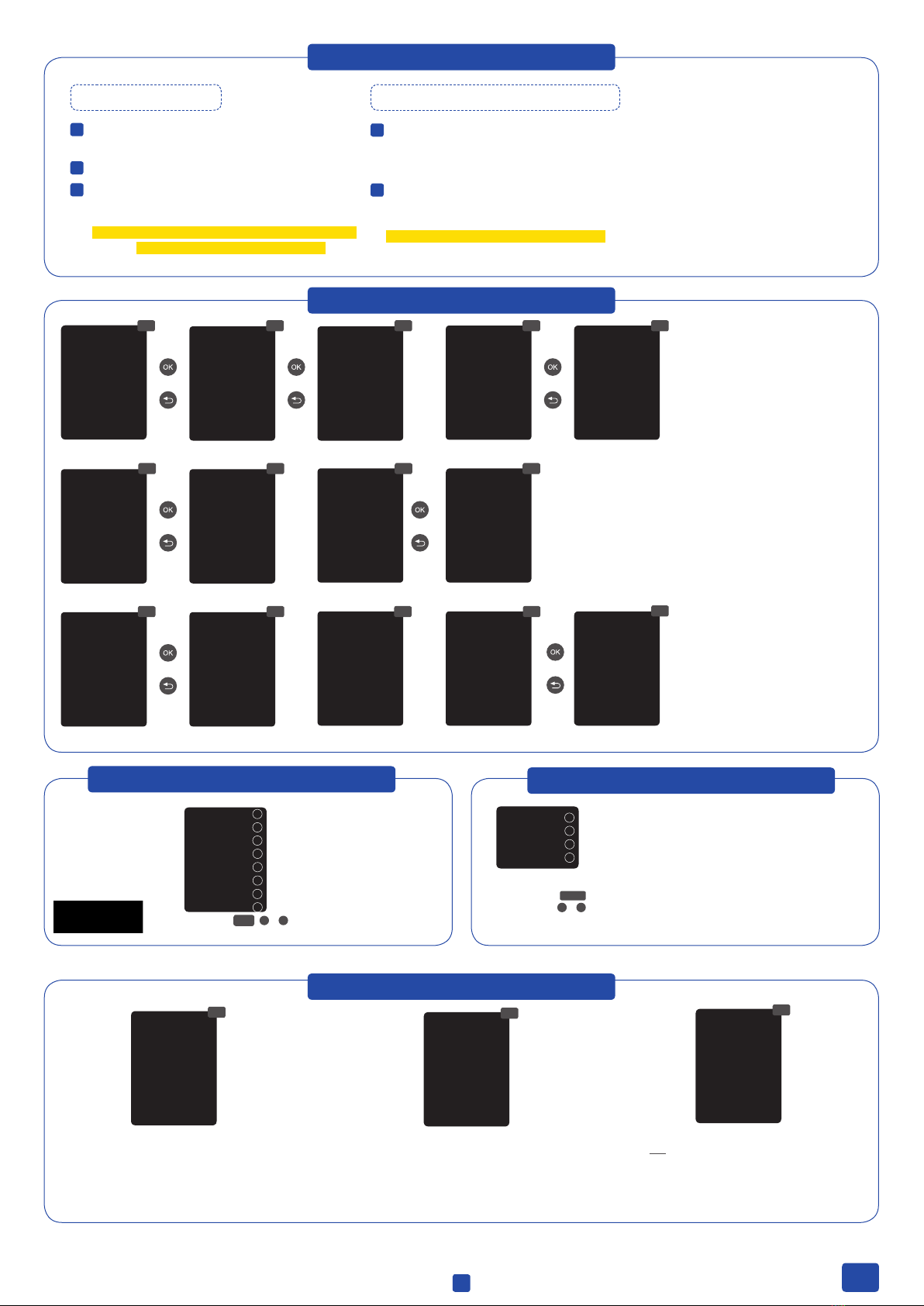
18. AUXILIARY RELAYS
18.218.1
ACO®
11 & 12
110-230 V max. 3.15 A DRY CONTACT
1 2 3456 78910 11 12 13 14
AUX 4
Heating control
13 & 14
18.2 It is possible to control up to 4 extra auxiliary
relays (water attractions, dosing pumps, etc).
In default setting you will only see two available
relays: APF® and ACO®: (AUX 1 and 3). AUX 2 is
reserved for the Besgo Valve and AUX 4 for the
heating and therefore not shown here. If you do
not have a heating, you can deactivate it (Chapter
C & D in the service manual) and you will get a
additional free relay (AUX4).
18.3 Manual mode (ON/OFF).
18.4 Automatic mode: ON/OFF according to a timer that adjusts the start and
end of the program. The timers can be congured with a frequency.
18.5 Timer mode: Working time is programmed in minutes. Each time
the Shortcut on the front panel is pressed, it will start up and run for the
programmed time. This function is recommended for timing of air pumps of
spas.
18.7 Rename relays: It is posible to rename each auxiliary relay to suit the use
you want to assign. By pressing the plus/minus keys, a pop-up keyboard will
appear. Scroll up and down with the up/down keys and left to right with the
plus/minus keys. To select a letter press the OK.
The auxiliary relays are congured by default.
If you want to reassign the relays for other
accessories, you must access the “Service
Menu”.
Contact your authorised installer.
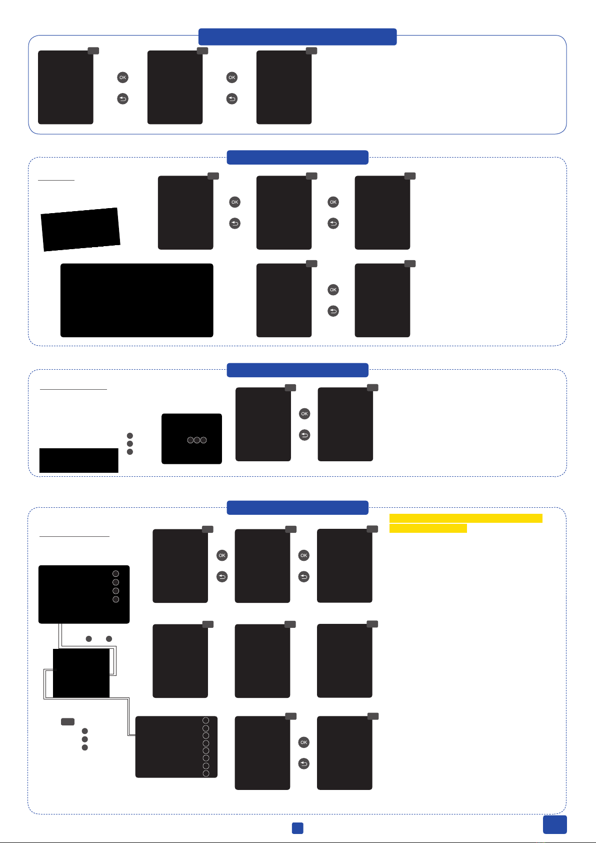
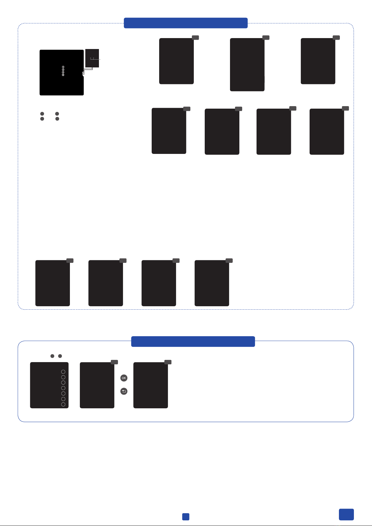
19. MAINTENANCE
If necessary, carry out a monthly visual inspection. To clean the cell:
Stop the system and close the valves
Place the cell for no more than 10 minutes in 3% hydrochloric acid or put it for 2 to 4 hours in normal vinegar.
Once the incrustations have softened remove with a hose to complete cleaning the cell.
DO NOT USE METALLIC OR SHARP OBJECTS TO REMOVE INCRUSTATIONS. Scratching the edges or surface of the cell will make it
vulnerable to chemicals, deteriorate the cell and invalidate the guarantee.
The pool must be vacuumed as usual and the skimmers emptied whenever necessary.
FILTER BACKWASHING: At least once every week for 4 to 5 minutes.
VERY IMPORTANT: Make sure the cell is off while cleaning the lter. If the system controls the ltration pump, use the option “backwash” of the programmed ltration
mode. See chapter 13 - automatic backwash
Check regularly the level of your pH and APF®bottle to prevent the dosing pump from running dry.
pH / Redox / Conductivity – probes: The probes must be cleaned and recalibrated every 2 to 3 months. To clean the probe insert in
electrode cleaner. After each clean the probes must be re-calibrated.
Attention: the probes should never dry out and must be kept wet if stored (when emptying the pool for winterising, make sure
to store the probe head in water).
~1200 ppm TDS/mS
~2000 μS
Visual inspection to detect incrustations.
SALT CONCENTRATION: HYDROLYSIS CELL:
1
1
2
2
3
3
4
Cleaning the Cell
General maintenance
Monthly checks
8EN

20. TROUBLESHOOTING
•If the salt concentration is correct (1- 2 kg/m3 MgCl2or 0.75 - 1.5 kg/m3NaCl): The cell is reaching its end of life. As of this moment check the intensity every 15-20 days.
•When polarity 2 does not reach intensity of Polarity 1, we recommend substituting the cell for a new one if it happens during the summer period. If it happens during winter,
change the cell before the next summer period.
Polarity 1 reaches maximum intensity, but polarity 2 (auto clean) does not reach maximum intensity
•Check if ON/OFF switch is illuminated.
•Check the connection wire between display and motherboard.
•Check the 3.15 A fuse of the device – it could have tripped due to overload.
•Check the power supply – 230V/50Hz.
•If the problem persists contact TECHNICAL SERVICE
•Lower hydrolysis cell intensity.
•If your system includes automatic Redox control, check the Redox setpoint value.
Reduce it by 50 to 100 mV.
•If your system includes free chlorine measurment, adjust the setpoint value.
•Check redox probe and calibrate it if necessary.
•Check the free chlorine probe and calibrate it.
Blank display Excess of chlorine in the water
•Attention: At 1200 TDS, 50 - 80% and the warning “LOW” is normal
• Low water temperature.
•Check the salt concentration (TDS) in water.
•Check the cell status (it may be incrusted or calcied).
•Clean the cell according to the instructions in section 19.
•Check that the cell is not worn out (remember that the cell is guaranteed for
5,000 hours, approx. 2-3 years of summer usage).
Hydrolysis does not reach the setpoint value
•Very hard waters with a high pH and total alkalinity: balance water adjusting pH
and total alkalinity.
•Check to ensure that the system automatically changes polarity approximately
every 300 minutes.
•Consult with our technical service to consider accelerating the polarity change
(auto-cleaning) . WARNING: Accelerating the polarity change decreases the cell
life (5,000 hours) proportionally. Don’t go below 200 minutes!
Cell incrusted in less than 1 month
•Check gas and paddle ow detector cable.
•Clean for incrustations of the paddle ow detector at the top of the cell housing.
•Check to see if system is free of air (gas detector must always be submerged).
•Metallic elements lack standardised earth connection. Contact an electrician to
solve the problem.
•Rusted components are not stainless steel (minimum 316/V4A/1.4571).
•The salt concentration (TDS) is too high.
•Attention Stainless Steel parts must be cleaned regularly
Hydrolysis display shows FLOW Rust on metallic components in the pool
WARNING
Keep chemical levels in pool as instructed in this manual.
CLEANING FILTER
Very Important: Make sure the cell is off while cleaning/backwashing the lter. If the system controls the ltration pump, use the option “lter cleaning” of the programmed
ltration mode. See section 5 – Filtration / Filter Cleaning of the General Installation Guide.
VERY IMPORTANT
Remember that the system needs some time to adapt to your pool (up to 14 days)!
SECURITY
To avoid accidents, children should not handle this product unless supervised by an adult. Children should be supervised at all times when in or near a spa, pool or jacuzzi.
HANDLING AND DOSING DANGEROUS CHEMICALS
Chemicals should be handled with extreme caution. When preparing acid, always add acid to water, never add water to acid, because very dangerous gases may be produced.
•Increase the ltration hours to 24 hours
•Increase the hydrolysis level (to 100%).
•Increase the salt concentraion (TDS) in the water. Setpoint app. 1200 ppm.
•In an outdoor pool: Add ACO®to the water.
•Check if the reagents in test kit are in date.
•Check if the temperature or number of users has risen.
• If you want a higher chlorine level you have to increase the salt concentration.
Attention: Higher risk of corrosion!
Free chlorine level doesn’t reach the setpoint
•The maximum dosing time (standard 999 min.) is accomplished and the pH-
Minus dosing pump stops in order to avoid the acidication of the water.
•To delete the message and to restart the metering press ESC ( ). Do the
following verications in order to preclude errors on the device: Verify if the pH
probe reading is correct (if not, calibrate the probe or substitute it with a new
one); Verify if the acid/base reservoir is full and if the dosing pump is working
correctly; Verify the variable speed of the dosing pump.
Alarm AL3 and pH dosing pump stopped
Dosing pump is not working properly
21. IMPORTANT NOTES
•Check fuse on the right side of the dosing pump
• Check (and change) the dosing speed
• Check electrical connections
• Check tubes and ttings for leaks
• Check if injection valve is blocked
• Check if suction lance/suction weight is blocked
• Check if error message «TANK» appears. If yes replace bottle, if not check the
polarity of the suction lance or replace the suction lance
9EN

DA-GEN
Dryden Aqua Generator
B.2B.1 B.3
C.1
Accessing the Service Menu:
B.1: Main screen (according to model)
B.2: Select System Settings
B.3: Select Service Menu
B.4: Enter password
C.1 The 7 available relays
can be hooked up to various
predened external devices
being controlled by the unit.
Note: “NO” will deactivate the predened
parameters and leave the relay available.
C.2 The predened functions are:*
pH: Acid pH-pump.
Filter: Filtration pump.
Light: Pool lights.
AUX 1: APF®
AUX 2: Besgo Valve
AUX 3: ACO®
AUX 4: Heat pump or other heating device.
* Recommended relay settings.
B.4
C.2
B) SERVICE MENU
C) RELAY CONFIGURATION
SERVICE MANUAL
PASSWORT MENU INSTALLATEUR:
123
1
1
2
2
3
4
5
6
7
8
1 2 3 4
33 3
3
44 4
4
11 1
1
22 2
2
A) ELECTRICAL CONNECTIONS
Connection remote display*
Connection WIFI module
Device control SLAVE
Variable speed pump
*In case of connecting 2
display´s on the device,
remember not to connect
the remote display in this
communication channel. Use
the “Extern” channel instead.
DRY CONTACT110-230 V max. 3.15 A
Chlorine probe detector
FL2 (rotameter)
Cover 1& 5
Conductivity probe
Flow switch FL1
2& 5
pH-Minus deposit
level TANK 4& 5
Temperature probe pHredoX
Free chlorine
pH
pH dosing pump
1& 2
AUX 4
Heating control
13 & 14
ACO®
11 & 12
LIGHT
Lighting control
9& 10
AUX 2
Besgo backwash
valve
5& 6
FILTER PUMP
Filtration control
14
12 11
A1 A2
LN
AUX 1
Dosing pump occulation
APF®
3black
5brown
6blue
1red
2yellow
3black
1yellow
2transparent
1slow 2medium
3fast 4common
1red 2yellow
3green 4black
3red 4black
1brown 2blue
7& 8
CONNECT ALL THE SENSORS CAREFULLY, A
BAD CONNECTION MAY CAUSE IRREPARABLE
DAMAGE TO THE DEVICE
ASK YOUR SUPPLIER OR POOL
BUILDER
1234567 8 9 10 11 12 13 14
10 EN

D.1 D.2 Parameters related to external devices
Range Dimension Standard
factory value Description
0...4 1 (
Redox)
3
(Free chlorine)
0 - FL1 Lack of water ow - It turns off only the cell.
1 - FL1 Lack of water ow - It turns off everything (cells, pumps,...)
2 - FL2 Lack of water ow - It turns off only the cell.
3 - FL2 Lack of water ow - It turns off everything (cells, pumps,...)
4 - FL1 & FL2 If both detected no water ow, it turns off everything (cells, pumps,...)
0...2 1
Congures stops/starts of the hydrolysis cell and auxiliary disinfection pump on Relay AUX 2
according to redoX reading.
0 - Without redoX/CL2(hydrolysis cell is always ON) - Auxiliary disinfection pump is controlled
by redoX/free chlorine CL2.
1 - With redoX/CL2(redoX/free Cl set point stops/starts hydrolysis cell) - Auxiliary disinfection
dosing pump is activated if redoX falls more than 2% lower than set point.
2 - With redoX/CL2(redoX set point stops/starts hydrolysis cell) - Auxiliary free chlorine dosing
pumps are controlled via time delays of parameters 8 and 9.
0...999 Minutes 300 Polarity 1 of hydrolysis cell. (Same as 6)
0...999 Minutes 300 Polarity 2 of hydrolysis cell. (Same as 5)
0...5 Minutes 1 Dead time hydrolysis cell. (Min. 1 min)
0...2 1
0 - Acid and base are activated – controls 2 relays: relay pH and relay AUX 1.
1 - Only controls Acid: Relay pH.
2 - Only controls Base: Relay pH.
0...1 1 0-Temperature is not shown.
1-Temperature is shown in display if the temperature probe is connected.
0...1 1
0-The Temperature probe does not control the heating relay. The relay AUX4 can be used as
“auxilary relay”.
1-The Temperature probe controls the heating relay.
2 - Maximum and minimum temperature controls the heating connected to Relay AUX 4,
allowing the cooling and heating of the pool.
3 Flow mode select
RW Val: 1 0001
4 Hydrolisis mode
RW Val: 1 0001
5 Hidro pol 1 time
RW Val: 300 012C
6 Hidro pol 2 time
RW Val: 300 012C
7 Hidro dead time
RW Val: 1 0001
10 pH setpoint mode
RW Val: 1 0001
14 Show/use temperature
RW Val: 1 0001
15 Heating
RW Val: 1 0001
D) SERVICE SETTINGS
E.2 With the plus/minus keys, select
the pump type connected to the system
(the default is a standard pump type).
The conguration allows the control
of two different variable speed pumps
(Variable Speed A or Variable Speed B).
In case of a variable speed pump (A or
B), establish the speed when the cover
is closed, when the pool heating is
connected and/or it controls a backwash
lter (Besgo).
E.3 Variable Speed Pump A (Hayward® or similar):
During the ltration periods, the corresponding relay
closes. The ltration pump opens and closes contacts
depending on the speed:
Common + 1 – Slow speed
Common + 1 + 2 – Medium speed
Common + 1 + 2 + 3 – Fast speed
Variable Speed Pump A B (Speck® or similar): During
the ltration periods, the corresponding relay closes.
It’s necessary to connect a wire from the ltration relay
to the common. The ltration pump opens and closes
contacts depending on the speed:
Common + 1 – Slow speed
Common + 2 – Medium speed
Common + 3 – Fast speed
E.1 E.2 E.3
E) TYPE OF PUMP
Attention: The faster the polarity change, the
shorter is the life time of the cell! The life time
guarantee will expire.
Consult the wiring-schemata in the appendix!
11 EN

I.1
K.1
I.2
K.2
I.2 Node addr: Used for the conguration of more than 2 user interfaces.
For normal operation of the system, keep the value to 1 for this parameter.
K.2 Server control and connection port in case there is WIFI Module connected to the system.
For the proper functioning of the system, do not change the default values unless you receive a notice from your provider.
F.10 You can associate the level sensor (TANK) to the pH or chlorine (rX). This menu corresponds to the behavior of
the system after the TANK signal activation (acid deposit level TANK).
Ignore – TANK is not shown in the display
Inform – When the sensor detects that the level is low, the TANK alarm is displayed.
Force stop – When the sensor detects that the level is low, the TANK alarm is displayed and the associated dosing
pump stops.
F.1 F.2 F.3 F.2 There are 2 modes for the pH dosing pump:
F.3 Normal: Delay - Delay time between detection of
incorrect value and the start of dosing.
F.4 Repetitive: With the two timers you can programm the
ON and OFF time of the dosing pump
F.6 Other pumps: With the two timers you can programm
the ON and OFF time of the dosing pump
F.8 It corresponds to the behavior of the system after AL3
activation:
Ignore – AL3 is not shown in the display.
Inform – After the selected interval, the AL3 alarm is
displayed.
Force stop – After the selected interval, the AL3 alarm is
displayed on the display and the dosing pump stops. To
reset the alarm and the dosing pump, press .
F) DOSING PUMPS
I) CONNECTION
K) WEB IP
F.6F.5 F.7 F.8
H.2 Reset counters: There are two levels of working hours counters which log the
working hours of the components and devices.
In this service menu the installer can reset the working hour counters on the rst
level (for example when a new cell is installed).
The second level of the working hour counters can only be accessed by the factory.
H) COUNTERS
H.1 H.2 H.3
G.2 Gas (0) - The FL1 alarm is only activated by cell’s gas sensor (external ow switch annulled).
Siempre ON (1) - The FL1 alarm is never activated (invalidates cell’s gas sensor and external ow switch);
Paddle (2) - The FL1 alarm is activated by external ow switch (gas sensor annulled).
Paddle or gas (3) - When both cell’s gas sensor and external ow switch are connected, and either of them detects lack of
ow, The FL1 alarm is activated. To connect the external ow switch use the FL1 terminal
Paddle + Gas (4) - When both cell’s gas sensor and external ow switch are connected, and both of them detects lack of
ow, The FL1 alarm is activated. To connect the external ow switch use the FL1 terminal
Paddle delay - Delay before FL1 is activated
Relay control through ow detection - Manage the FL1 alarm deactivation in case of lack of ow. Recommended option
for oculant dosication or similar.
G.1 G.2
G) EXTRA SETTINGS
F.4
F.10F.9
12 EN

DA-GEN
Dryden Aqua Generator
1
2
1
2
3
4
5
3
4
1
2
3
4
5
5
6
5
6
1
2 3
4
1. BESCHREIBUNG
Elektronikbox Zelle
Sicherung für Gerät und Zelle 4 A
Sicherung Relais 4 A
Der DA-GEN ist nicht nur ein äusserst innovatives Wasseraufbereitungssystem sondern kann zusätzlich auch
als intelligente Steuerung für ihr Schwimmbecken eingesetzt werden. Der DA-GEN kombiniert Hydrolyse mit
Elektrolyse bei äusserst geringem Mineralgehalt. Die Hydrolyse spaltet H2O-Moleküle in Wasserstoff- und
Sauerstoffverbindungen (freie Radikale). Freie Radikale sind die stärksten Oxidationsmittel die wir kennen. Sie
oxidieren organische Stoffe und Krankheitserreger im Wasser komplett, aber zerfallen in wenigen Sekunden.
Um eine Depotdesinfektion im Becken sicherzustellen, produziert der DA-GEN eine kleine Menge an Chlor. Dafür
brauchen wir in Kombination mit DA-SY®nur einen minimalen Mineralgehalt: 1 - 2 kg MgCl2pro m3oder 0.75 -
1.5 kg NaCl. Der DA-GEN steuert zentral alle Ihre Poolkomponenten. Dank WIFI können Sie ihr DA-GEN bequem
24/7 überwachen und steuern.
110-230 V
Zelle
Kabel Gaswächter
Zellenanschluss
Zellenhalterung
Gaswächter (intern)1
Anschluss Zelle
Gaswächteranschluss
Einspeisung 230 V
Ein/Aus
BEDIENUNGSANLEITUNG
2. HAUPTBILDSCHIRM
PLUS Taste
Änderung Wert/Auswahl
MINUS Taste
Änderung Wert/Auswahl
OK Taste
auswählen/bestätigen
AUF Taste
Navigieren nach oben
AB Taste
Navigieren nach unten
ZURÜCK/
AUSTRITT Taste
12:30 25º
aut
on
aut
off
Cover
Pol 1
LOW
100 %
Hydrolyse
pH 7.4 OFF
AL37.0
7.4
Rx
mV
700 OFF
AL3FL1
700
Cl
ppm
0.30 FL2
FL1
0.30
Mesures
1 2 3 4
TANK
Aktuelle Zeit
Produktionsintensität
in % (Zwischen 40 und 100)
Kommunikation Display – Hauptplatine
Heizung ON/OFF
Manuell
Automatik
man
aut
Status Filtrationsrelais
(siehe Kapitel 12 - Filtrierung)
Automatische Messungen pH / Redox /
Freies Chlor / Leitfähigkeit (je nach Optionen)
Beleuchtung
Manuell / Automatik
man aut
Wassertemperatur
Polarität 1 / Polarität 2
Filtration gestoppt wegen fehlendem Wasserdurchuss
Wartezeit
Cover
Pol 1
Flow
Low
---
Pol 2
Wenn Abdeckung geöffnet -> Filtrationsgeschwindigkeit
Medium (wenn frequenzgesteuerte Pumpe angeschlossen)
Fehlen von Leitfähigkeit / niedrige Wassertemp / Zelle
verkrustet / Zelle verbraucht
Anmerkung: Der DAGEN wird mit bis zu 50% tieferem Mineralgehalt betrieben. Daher ist die Meldung
«Low» und eine maximale Produktionsleistung von 50% nicht ungewöhnlich
7.4
7.0
ON/OFF
Sollwert pH
Sollwert pH (bei Regelung mit pH-Minus und pH-Plus)
Funktionseinstellungen der pH-Dosierpumpe
AL3 Maximale Dosierzeit überschritten ( um den Alarm zurückzusetzen)
Durchussalarm
700
FL 1
ON/OFF Zusätzliche Chlorpumpe (optional)
Einstellwert Redox Sollwert
AL3 Maximale Dosierzeit überschritten ( um den Alarm zurückzusetzen)
Durchussalarm (Paddel/Gas) / Durchussalarm
Rotameter Cl2
AL3
FL 1
0.50
FL 2
Einstellwert Freies Chlor Sollwert
Maximale Dosierzeit überschritten ( um den Alarm zurückzusetzen)
Status der Zusatzrelais
TANK Niedriger Level des pH-Minus Behälters
Shortcut Rückspülung
(3s gedrückt halten)
Shortcut Licht
(3s gedrückt halten)
1Mit Ausnahme DA-GEN 150
13 DE

7
2
A
B
1
3
9
13
15
11
4
56
8
C
12
7
3
A
B
C
1
2
4
5
6
8
9
10
11
12
13
14
10
15
14
3. INSTALLATION
* Mit externer Poolsteuerung
Filtrationsmodus:
Manuell/EIN
Siehe Kapitel 12
230 V
* Nur mit DA-GEN
Filtrationsmodus:
Automatik
Siehe Kapitel 12
230 VRelais FILTER PUMP
Paddelusswächter und Temperaturfühler
APF®Dosierpumpe
pH-Dosierpumpe
pH-Impfventil
Vorlter
WIFI Modul
APF®Kanister
(Nicht im Lieferumfang enthalten)
pH-Minus Kanister
(Nicht im Lieferumfang enthalten)
Bei Aussenbecken: ACO®Kanister
(Nicht im Lieferumfang enthalten)
Besgo Ventil (Nicht im Lieferumfang enthalten)
Externe Poolsteuerung*
Filter mit AFM®
Filtrationspumpe
Elektronikbox
Messzelle freies Chlor mit Rotameter
Zelle
(immer in vertikaler Position montieren, wenn ohne
Paddelusswächter [ ] installiert)
pH Sonde
Redox und/oder Leitfähigkeitssonde
Produkt Verbrauch
maximal
DA-GEN 24 90 W
DA-GEN 45 125 W
DA-GEN 90 180 W
DA-GEN 150 175 W
Privat
Produkt Verbrauch
maximal
DA-GEN 240 680 W
DA-GEN 360 1000 W
DA-GEN 500 1020 W
DA-GEN 750 2880 W
Öffentlich
Stromverbrauch
Es wird empfohlen, für die privaten Geräte einen trägen
Sicherungsautomat von 13 A, und für die öffentlichen
Geräte einen trägen Sicherungsautomat von 16 A zu
verwenden. Falls die Einspeisung mit anderen Geräten
geteilt wird, konsultieren Sie einen Fachmann zur
Dimensionierung einer korrekten Installation.
6
123
1
1
2
2
3
4
5
6
123456
7
8
7 8 9 10 11 12 13 14
1 2 3 4
3
3
4
4
1
1
2
2
4. ANSCHLUSSSCHEMA
Verbindung Display*
Verbindung WIFI Modul
Gerätekontrolle SLAVE
Frequenzgesteuerte Pumpe
*Für den Anschluss eines 2.
Displays am Gerät dürfen Sie
nicht diesen Kanal benutzen.
Verwenden Sie hierfür den
Kanal “EXTERN”.
POTENTIALFREIE KONTAKTE110-230 V max. 3.15 A
Chlorsondendetektor
FL2 (Rotameter)
Abdeckung 1und 5
Leitfähigkeitssonde
Paddelusswächter
FL1 2und 5
Sauglanze pH-Minus
Kanister
TANK 4und 5
Temperatursonde pHredoX
Freies Chlor
pH
pH Dosierungspumpe
1und 2
AUX 4
Heizungssteuerung
13 und 14
AUX 3
ACO®
11 und 12
LIGHT
Beleuchtungssteuerung
9und 10
AUX 2
Besgo Rückspülventil
5und 6
FILTERPUMPE
Filtrationssteuerung
14
12 11
A1 A2
LN
AUX 1
Dosierpumpe Flockung
APF®
und
3schwarz
5braun
6blau
1rot
2gelb
3schwarz
1gelb
2durchsichtig 1Langsam 2Mittel
3Schnell 4Neutral
3rot 4schwarz
1braun 2blau
7und 8
Verbinden Sie alle Sensoren mit grosser
Sorgfalt. Ein falscher Anschluss kann zu
irreparablen Schäden am Gerät führen.
3 4
A
-> Siehe Kapitel 11
Achtung: Nur mit Spezialgeräten
möglich!
1233
2
1
14 DE

1
2
3
Einstellen der Alkalinität zwischen
100 und 200 ppm.
Einstellen des pH auf 7,4.
Einstellen des Chlor zwischen 0,1 und 0,5
ppm.
5. ERSTEINSTELLUNG WASSER
1
2
Wir empfehlen 1 bis 2 kg Magnesiumchlorid oder 0.75 - 1.5 kg normales Salz
(NaCl) pro m3 Wasser zuzugeben. Der TDS sollte bei 1200 liegen (2000 μS).
Ein Mischverhältnis ist von Vorteil, z.B 1:3 (MgCl2:NaCl)
Geben Sie das Magnesiumchlorid oder Salz direkt in das Schwimmbecken und
lassen Sie das System laufen.
In Freibecken ist es zwingend notwendig ACO®zu verwenden!
Wassereinstellungen Dem Wasser Aktivator hinzufügen
Achtung: Freie Chlormessung nur kalibrieren wenn
mind. 0.3 ppm freies Chlor im Wasser ist!
6. KONFIGURATION
6.9 Klangeinstellungen:
6.11 Passwort: Ermöglicht den Zugang zum Menü mit einem
Passwort zu schützen. Um das Passwort einzugeben drücken
Sie die gewünschte Tastenkombination. Das Gerät speichert
das Passwort. Sollten Sie das Passwort vergessen, existiert ein
“Masterpasswort”. Fragen Sie Ihren Installateur/Händler.
6.8 6.96.6 6.7
6.3 Spracheinstellungen
6.5 Zeiteinstellung (Datum und Zeit).
6.7 Bildschirmhelligkeit
6.1 6.3 6.46.2 6.5
6.12 Zeitzähler: Hydrolysezelle
6.14 Systeminfo: Anzeige der
Softwareversion und Node ID.
6.12 6.14
6.136.116.10
2x
7. FLUSSWÄCHTER
Verbinden Sie den
Paddelusswächter wie
beschrieben und kontaktieren
Sie Ihren Installateur um ihn zu
aktivieren.
1
2
3
4
5
6
7
8
Flusswächter FL1 2und 5
Eingang für Paddeluss-
wächter. Stoppt Hydrolyse
und Dosierpumpen bei
fehlendem Wasserdurchuss
8. SAUGLANZE
Schliessen Sie die Sauglanze an Ihrem Gerät an, um den
Füllstand Ihres gebräuchlichen Chemikalienbehälters zu
überwachen. Kontaktieren Sie Ihren Installateur/Händler zum
Aktivieren des Sensors.
3
4
5
6
Sauglanze pH-Minus
Kanister
TANK 4und 5
9. HYDROLYSE
9.1
9.1 Hydrolyse:
Programmierung der Hydrolyse
9.2 Stufe:
Hydrolyse - gewünschte
Desinfektionsproduktion in % (Immer 100%)
9.3
9.3 Modus: Falls Sie über freies Chlor und Redox
Sonden verfügen, wählen Sie den Parameter,
welcher die Chlorproduktion der Zelle steuert.
9.2
15 DE

10. MESSUNGEN
10.1 pH-Kalibrierung
10.1 10.2 10.3 10.1 Messungen: Einstellung der Sollwerte und Messsonden.
10.2 Sollwerte für jede Messung.
10.3 Einstellung der Sollwerte:
pH: 7.0-7.4; Redox: 600 - 800 mV; Freies Chlor: 0.1- 0.5 ppm;
Leitfähigkeit: ~ 2000 μS
10.12 10.1310.11 10.11 Kalibrierung der pH Sonde:
Mindestens alle 2-3 Monate. Immer zuerst
eine 2pt Messung mit Puffer durchführen.
10.12 Kalibrierung mit Puffer
(Pufferlösungen pH7 / pH10 / Neutral):
Folgen Sie den Anweisungen in 7 Schritten,
welche am Display erscheinen werden
10.14 10.15 10.14 Manuelle Kalibrierung: Ermöglicht
die Justierung der Sonde (ohne Puffer)
– nur empfohlen zum Justieren kleiner
Abweichungen der Anzeige.
10.15 Ohne die Sonde aus dem Wasser zu
nehmen, benutzen Sie die PLUS/MINUS
Tasten, um die Anzeige zu justieren, sodass
sie mit Ihrem Referenzwert übereinstimmt
(Fotometer oder andere Messung).
pH
10.3210.31 10.33
Messung und Kontrolle in ppm
des Freien Chlors im Wasser
Freies Chlor Kontrolle
10.31 Freies Chlor Kalibrierung: Mind. alle 2- 3 Monate
10.32 Kalibrierung mit Puffer (Photometer DPD1): Folgen
Sie den Anweisungen auf dem Display
10.33 Schritt 1 von 6 - Kalibrierung Cl bei 0 ppm
(Offset): Wasserdurchuss durch die Sonde stoppen.
Zwischen 5 und 60 Minuten warten, bis die Anzeige nahe
0 ist. Die Anzeige muss stabil sein.
10.3510.34 10.36 10.34 Schritt 3 von 6 - Kalibrierung Cl: Richtigen
Wasserdurchuss (80-100 l/h) einstellen. Zwischen 5 und
20 Minuten warten bis die Anzeige stabil ist. Dann auf OK
drücken.
10.35 Schritt 5 von 6 - Mit den PLUS/MINUS Tasten der
gemessene DPD1-Wert (Freies Chlor) eingeben und auf
OK drücken.
10.36 Schritt 6 von 6 - Falls nicht “Kalibrierung korrekt”
angezeigt wird, Kalibrierung wiederholen.
10.3 Kalibrierung Freies Chlor
10.37 10.38
10.38 Manuelle Kalibrierung: Wasserdurchuss öffnen
und Durchussmesser (Rotameter) bei korrektem Wert
(50-100L/h) xieren. Auf stabile Anzeige warten. Mit
den Tasten PLUS/MINUS manuell das Chlor Niveau
(manuellen Messer DPD1 verwenden) eingeben. Auf OK
drücken, sobald der Wert am Display dem gemessenen
DPD1 entspricht.
Freies Chlor Sonde
rot schwarz
3 4
Chlorsondendetektor
FL2 (rotameter)
3
5
6
schwarz
braun
blau
1
2
3
4
1
2
3
4
5
6
7
8
Falls Sie eine frequenzgesteuerte
Filterpumpe verwenden,
benutzen Sie die tiefste
Geschwindigkeitsstufe, um die
Sonde zu kalibrieren.
Temperatursonde
10.2 Kalibrierung Temperatur
10.22 Kalibrierung Temperatursonde: Um die
Differenz zwischen dem gemessenen und dem realen
Wert auszugleichen, benutzen Sie die Tasten PLUS/
MINUS und die Tasten AUF/AB. Stellen Sie den
gemessenen Wert ein und drücken Sie auf OK.
10.21 10.22
Temperatursonde
1
2
3
rot
gelb
schwarz 1 2 3
Achtung: Nicht kalibrieren wenn Chlor unter 0.3 ppm!
pH Modul
16 DE

Der Redoxwert informiert uns über das Oxidations/Reduktionspotential des Wassers und wird zur Bestimmung des Oxidationsbedarfs ermittelt. Die Einstellung des idealen
Redoxwertes ist der letzte Schritt bei der Inbetriebnahme des System.
10.4 Redox-Kalibrierung
Redox Kontrolle 10.41 Kalibrierung der Redox-Sonde:
Empfohlen alle 2 - 3 Monate während
10.42 Kalibrierung mit Puffer
(Pufferlösung 468 mV). Folgen Sie den
Anweisungen am Display
10.44 10.45 10.44 Manuelle Kalibrierung:
Wird nicht empfohlen!
redoX
10.4310.4210.41
10.5 Kalibrierung Leitfähigkeit
10.52 10.5310.51
Messung und Kontrolle
der Leitfähigkeit im
Wasser in μS
Optionale Leitfähigkeitssonde 10.51 Kalibrierung Leitfähigkeitssonde: Alle 2 - 3
Monate
10.52 Puffer Kalibrierung (Pufferlösungen 1413 μS/
12880 μS/ Neutral): Folgen Sie den Anweisungen in 7
Schritten, welche am Display erscheinen werden (die
Anzeige 10.53 entspricht Schritt 1).
10.54 10.55 10.54 Manuelle Kalibrierung:
Wird nicht empfohlen!
Leitfähigkeitssonde
1gelb
2durchsichtig
1
2
11. FREQUENZGESTEUERTE PUMPE
11.1 Für die Installation einer Frequenzgesteuerten Pumpe
kontaktieren Sie bitte Ihren Installateur.
11.2 / 11.3 Sobald die Pumpe installiert ist, können Sie jeder
Filtrationsperiode individuell eine Geschwindigkeit zuordnen.
F: schnell, M: medium und S: langsam.
Siehe Kapitel 12 - Filtration
11.4 Rückspülung: Zur Rückspülung mit einer
frequenzgesteuerten Pumpe sollte die schnellste Geschwindigkeit
gewählt werden.
Siehe Kapitel 13 - Automatische Rückspülung
11.1 11.2
11.4
11.3
110-230 V max. 3.15 A POTENTIALFREIE KONTAKTE
12 3 45 6 78 9 10 11 12 13 14
FILTER PUMP
Filtrationssteuerung
7und 8
Frequenzgesteuerte Pumpe
1Langsam 2Mittel 3Schnell 4Neutral
14
12 11
A1 A2
LN
Achtung: Nur Redox Gold Sonden verwenden!
1000 TDS ≈1800 μS
Beachten Sie die Installationsschemas im Anhang
17 DE

12.1 Modus Manuell
12.11 12.12 12.11 Filtration:
Konguration der Filterpumpe. Zum Kongurieren
wählen Sie Filtration und bestätigen Sie mit OK. Die
Auswahl des Modus wird mit den Tasten PLUS/MINUS
in der Zeile Modus ausgeführt.
12.12 Manuell:
Erlaubt das manuelle Ein- und Ausschalten des
Filtrationsprozesses. Ohne Zeitschalt- und sonstigen
Funktionen. Die Zeile Status zeigt den Betrieb der
Filterpumpe an.
Siehe Abschnitt Rückspülung weiter unten.
110-230 V max. 3.15 A POTENTIALFREIE KONTAKTE
FILTER PUMP
Filtrationssteuerung
14
12 11
A1 A2
LN
Zum Anschluss und zur Konguration einer
frequenzgesteuerten Pumpe sehen Sie bitte
Abschnitt 11 – Frequenzgesteuerte Pumpe
1 2 3 4 5 678910 11 12 13 14
7und 8
12.2 Automatik Modus
12.2 Automatisch:
In diesem Modus lässt sich die Filtration durch virtuelle Zeitschaltuhren schalten (bis zu 3 Filterperioden möglich).
WICHTIG: Um Beste Resultate zu erhalten wird eine 24h-Filtration mit einer frequenzgesteuerten Pumpe empfohlen!
Beispiel 12:00 bis 18:00 Uhr bei mittlerer Geschwindigkeit, 18:00 bis 24:00 Uhr & 00:00 bis 12:00 Uhr bei langsamer Geschwindigkeit.
Zum Einstellen wählen Sie mit AUF/AB die Zeile des einzustellenden Timers (1-3) aus.
Die Tasten PLUS/MINUS öffnen die Stunden der Anfangszeit des gewählten Timers. Stellen Sie mit PLUS/MINUS die
Anfangsstunde ein. Gehen Sie mit AUF/AB auf die Minuten der Anfangszeit und stellen Sie diese mit PLUS/MINUS ein.
Bestätigen Sie Ihre Eingabe mit OK oder verwerfen Sie sie mit der ZURÜCK Taste.
Verfahren Sie mit der Ausschaltzeit des gewählten Timers entsprechend.
Rückspülung: Siehe Kapitel 13 - Automatische Rückspülung
12.2
13. AUTOMATISCHE RÜCKSPÜLUNG
13.1 Modus Rückspülung mit Besgo-Ventil: Der DA-GEN ist für die automatische Rückspülung mit Besgo eingerichtet. Kongurieren Sie
das Gerät wie unten beschrieben. Ausgang AUX 2 verwenden!
• Modus: Einstellung Auto wählen
• Start: Startzeit wählen
• Dauer: Rückspüldauer in Sekunden denieren (Empfehlung: min. 240 Sekunden mit AFM®, min. 300 Sekunden mit Sand)
• Frequenz: Intervall festlegen (min. 1x pro Woche!)
• Shortcut: Kurzwahltaste ein- oder ausschalten
14. BELEUCHTUNG
14.1 Beleuchtung
14.2 Manueller Modus (ON/OFF): Über das
Feld Shortcut können sie einen Timer für die
automatische Abschaltung programmieren.
14.3 Automatischer Modus: Ein- und
Ausschaltzeit und Rhytmus einstellen
14.5 Falls Sie über RGB LED spots verfügen können Sie die Farbe
Ihrer Schwimmbadscheinwerfer wechseln. Wählen Sie die Pulslänge
(Signaldauer) in Sekunden, und drücken Sie auf Nächste Programm,
um den Wert zu speichern. Konsultieren Sie das Handbuch Ihrer
Scheinwerfer, um die Farben zu kongurieren.
14.3
14.4 14.5
14.1 14.2
110-230 V max. 3.15 A POTENTIALFREIE KONTAKTE
LIGHT
Beleuchtungssteuerung
9und 10
1 2 3 4 5 678910 11 12 13 14
12. FILTRATION
13.1
Nur wenn eine externe Filterpumpensteuerung angeschlossen
Wenn keine externe Filterpumpensteuerung angeschlossen
18 DE
Other manuals for DA-GEN
2
Table of contents
Languages:
Popular Lighting Equipment manuals by other brands

Laserworld
Laserworld CS-150G DMX user manual

Sensio
Sensio Beam SE982120 manual

Hoftronic
Hoftronic VENEZIA User instructions

B-K lighting
B-K lighting SIGN STAR Series installation instructions

Larson Electronics
Larson Electronics TPM-GL20004-12C-1227-10C instruction manual

Federal Signal Corporation
Federal Signal Corporation Viper SignalMaster Instructions for installing

Kichler Lighting
Kichler Lighting Ellerbeck 1 Light installation instructions

SubC Imaging
SubC Imaging Aquorea Mk3 user manual

Lampo
Lampo Fari Solar LED Series instruction sheet

nedis
nedis BTLS20RGBW manual

Blizzard Lighting
Blizzard Lighting COLORISE Exa manual

GAME OF BRICKS
GAME OF BRICKS 41068 instruction manual