READ BEFORE INSTALLATION LEER ANTES DE LA INSTALACIÓN
1. Be sure to carefully read and understand the
instructions before attempting to install these
speakers.
2. For safety, disconnect the negative battery
terminal from the battery prior to beginning the
installation.
3. For easier assembly, we suggest you have all
your tools in hand- Drill, Allen set, Crimp, Soldering
iron, Wire Strippers, Heat-shrink, etc.
4. Use high quality "Waterproof' connectors for
a reliable installation and to minimize signal or
power loss.
5. Think before you drill! Be careful not to cut or
drill into gas tank, fuel lines, brake or hydraulic
lines, vacuum lines or electrical wiring when
working on any vehicle. If installing in a boat,
make sure not cut or drill through the main hull.
6. Never run wires near fuel lines or power (if
possible). Running the wires inside the hull or
car area provides the best protection.
7. Avoid running wires over or through sharp
edges. Use rubber or plastic grommets to
protect any wires routed through metal,
especially the tower.
8. Make sure that the mounting clamp or "L"
bracket are tight before leaving the dock.
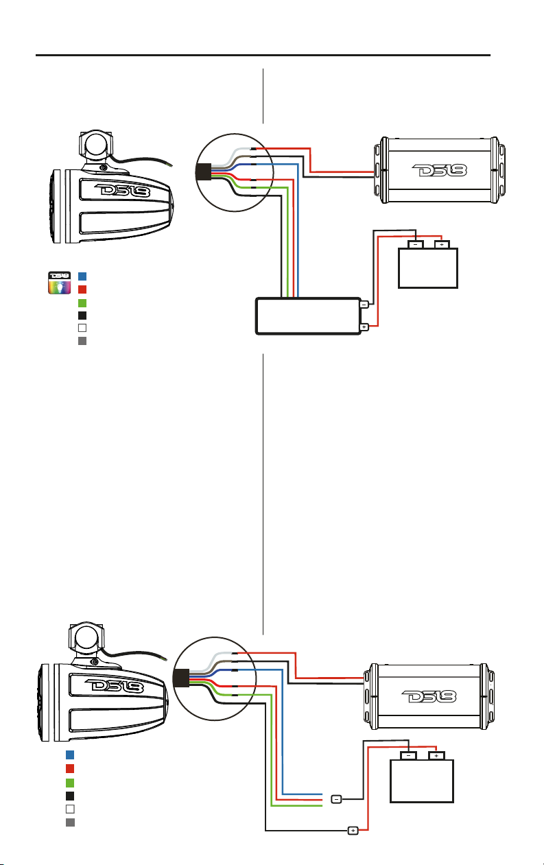
9. Decide early what type of LED lighting you
want (if any) and wire accordingly
(NOTE :if you want "Dancing Light" look to the
WiFi or RF or BT remote controlled LED light
box. The easy way to have lighting ... YOUR
way!)
1. Asegúrese de leer detenidamente y entender
las instrucciones antes de intentar instalar
estos altavoces.
2.Porseguridad,desconecteelterminalnegativodela
batería de la batería antes de empezarla instalación.
3. Para facilitar el montaje, le sugerimos que
tenga todas sus herramientas a mano: taladro,
juego de llaves Allen, engarzadores, soldador,
pelacables,tubo termo retráctil, etc.
4. Utilice conectores "a prueba de agua" de alta
calidad para una instalación confiable y para
minimizar la pérdida de señal o energía.
5. ¡Piense antes de taladrar! Tenga cuidado de
no cortar ni perforar tanques de gasolina, líneas
de combustible, líneas de frenos o hidráulicas,
líneas de vacío o cableado eléctrico cuando
trabaje en cualquier vehículo. Si se instala en un
barco. Tenga cuidado de no cortar ni perforar el
casco principal.
6. Nunca coloque cables cerca de líneas de
combustible o de energía (si es posible). Pasar
los cables dentro del área del casco proporciona
la mejor protección.
7. Evite pasar cables sobre o a través de bordes
afilados. Utilice ojales de goma o plástico para
proteger los cables que atraviesan el metal,
especialmente la torre.
8. Asegúrese de que las abrazaderas de montaje
estén apretadas antes de abandonar la base.
9. Decida con anticipación qué tipo de
iluminación LED que desea usar (si aplica) y
conéctelo según corresponda.
(NOTA: si desea "Luces Dinámicas", utilice un
módulo controlador de luz LED (LED-BTC). La
manera másfácil de tener iluminación a tu manera!)
INSTALLATION EQUIPMENT
• An Electric Drill With Bits
• Allen / Hex Key / Wrench Set
• Philips Head And Standard Screw Drivers
• Wire Strippers
• Crimping Tool
• Vom (Electronic Volt Ohm Meter)
• Heat Shrink Tubing And Heat Gun
• Soldering Iron
• Electronic (Rosen Not Acid Core) solder
• Un taladro eléctrico con bocas
• Allen / Llave hexagonal / Juego de llaves
• Destornilladores estándar Phillips
• Pelacables
• Herramienta de presión
• Vom (voltímetro electrónico)
• Tubo termorretráctil y pistola de calor
• Soldador
• Soldadura electrónica (núcleo de ácido rosen)
EQUIPO DE INSTALACIÓN
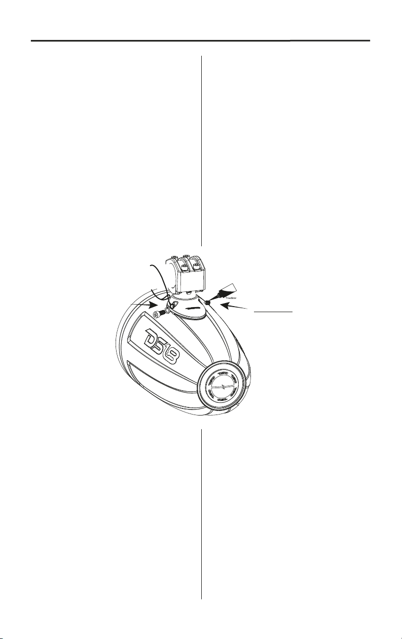
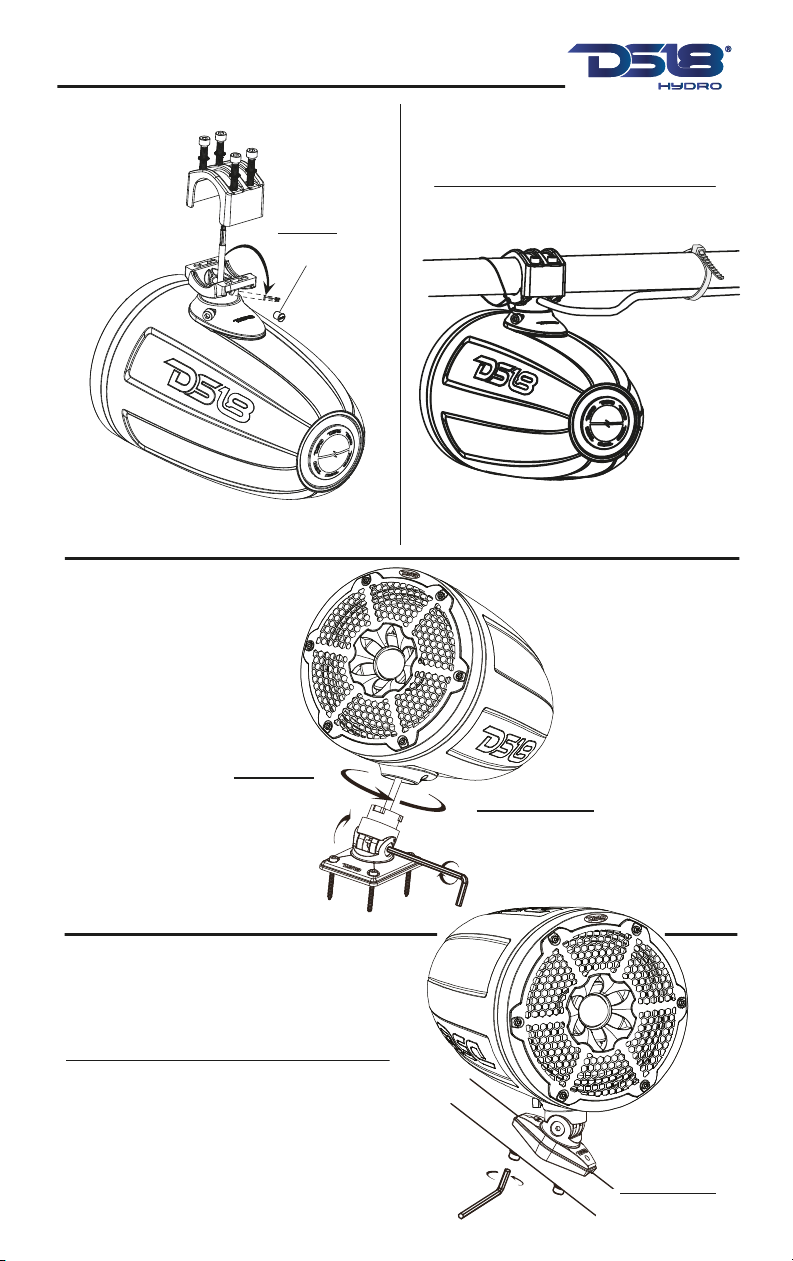
INSTALLATION / INSTALACIÓN
READ BEFORE INSTALLATION LEER ANTES DE LA INSTALACIÓN
1. Be sure to carefully read and understand the
instructions before attempting to install these
speakers.
2. For safety, disconnect the negative battery
terminal from the battery prior to beginning the
installation.
3. For easier assembly, we suggest you have all
your tools in hand- Drill, Allen set, Crimp, Soldering
iron, Wire Strippers, Heat-shrink, etc.
4. Use high quality "Waterproof' connectors for
a reliable installation and to minimize signal or
power loss.
5. Think before you drill! Be careful not to cut or
drill into gas tank, fuel lines, brake or hydraulic
lines, vacuum lines or electrical wiring when
working on any vehicle. If installing in a boat,
make sure not cut or drill through the main hull.
6. Never run wires near fuel lines or power (if
possible). Running the wires inside the hull or
car area provides the best protection.
7. Avoid running wires over or through sharp
edges. Use rubber or plastic grommets to
protect any wires routed through metal,
especially the tower.
8. Make sure that the mounting clamp or "L"
bracket are tight before leaving the dock.
9. Decide early what type of LED lighting you
want (if any) and wire accordingly
(NOTE :if you want "Dancing Light" look to the
WiFi or RF or BT remote controlled LED light
box. The easy way to have lighting ... YOUR
way!)
1. Asegúrese de leer detenidamente y entender
las instrucciones antes de intentar instalar
estos altavoces.
2.Porseguridad,desconecteelterminalnegativodela
batería de la batería antes de empezar la instalación.
3. Para facilitar el montaje, le sugerimos que
tenga todas sus herramientas a mano: taladro,
juego de llaves Allen, engarzadores, soldador,
pelacables,tubo termo retráctil, etc.
4. Utilice conectores "a prueba de agua" de alta
calidad para una instalación confiable y para
minimizar la pérdida de señal o energía.
5. ¡Piense antes de taladrar! Tenga cuidado de
no cortar ni perforar tanques de gasolina, líneas
de combustible, líneas de frenos o hidráulicas,
líneas de vacío o cableado eléctrico cuando
trabaje en cualquier vehículo. Si se instala en un
barco. Tenga cuidado de no cortar ni perforar el
casco principal.
6. Nunca coloque cables cerca de líneas de
combustible o de energía (si es posible). Pasar
los cables dentro del área del casco proporciona
la mejor protección.
7. Evite pasar cables sobre o a través de bordes
afilados. Utilice ojales de goma o plástico para
proteger los cables que atraviesan el metal,
especialmente la torre.
8. Asegúrese de que las abrazaderas de montaje
estén apretadas antes de abandonar la base.
9. Decida con anticipación qué tipo de
iluminación LED que desea usar (si aplica) y
conéctelo según corresponda.
(NOTA: si desea "Luces Dinámicas", utilice un
módulo controlador de luz LED (LED-BTC). La
manera másfácil de tener iluminación a tu manera!)
INSTALLATION EQUIPMENT
• An Electric Drill With Bits
• Allen / Hex Key / Wrench Set
• Philips Head And Standard Screw Drivers
• Wire Strippers
• Crimping Tool
• Vom (Electronic Volt Ohm Meter)
• Heat Shrink Tubing And Heat Gun
• Soldering Iron
• Electronic (Rosen Not Acid Core) solder
• Un taladro eléctrico con bocas
• Allen / Llave hexagonal / Juego de llaves
• Destornilladores estándar Phillips
• Pelacables
• Herramienta de presión
• Vom (voltímetro electrónico)
• Tubo termorretráctil y pistola de calor
• Soldador
• Soldadura electrónica (núcleo de ácido rosen)
EQUIPO DE INSTALACIÓN
INSTALLATION / INSTALACIÓN