©2000 Digital Security Controls Ltd.
Toronto, Canada • 1-800-387-3630 • www.dsc.com
Printed in Canada 29005212 R001
4. Enrolling the Module
Once all wiring is complete, the module must be enrolled
on the system. To enroll the module:
1. Enter installer’s programming by pressing [*] [8]
[Installer’s Code].
2. Scroll to “Module Hardware” and press the [*] key.
3. Scroll to “Enroll Module” and press the [*] key.
4. Scroll through the different modules until “PC4702
Fire” is displayed. Press the [*] key.
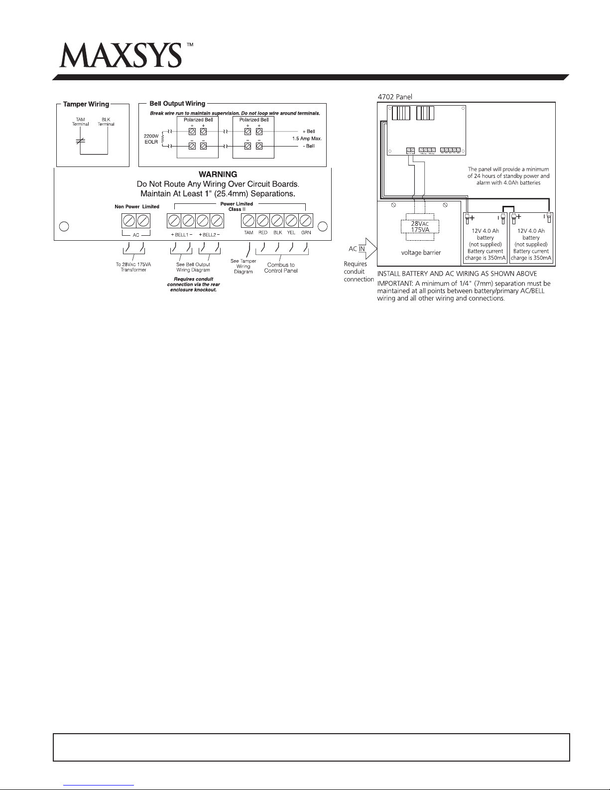
5. The keypad will prompt, “Create tamper on desired
unit.” After you create and restore the tamper (see
Tamper Wiring on front), the keypad will confirm
enrollment (e.g. “PC4702 Fire Mode XX Enrolled”).
For more information regarding module enrollment, see
the control panel Installation Manual.
Output Partition
Option 1 2 3 4 5 6 7 8
PC4702 module no.: 01
[0007070101] Bell Output 1 I
______I______II
______I______I______I______I______I______I______I______I
[0007070102] Bell Output 2 I
______I______II
______I______I______I______I______I______I______I______I
Location: __________________________________________________________
PC4702 module no.: 02
[0007070201] Bell Output 1 I
______I______II
______I______I______I______I______I______I______I______I
[0007070202] Bell Output 2 I
______I______II
______I______I______I______I______I______I______I______I
Location: __________________________________________________________
PC4702 module no.: 03
[0007070301] Bell Output 1 I
______I______II
______I______I______I______I______I______I______I______I
[0007070202] Bell Output 2 I
______I______II
______I______I______I______I______I______I______I______I
Location: __________________________________________________________
PC4702 module no.: 04
[0007070401] Bell Output 1 I
______I______II
______I______I______I______I______I______I______I______I
[0007070202] Bell Output 2 I
______I______II
______I______I______I______I______I______I______I______I
Location: __________________________________________________________
This unit may contain a time limit cut-out on the bell circuit.
Programmed cut-out time is ___________.
5. Programming the Module
To access PC4010/PC4020 programming, enter [*][8]
followed by the Installer’s code.
Enter the reference numbers indicated below to jump to
the PC4702BP programming sections. Enter one of the
recommended output options and which partition(s) the
output will be active on for each output. Record your
programming choices in the space below.
You may also need to program the following sections:
Ref #: [000200] Fire Timeout (Y)
Ref #: [00020300] Bell Cut-off (005)
Ref #: [00020309] Fire Silence Del (000)
Refer to your control panel Installation Manual for more
information on these programming sections. Record
your programming choices for these sections in your
control panel’s Programming Worksheets book.
Recommended Output
Options:
[49] Steady Fire
[50] Temporal Fire
[51] CSFM Fire
[52] Pulsed Fire
[53] Fire Strobe
Record your PC4702BP programming choices here:
Bell Loop Wiring Chart
To ensure proper operation, the wire length of the bell
loop must be considered.
Consult the following chart to determine the maximum
wire length for the bell loop with respect to current.
Bell Loop
Load
Current
Distance to last bell/siren (ft/m)
18 AWG
Wire
16 AWG
Wire
14 AWG
Wire
1.8A 51/16 81/25 129/39
1.0A 92/28 147/44 233/70
0.7A 132/40 210/64 332/101
0.5A 184/56 293/89 465/141
0.1A 922/279 1467/445 2326/705