DSYS DL16B User manual

1
2020 rev. 02
Version HW: 1.1 / SW: 6.1
USER GUIDE
MODEL ELECTRONICS
PERFORMANCE AND QUALITY
DL16B (W)
RC LED LIGHTING
Operation
Acoustic Signalling
Wiring
Settings
Operating Instructions
Technical Specifications
Package content
Information, Support, Service
RC LED Lighting Controller DL16B
RC Switches / ESCs - DS4C
Programmer DPG4
DC ESCs CLEVER
RC Opto-isolator DOP1C
RC LED Lighting Controller DL4B
RC Switches DS1C
ORDER

Car / Boat / Plane / BUS
Plug the ESC cable in to lower K1 connector, plug the lower cable to the
ESC receiver channel. Plug the servo cable in to upper K1 connector,
connect the cable to receiver servo channel. The cables can be
connected also to spare receiver channels.
DL16B is designed for LED lighting of RC 3-channel control of
models.
WIRING
W - resistant to splashing water, snow, humidity and dust.
TIR, Tractor, Tank, Dinghy, Sub, Glider.
2
Lower cable /L1 L4÷
connecting cable CH3 /OFF, L8
Upper cable /L5 L7÷
L1
+L Power supply LED
(connected anodes)
L2
L3
L4
L5
L6
L7
L8
+L
L1
L2
L3
L4
L5
L6
L7
L8
1
2
3
4
5
6
S
W
5V G
GND
CH1
CH2
K1
CH3
SET
Reflectors
2x 5x LED÷
Footlights
Rear / Front
Left blinkers
Right blinkers
Rear / Front
Brake / Rear
left / right
Beacon
left / right
Reverse
Front - -
left / right
A
A
A
A
A
A
A
A
B
B
B
B
B
B
B
B
ESC
OFF
Servo
RC receiver
CH2 CH3CH1
DL16B
N: J601
Universal RC
LED Lighting DL16B DL16BW
RC Models

3
+A -C +A
-C
Connect all LED anodes to positive (+) battery pole.
Example 1. 8x NiMH (8 x 1,2 = 9,6V), 3 LED 2,1V in series.
Calculation: 9,6-0,6-(3 x 2,1) = 2,7. 3 LEDs can be used.
When the voltage drops under 5V the LEDs light intensity decrease.
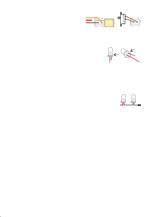
Solder the wires to connector’s counterparts. Cut the LEDs lead to 5mm
length, extend the leads with wires and isolate them properly.
The types and colours of used LEDs can be
combined.
Example 2. 3S Li-Pol (3 x 3,7) = 11,1V), 4 LEDs 2,1V.
The maximum number of connected LEDs is determined by the
battery voltage per formula: Uaku -0,6-(n x Uled). Uaku= battery
voltage, 0,6V=stabilization, n=number of LEDs, Uled=LED voltage.
The calculated value must be between 0 - 5 (otherwise its overloaded).
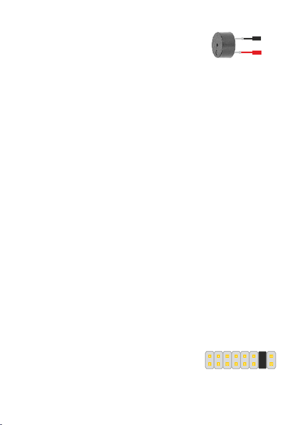
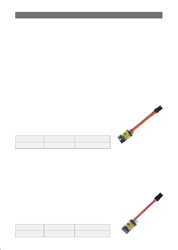
Connect the S1 switch or the cable
plugged into the free channel of the
receiver to the CH3 connector.
powerful LEDs !) You can connect any of L1-L8 A, B outputs.
If you use standalone battery to power the LEDs then connect its
negative pole to the K1 connector G pin.
You can connect one 3V LED (white, blue) or two red
2,1V LEDs. By connecting the K2 outputs (e.g. L1A with
L1B) the current is increased to 40mA (Only for
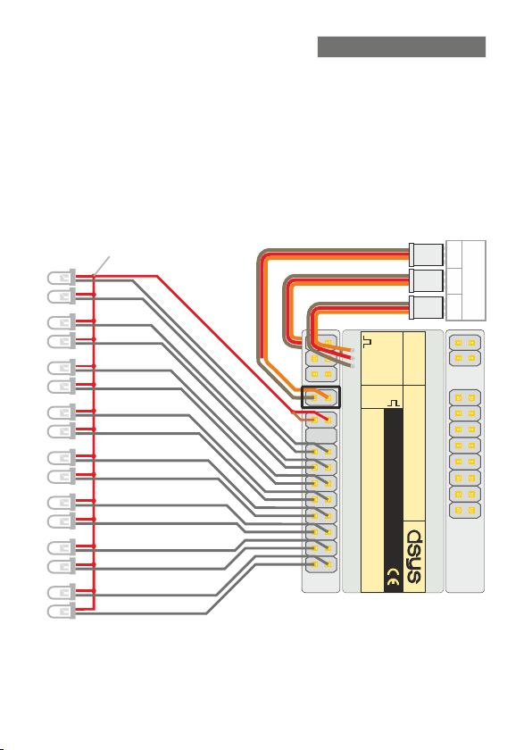
Powering LEDs from the Receiver (+5V). Connect the LEDs
cathodes to L1-L8 (A, B) connector pins. Connect the common
LED’s anodes to +L (A, B). The + L (A, B) terminals are internally
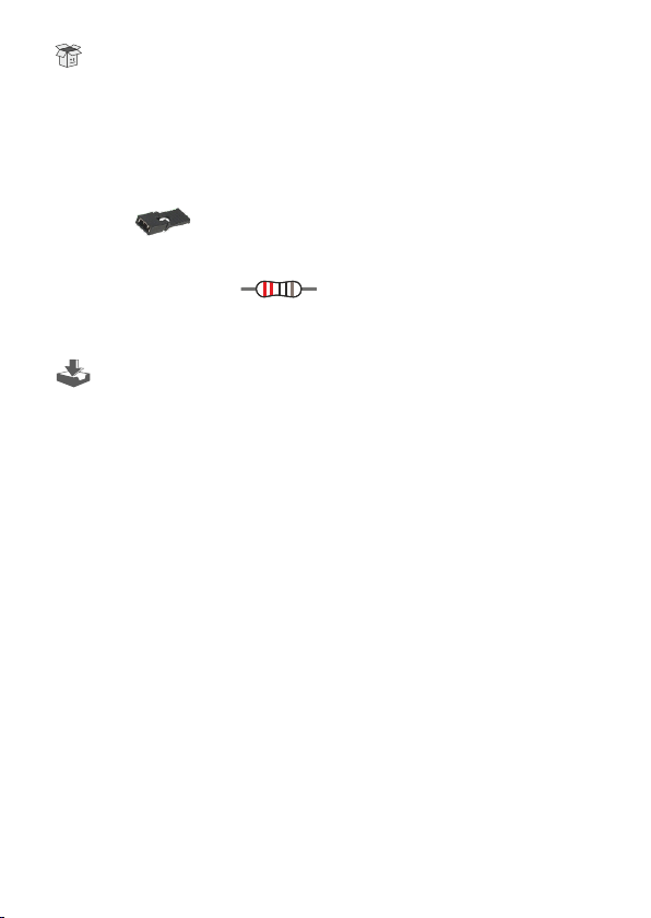
connected. Do not connect any resistors to LEDs. The outputs
provide 20mA current.
Calculation. 11,1 - 0,6 - (4 x 2,1) = 2,1. 4 LEDs can be used on one
output.
LED polarity: flat side (usually shorter
lead) is negative (Cathode).
LED Powering from Driver Battery (connection see page 4 - footlights).
Switch S1
CH3
Cable CH3

4
o
R1
220R L7
B A
E1 E2 E3 E4 E5
L7
B
A
E1 E2 E3 E4
Battery
drive
Battery
drive
GND
GND
-
-
+
+
Examples of LED wiring.
L4: L8: Position Reflector
L3: / L7: FootlightsInner Beacon
LED POWERING FROM DRIVER BATTERY (used for L1÷L8)
CAR
L1: Front, Sidelights L5: (Front / Rear)Right blinkers
L2: Reverse L6: (Front / Rear)Left blinkers
L4: Brake / L8: Rear Reflector
BOAT
L1: L5: mFront Reflectors Auxiliary ast
L2: L6: CabinRear Reflectors
L4: L8: Position Reflector
AIRPLANE
L2: L6: Beacon Flash lights
L3: Taxiing L7: Footlights
L3: L7: FootlightsBeacon
L1: L5: Anti-collision, 1Landing Auxiliary
FOOTLIGHTS Connect cathodes LED E2, E4 to 4x LED, white, 5mm.
terminals L7 A, B. Connect anodes LED E1, E3 to the positive (+)
terminal of the battery. Cut the LEDs lead to 5mm length, extend the
leads with wires and isolate them properly.
FOOTLIGHTS Connect the terminals A, B of 5x LED, white, 5mm.
the L7 connector and connect the E2, E4 LED cathodes and the R1
resistor terminal L7 A, B. Anodes E1, E3, E5 to + battery.

5
OPERATION
Control: Stick / Wheel / Switch Position 2P / 3P Switch.
LED L8 is permanently ON when the switch is switched ON.
ACOUSTIC SIGNALLING
Connect the KPX1 piezo buzzer instead of the
LED L2B. Set the blinking L2 while reversing
and the siren will beep intermittently.
After turning the model on the LEDs will blink and then respond to
control respectively.
Switching ON by LED switch S1: set switch S1 to the OFF (the LEDs
are switched ON by OFF the switch).
Switching ON the LED with 3P switch (on the transmitter) and LED L8
control. In the down position, all LEDs are OFF. In the middle
position, L1 to L7 are ON (depending ON the setting), L8 is OFF.
Switching from middle to upper position turns ON L8 (reflector).
Hazard blinkers LED L5 and L6: first moving wheel from straight to
left and back you turn ON blinking LEDs, second turn ON 2x flashing
LEDs, third turn OFF LEDs, other turn ON blinking LEDs etc.
LED L7: first moving wheel from straight to right and Footlights
back you turn ON LED L7, second turn ON blinking L7, third turn OFF
L7, other turn ON L7 etc.
Switched on L5, L6, L7 can only be switched OFF when the stick is in
neutral.
L1-L7 flashes when no cables are connected or a signal failure (> 0.5s).
Only selected LEDs indicate the LED operation during setup. Test your
changes during setup.
- Insert the jumper into one connector position
1 to 6, S, W to select LEDs L1 to L6 or S
(stick), W (wheel).
- Use the jumpers in the SET connector to set
the desired properties of the selected LED, S,
W.
SETTINGS (without programming)
- To finish the setting, remove the jumper from connector 1 to 6, S, W
and then remove the jumpers from the SET connector.
Move the stick to neutral and wheel straight for 1s.
Control of hazard blinkers and by steering wheel.footlights
+L
L2B
+
Select LED L2
W S 6 5 4 3 2 1

6
1: Operation LED L1A, L1B (lower cable control).
S: Selection of the shift of the neutral position of the neutral lever or
the stop position ON LEDs L1 to L4 (according to the setting).
W: Steering wheel middle shift selection, LEDs L5, L6 ON.
1: 0 2: +25 3: +50 4: +100 5: -25 6: -50 7: -100
1: 0 2: +25 3: +50 4: +100 5: -25 6: -50 7: -100
1
SET 2345 6 7
3 Reversible - - blinking - blinking
Mode Activity Bwd N / Stop Fwd Brake MBrake
1 Reversible lights 25% lights 25% lights lights 25% lights
2 Reversible - - lights - lights
4 Unidirect. - - lights - lights
6 Unidirect. - - flash - flash1x 1x
7 Unidirect. flash flash- - 2x - 2x
5 Unidirect. - lights blinking - blinking
2: Operation LED L2A, L2B (lower cable control).
3: Operation LED L3A, L3B (lower cable control).
5 Unidirect. - blinking flash - flash2x 2x
3 Unidirect. - - lights - lights
4 Unidirect. - blinking flash - flash1x 1x
Mode Activity Bwd N / Stop Fwd Brake MBrake
2 Reversible blinking - - - -
1 Reversible lights - - - -
6 blinking constantly
7 2 flash constantlyx
5 Unidirect. - - flash - flash2x 2x
Mode Activity Bwd N / Stop Fwd Brake MBrake
3 Reversible flash - flash flash flash2x 2x 2x 2x
2 Reversible blinking - blinking blinking blinking
7 1 flash constantlyx
4 Unidirect. - - blinking - blinking
6 lights constantly
1 Reversible lights - lights lights lights

7
Standard: Bwd 1000 / Neutral 1500 / Fwd 2000µs
„-” no function, no light.
* Reversible: bidirectional, forward and reverse. Neutral, it is in the
middle position of the lever (car, boat).
* Unidirectional: unidirectional, forward only. Stop is fully backward
(airplane, dinghy).
* Brake M: sharp reduction in power (in the forward direction).
* S/W: Offset position shift in microseconds.
4: Operation LED L4A, L4B (lower cable control).
5: Operation LED L5A, L5B (upper cable control).
6: Operation LED L6A, L6B (upper cable control).
6 Unidirect. - lights - - -
1 Reversible lights 25% lights 25% lights 25% lights lights
Mode Activity Bwd N / Stop Fwd Brake MBrake
2 Reversible - - - lights lights
4 Reversible - lights - - -
7 blinking constantly
3 Reversible lights lights lights- -
5 Unidirect. - lights - lights-
5 blinking constantly
1 - - blinking
3 - - 1 flashx
6 1 flash constantlyx
2 - - lights
7 2 flash constantlyx
Mode Left Straight Right
4 lights constantly
Mode Left Straight Right
2 lights - -
4 lights constantly
1 blinking - -
3 2 flash - -x
7 2 flash constantlyx
6 1 flash constantlyx
5 blinking constantly

8
Stand by Current Consumption: c. 0,01A
Output Current L1- L8: c.20mA
TECHNICAL SPECIFICATIONS
Input Voltage MDL16: +5 V from connector K1 (4V ÷ 8V)
External Battery Voltage: +4 to +24V.
Operate current consumption: 0,03 ÷ 0,35A (depends on load)
Signal Protection masks signal los: 0,5s.
Control (positive pulses): T = 5÷30ms, t = 1,5ms ± 0,7ms
Dimension L x W x H: 29 x 42 x 8 mm
Weight / (W): 12g / 14g
Ambient Temperature: -10°C ÷ +40°C
The board is coated with varnish to protect it against humidity, dust.
OPERATING INSTRUCTIONS AND SAFETY RULES
Intended environment: housing, business and light industry
Read user guide thoroughly and follow its instructions!
Do not exceed maximum voltage rating.
Do not charge battery while connected to DL16B.
Protect your DL16B against drops, aggressive environment, liquids,
splashing water and snow (line “W” is resistible against splashing
water and snow). Do not connect DL16B to battery when taking it from
cool to hot environment, wait at least for 20 minutes.
If you discover any defect on the DL16B, please return the product to
your seller with the defect description.
When the product is no longer in use, return it to a collection point for
recycling.
Do not look directly into LED light from small distance. Protect your
eyes.
Prevent short-circuit of any wires by proper insulation.
Check the wiring before every use.
Wrong wiring could cause the DL16B damage even its ignition.
!

9
Visit our website/ e-shop at ................... www.dsys.cz
QUALITY: All our products are undergoing series of tests to ensure high
reliability, long lifetime and consistent safety.
RC Model Electronic - Manufacturing / Service.
Piezo buzzer KPX1 ............................................ 1 pc
(2x white 3,2V / 4x orange 2,2V)
Connecting cable CH3, 2 wire cable 2m ................ 2 pc
ENVIRONMENT: When the product is no longer in use, return it to a
collection point for recycling.
Contact us on email.
Business related ........................................ sales@dsys.cz
Switch S1 ............................................................. 1 pc
INFORMATION, TECHNICAL SUPPORT, SERVICE
Zdenek David, Hrusnova 12, Brno 62100, Czech Republic
Resistor 220R / 0,25W ....................... 1 pc
Super LED 3mm, 20mA ........................................ 6 pc
Heat Shrink tube 82mm / 0mm .............................. 3 pc
You can download all users’ guides at (support).www.dsys.cz
Information and Support ............................ [email protected]
SERVICE: We provides expert advice, warranty/expired warranty
repair services. If you discover any defect on the product,
please return the product to your seller with the defect
description.
Connector J2, J20 ................................................ 2 pc
Jumper ............................................... 3 pc
WARRANTY: Our product are guaranteed for 24 months. The warranty
covers all manufacturing and components defects. The
warranty does not apply to damage caused by: wear and
tear, mechanical damage, improper usage, Accident,
Unauthorized service and unauthorized modifications.
PACKAGE CONTENT
Super LED 5mm, 20mA ........................................ 13 pc
DL16 (W) with user guide ...................................... 1 pc
(9x white 3,2V / 2x red 2,1V / 2x blue 3,2V)

10
PŘEHLED PRODUKTŮ
Car, TIR, tank: front and rear, inner, reflector.
DL4B - Universal RC LED Lighting Controller
Setting with 1 jumpers. Very simple operation and adjustment.
Content: 8x super LED 5 mm, Jumper F1-6, connector, cable.
1 channels control (Stick, Wheel, Switch).
Boat: Mast, front, cabin, rear
Aeroplane. reflector, landing, beacon, position
4 outputs for 1 - 32 LED 20mA.
W - resistant to splashing water, dust
Type S1-S4 Current Case size
DS1C (W) 3A (5A / 3s) 25 x 14 x 4 mm
Type L1-4 Current Case size
DL4B (W) 40mA 25 x 14 x 4 mm
Switching: horn, beacon, ramp, LED strips, bulbs, motor, relay,
smoke, reel.
Electronic accessory switch in models and models of cars, tractor, tank,
ship, submarine, aircraft, mechanical machine.
Battery: 2- 4S Li-Pol, 5 - 12 Ni-MH, Pb 6V / 12V.
W - resistant to splashing water, dust
DS1C - 1x Switches
Control: Stick, Wheel, Switch. .Very simple operation
ORDER
(for the same or different products)
Our products are available at RC Model Shops / e-shop
Standard Shipping: 2 - 5 working days.
We provide shipping by Czech Post, debiting payment method only.
Shop online at e-shop: www.dsys.cz
Quantity discount: 2pcs -5%, 5pcs -7%, 10pcs -10%
PRODUCT OVERVIEW

11
2 user quick settings by jumper or switch (M1, M2 memories).
Battery: DDE20A, 70A: 5 - 10 Ni-Cd / Ni-MH, 2 - 3S Li-Pol /
DDE6A: 3 - 6 Ni-Cd / MH, 1 - 2S Li-Pol / Li-ion, Pb 6V.
Car, Boat, Plane, BUS, TIR, Tractor, Tank, Dinghy, Sub, Glider.
Universal DC ESC Brushed - Reversible / Unidirectional
2 LEDs status indication (red and green LEDs).
Li-ion / A123 Li-Fe, Pb 6V / 12V.
Powerful BEC: D DE20A, 70A: 3A / 4,5A with overload protection.
DDE6A: 5V - 1A / 1,5A with overload protection.
Extremely smooth motor speed control and acceleration. BUS control.
W - resistant to splashing water, snow, humidity and dust
DDE6A (W) 6A (8A 3s) 24 x 20 x 8mm
Type Current Case size
DDE20A (W) 20A (25A 3s) 34 x 25 x 10mm
DDE70A (W) 70A (85A 3s) 47 x 33 x 11mm
DOP1C (W) 23 x 12 x 6 mm
Type Case size
Reduces servos twitching
DOP1C - Universal RC Electronic Opto-isolator
RC Receiver from ESC/Servos Galvanic Opto-isolation
Read / Write of setting values.
Portable, no other device needed.
Number of Parameters 1 - 99
Fast and Easy Programming.
Size 36 x 31 x 8mm
Number of Values 1 - 9
DPG4 - Electronic Programmer

12
DL16B - 3CH Universal RC LED Lighting Controller
2 - 3 channels control (Stick, Wheel, Switch).
Setting with 3 jumpers. Very simple operation and adjustment.
Content: 13x super LED 5 mm, 6x super LED 3 mm, 3x jumper, Piezo
Buzzer, connectors, cables, switch, heat shrink tubes.
CAR, track, tank: Right/Left Blinkers, headlights, rear and reversing
lights roof lights and beacons, hazard warning lights, lights bar.
Airplane: position lights, anti-collision lights, landing and taxi lights.
16 controllable outputs for 1 - 96 LEDs (20mA).
Warning lights and ramp controlled by wheel.
Boat: position lights, navigation lights, cabin and auxiliary lights.
Reflector controlled by 3rd channel CH3.
W - resistant to splashing water, dust
Type LED Current Case size
DL16B (W) 20mA 26 x 45 x 6 mm
Type S1-S4 Current Case size
DS4C (W) 3A (5A / 3s) 26 x 36 x 5 mm
2 channels control (Stick, Wheel, Switch).
Setting with 1 jumper. Very simple operation and adjustment.
Selection of 1 function from 9 preset: 1 type for 2 ESCs for smooth
motor speed control, 3 types for 1 ESC and 2 Switches, 5 types for
4 Switches.
Power: 2- 3S Li-Pol, 5 - 10 Ni-MH/Cd, Pb 6V / 12V.
DS4C - RC 4x Switches / 2x ESCs
Switching: horn, beacon, ramp, LED strips, bulbs, motor, relay,
smoke, reel.
W - resistant to splashing water, dust
We reserve the right to make changes without notice to the user
This manual suits for next models
1