Radionode UA10 User manual

©2014 DEKIST Co., Ltd. Rev. 1.2
UA10 / UA11
RADIONODE
Real Time USB Temp/RH Transmitter
Temp / RH
T Type Thermocouple 2CH
K Type Thermocouple 2CH
32CH Data Logging SW (Tapaculo Lite)
High Accuracy Humidity Sensor
5V USB Power Source
Product Overview
UA10/UA11 is designed to measure
temperature and humidity and send these data
to PC in real time. All the required sensors are
included in the box or in product itself. In case
of T or K type product, It has two channel input
port for thermocouple sensor. One is included
in the box..
In Operating Software (MS Windows) will
detect UA10, UA11 device as a COM port.
The given bundle software, Tapaculo Lite
support 16 devices connected to USB or
network. This means up to 32 CH data can
be monitored in Tapaculo Lite.
Application Block Diagram
•USB Data Logger
•Contact/Contactless Temp Sensor
•Relative Humidity Sensor
Where to Use
•Food Storage
•Bio Technology Lab.
•HVAC
•Pharmacy Ware House
•LCD/Semiconductor Fab.
Order Number
•MODEL :UA10-CHS
•MODEL :UA11-CTS
Terminal for UA11 device

©2014 DEKIST Co., Ltd. Rev. 1.2
1.Specification
UA10 / UA11Specification
Dimension
H70 * W25 * D13 (mm)
Measurement
Range
UA10
Temp: -40℃~ 80℃
Humidity: 5% ~ 95%RH
Power
5V(USB Power), 50mW
UA11
K Type : 0℃~ 1000℃
T Type : -100℃~ 300℃
Sample Interval
1 Second
Accuracy
UA10
Temp: ±0.3℃
Humidity:±2.0%RH
USB Port
USB 2.0 Type A Plug
UA11
K Type :±0.8℃
T Type : ±0.8℃
Temp. Scale
℃/℉
Resolution
UA10
Temp: 0.01℃
Humidity: 0.04%RH
Operating
Range
Temp : -40~80°C
Humidity : 5~ 95%RH
UA11
K Type : 0.05℃
T Type : 0.07℃
2.Contents
Model
Contents in a box
UA10-CHS
UA10 Device (1EA) , USB Extension Cable(1EA) , Software (1EA)
UA11-CTS
UA11 Device (1EA) , T Type Thermocouple Sensor(1EA) ,Software CD(1EA)
3.How to Connect
PC Connection
Thermocouple Connection
<UA10 PC Connection>
UA10 has Temp/RH sensor inside of the device.
User can connect it to PC via USB extension cable.
<UA11 PC Connection>
UA11 need to attach thermo couple sensor and
then user can connect them to PC directly. USB
extension cable is not included for UA11.
There are two terminals in a thermo couple
sensor. Normally red line is PLUS [+].
Please be careful of direction.
★A channel that has no TC sensor will have
abnormal value close to room temperature.
Software Installation
User need to install the tapaculo lite software
in the given CD.USB driver is also in the CD.

©2014 DEKIST Co., Ltd. Rev. 1.2
4. Operating
4.1 Data Logging In Local PC
UA10, UA11 device can be connected to Local PC via USB port directly. The Tapaculo software supported
up to 16 devices. If you have several device and shortage of USB ports, you can add normal USB hub
device. All the data will be stored in Local PC hard disk via Tapaculo lite.
4.2 Data Logging In Remote PC
UA10,UA11 devices can send data to remote PC using RN171(Ethernet),RN171(WIFI). RN171, RN172
transmitter can be purchased separately. For more information of Ethernet or WIFI, please refer to the
RN171 manual or web site.
5.USB Console Commands
UA10-CHS, UA11-CTS are recognized as a COM serial port in MS windows. For advanced usage or other
application, user can directly access UA10, UA11 devices. Below table have some commands that similar
to AT commands.
Command
Description
Respond
ATCZ\n
Check Physical Connection
ATCZ OK\r\n
ATCD\n
Request Current Data Value.
ATCD 1.0,-20.1\r\n
ATCD 49.3,10.4\r\n
ATCD -21.1,-22.0\r\n
ATCMODEL\n
Request Product Serial Number
ATCMODEL 12345678\r\n
ATCVER\n
Request Product Version.
ATCVER UA10_1v0\r\n
ATCVER UA11_1v1\r\n
ATCOFF1 0.49\n
Set Offset for Channel 1
ATCOFF1 0.49\r\n

©2014 DEKIST Co., Ltd. Rev. 1.2
ATCOFF2 -0.55\n
Set Offset for Channel 2
ATCOFF2 -0.55\r\n
ATCOFF1\n
Show Current Offset for Channel1
ATCOFF1 0.49\r\n
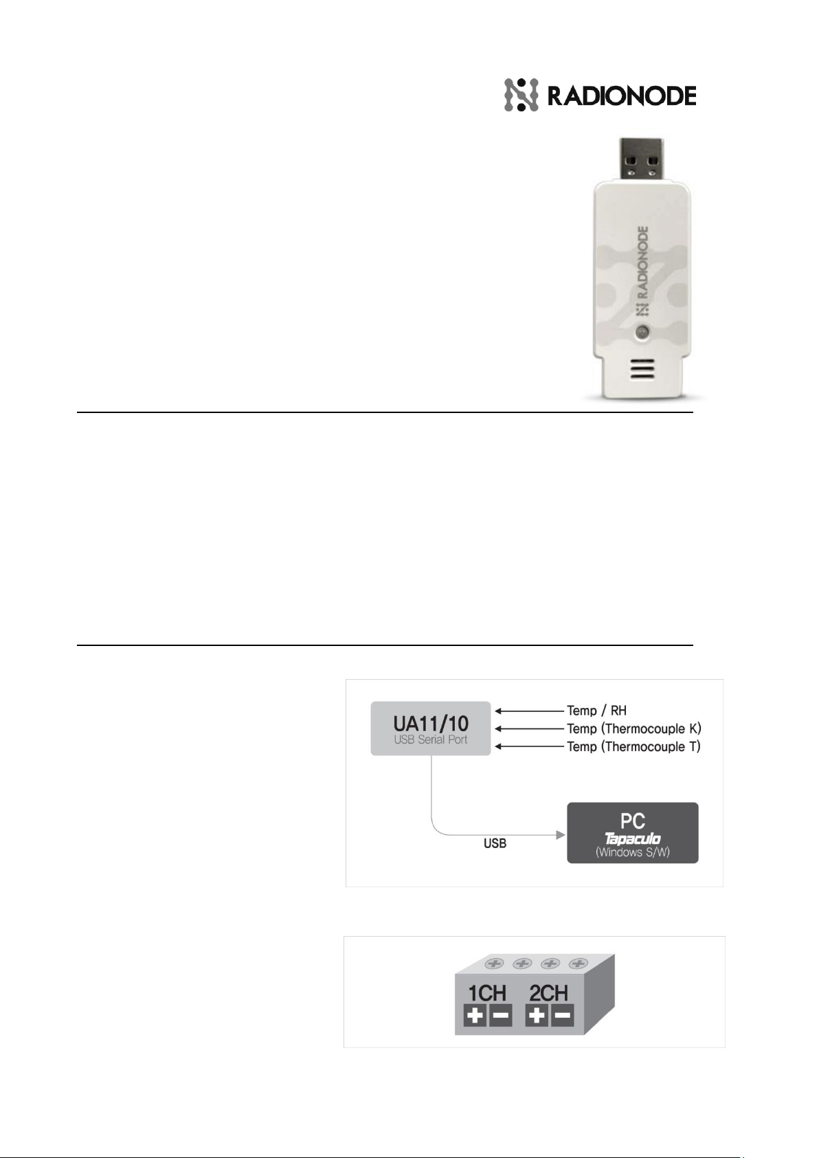
*USB Serial COM Port (19200 BPS, 8BIT, 1Stop, N)
6. LED Indicator
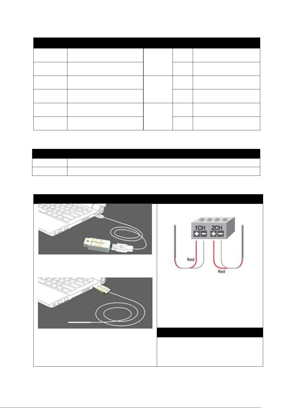
Once UA device connect to PC, Red LED turns on. Red LED will turn off right after initializing process.
This is normal waiting status. If the Red LED is not turning off, user needs to re-connect the device. Every
time the devices are sensing data, Green LED would be blink.
In case of UA10, there is a timer for humidity sensor life time. The timer keep monitor the time usage
of humidity sensor. The life time of two year is recommended for high accuracy measurement. When the
timer exceeds two years, Red LED will keep blinking continuously. This situation is just for warning signal.
User can use UA11, UA10 devices as usual.
LED
Description
Etc.
RED LED KEEPS ON
Connection is not normal. Try to re-connect..
GRRED LED BLINK
Device Read Sensor and Send it to the host
RED LED KEEPS BLINK
UA10 humidity sensor may need to be changed.
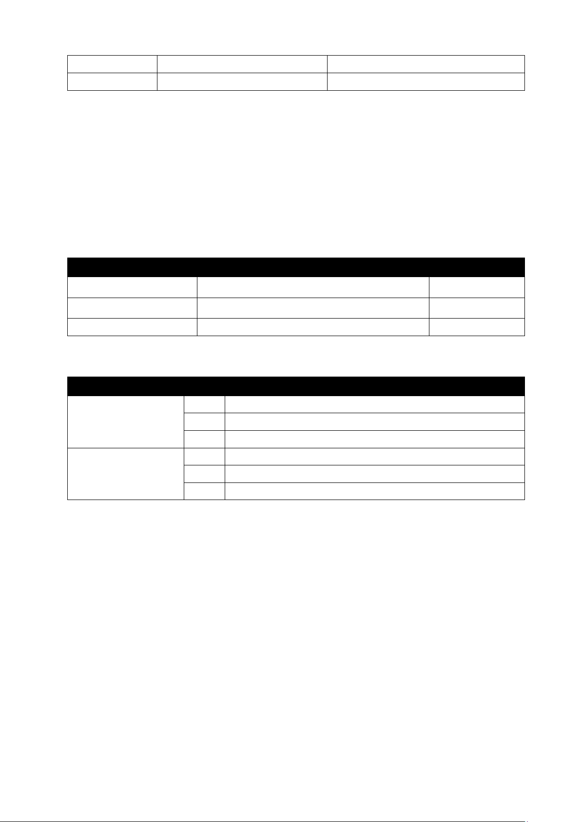
UA10 Only
7. Model Number
Model Number
Description
UA10-X1X2X3
X1
C = Celsius(℃), F= Fahrenheit(℉)
X2
H=Temp/RH , T= Temperature Only
X3
S= Serial Communication, H=HID Communication
UA11-X1X2X3
X1
C = Celsius(℃), F= Fahrenheit(℉)
X2
K=K Type Thermocouple , T=T Type Thermocouple
X3
S= Serial Communication, H=HID Communication
ex>UA10-CHS : UA10 Celsius(℃), CH1=Temp, CH2=RH, Serial Comm.
UA11-CTS : UA11 Celsius(℃), 2CH T type T/C, Serial Comm.

©2014 DEKIST Co., Ltd. Rev. 1.2
8. PC Monitoring Software (Tapaculo® Lite)
All the measured data from UA20 (4-20mA), UA11 (T/C), UA30 (PT100), UA10 (Temp/RH) device can be recorded
into PC application, Tapaculo® Lite.
Tapaculo Lite Bundle SW can handle up to 32 data stream and support real time trending chart, daily report tool
and historical viewer functions. For more detailed information, please see Tapaculo Lite Manual.
-Real Time Dash Board (Color/Buzzer Alarm) -
-Real Time Trending Chart -

©2014 DEKIST Co., Ltd. Rev. 1.2
9. Certification
▷FCC Class A digital device
NOTE: This equipment has been tested and found to comply with the limits for a Class A digital device, pursuant to part 15 of the FCC Rules.
These limits are designed to pro-vide reasonable protection against harmful interference when the equipment is operated in a commercial
environment..This equipment generates, uses, and can radiate radio frequency energy and, if not installed and used in ac cordance with the
instruction manual, may cause harmful interference to radio communications. Operation of this equipment in a residential area is likely to
cause harmful interference in which case the user will be required to correct the interference at his own expense. CAUTION: Changes or
modifications not expressly approved by the manufacturer responsible for compliance could void the user ’s authority to operate the
equipment.
10. Question & Service
Free repair service within one year
Damage caused by user’s negligence or
device’s overexposure to extreme
environment is go to paid repair.
Company : DEKIST Co., Ltd
Phone : +82 (0)70-7529-4359
Fax : +82 (0)31-8039-4400
Email : [email protected]
Web Page : www.radionode365.com
This manual suits for next models
1
Table of contents
Other Radionode Transmitter manuals
Popular Transmitter manuals by other brands

AZECA
AZECA BTT005 owner's manual

Endress+Hauser
Endress+Hauser FHX50 installation guide

Hama
Hama 00014164 operating instructions

Camel RF Electronic
Camel RF Electronic transmitter instruction manual

Vaisala
Vaisala HUMICAP HMT310 user guide

Williams Sound
Williams Sound WIR TX90 Installation guide & user manual