DTE CoolMaster K1 Series User manual

Title: CoolMaster K1 Series
Document: Operating manual
Company: Dutch Thermal Engineering n.v.
Revision no.: D
Language: EN

T h e N e t h e r l a n d s
w w w . d t e . e u
Dutch Thermal Engineering n.v.
Westerbroekstraat 18
7011 EX Gaanderen
Phone : +31(0)315-328311
Specialist in:
Industrial ….Cooling
….Heating
….Tempering
….Heat Recovery
Revision no.: D Operating manual - CoolMaster K1 Series Page 2
INDEX
1DISCLAIMER ................................................................................................................................................................... 3
2DECLARATION OF CONFORMITY* .................................................................................................................................. 4
3SAFETY INSTRUCTIONS AND WARNINGS........................................................................................................................ 6
3.1 WATER DRAINING,PACKING,TRANSPORT AND STORAGE INSTRUCTIONS OF DTE INSTALLATIONS......................................................... 7
3.1.1 Draining water from the machine.......................................................................................................................... 7
3.1.2 Packing, transport and storage instructions .......................................................................................................... 7
3.2 CORRECT APPLICATIONS ....................................................................................................................................................... 8
3.3 APPLICATION AREA.............................................................................................................................................................. 8
4GENERAL DESCRIPTION.................................................................................................................................................. 9
4.1 IDENTIFICATION................................................................................................................................................................ 11
5COMMISSIONING......................................................................................................................................................... 12
5.1 CONNECTING COOLING WATER PIPES .................................................................................................................................... 13
5.2 CONNECTING OVERFLOW PIPE ............................................................................................................................................. 14
5.3 CONNECTING POWER SUPPLY .............................................................................................................................................. 14
5.4 CONNECTING EXTERNAL CONTACTS....................................................................................................................................... 14
5.5 WATER QUALITY ............................................................................................................................................................... 15
5.6 FILLING OF (EXTERNAL)PIPES AND SYSTEMS COOLMASTER (K)................................................................................................... 16
5.7 FILLING OF THE SYSTEM COOLMASTER (K) ............................................................................................................................. 16
5.8 DEAERATING.................................................................................................................................................................... 17
5.9 SETTING THERMOSTAT ....................................................................................................................................................... 18
5.10 COMMISSIONING AFTER LONG STANDSTILL............................................................................................................................. 19
6FAULT ANALYSIS .......................................................................................................................................................... 20
7MINIMUM INSPECTION-INTERVAL SCHEME................................................................................................................. 21
8CLEANING OF THE MACHINE ........................................................................................................................................ 22
9CHECKS ........................................................................................................................................................................ 23
10 SERVICE.................................................................................................................................................................... 24
11 GUARANTEE ............................................................................................................................................................. 24
12 REMOVAL................................................................................................................................................................. 24
13 APPENDIX................................................................................................................................................................. 25
13.1 CONNECTION DIAGRAM FILLING THE SYSTEM .......................................................................................................................... 26
13.2 WATER TREATMENT .......................................................................................................................................................... 27
13.3 GUIDELINE FOR WATER QUALITY IN DTE INSTALLATIONS........................................................................................................... 28
13.4 USER MANUAL THERMOSTAT (IF APPLICABLE)* ....................................................................................................................... 29
13.5 SAFETY INFORMATION SHEETS ............................................................................................................................................. 30
13.6 COMMENTS..................................................................................................................................................................... 38
13.7 TECHNICAL INFORMATION* ................................................................................................................................................ 39
➢
Machine drawing ......................................................................................................................................................... 39
➢
P&ID............................................................................................................................................................................. 39
➢
Parts list ....................................................................................................................................................................... 39
➢
Electrical diagram ........................................................................................................................................................ 39
➢
User manual thermostat.............................................................................................................................................. 39
➢
Safety data sheet refrigerant....................................................................................................................................... 39
➢
Other............................................................................................................................................................................ 39
OPERATING MANUAL
EN

T h e N e t h e r l a n d s
w w w . d t e . e u
Dutch Thermal Engineering n.v.
Westerbroekstraat 18
7011 EX Gaanderen
Phone : +31(0)315-328311
Specialist in:
Industrial ….Cooling
….Heating
….Tempering
….Heat Recovery
Revision no.: D Operating manual - CoolMaster K1 Series Page 3
1 Disclaimer
The manufacturer reserves the right to change parts at any time to change, without prior or immediate notice to the customer. The contents of
this manual may also be changed without prior warning. This is an original manual, and is valid for the machine in its standard version. The
manufacturer can therefore not be held liable for any damages resulting from specifications that deviate from the standard version delivered to
you. For information on adjustments, maintenance and repair insofar as this guide does not provide it, please contact the technical department
of your supplier. This manual was drawn up with the greatest possible care, however the manufacturer cannot accept any liability for any errors
in this book or any consequences thereof. Finally, this manual is a personal and confidential communication to the user. No part of this
publication may be reproduced, copied, altered or transmitted in any form or in any manner whatsoever without written permission from Dutch
Thermal Engineering n.v.

T h e N e t h e r l a n d s
w w w . d t e . e u
Dutch Thermal Engineering n.v.
Westerbroekstraat 18
7011 EX Gaanderen
Phone : +31(0)315-328311
Specialist in:
Industrial ….Cooling
….Heating
….Tempering
….Heat Recovery
Revision no.: D Operating manual - CoolMaster K1 Series Page 4
2 Declaration of conformity*
EU declaration:
Manufacturer: D.T.E. n.v.
Address: Westerbroekstraat 18
7011 EX GAANDEREN / HOLLAND
Hereby certifies that:
The CoolMaster meets the requirements of the Machinery Directive
(Directive 2006/42/EC, as amended),
and the national legislation implementing this Directive;
Meets the provisions of the following other EC directives.
- 2014/35/EU Low voltage directive
- 2014/30/EU EMC-directive
- 2014/68/EU Pressure Equipment Directive (PED)
And certify that:
The following (parts of) harmonized standards are applied:
- NEN-EN-IEC 60204-1:2018
- NEN-EN-ISO 12100:2010
- NEN-EN 378-2:2016
- NEN-EN-ISO 13857:2019
The following (parts of) national technical standards and specifications are used:
- Regulation EU 517/2014.
Made in Gaanderen on 12-12-2018
………………………….
F.G.R. Geerdink
General Manager
*This is an example, the original declaration will delivered with the machine!

T h e N e t h e r l a n d s
w w w . d t e . e u
Dutch Thermal Engineering n.v.
Westerbroekstraat 18
7011 EX Gaanderen
Phone : +31(0)315-328311
Specialist in:
Industrial ….Cooling
….Heating
….Tempering
….Heat Recovery
Revision no.: D Operating manual - CoolMaster K1 Series Page 5
UKCA declaration:
Manufacturer: D.T.E. n.v.
Address: Westerbroekstraat 18
7011 EX GAANDEREN / HOLLAND
Hereby certifies that:
The CoolMaster meets the requirements of the Machinery Directive
(Directive Supply of Machinery (Safety) Regulations 2008, as amended),
and the national legislation implementing this Directive;
Meets the provisions of the following other UKCA directives:
- Electrical Equipment (Safety) Regulations 2016
- Electromagnetic Compatibility Regulations 2016
- Pressure Equipment (Safety) Regulations 2016
And certify that:
The following (parts of) harmonized standards are applied:
- NEN-EN-IEC 60204-1:2018
- NEN-EN-ISO 12100:2010
- NEN-EN 378-2:2016
- NEN-EN-ISO 13857:2019
The following (parts of) national technical standards and specifications are used:
- Regulation EU 517/2014.
Made in Gaanderen on 12-12-2018
………………………….
F.G.R. Geerdink
General Manager
*This is an example, the original declaration will delivered with the machine!

T h e N e t h e r l a n d s
w w w . d t e . e u
Dutch Thermal Engineering n.v.
Westerbroekstraat 18
7011 EX Gaanderen
Phone : +31(0)315-328311
Specialist in:
Industrial ….Cooling
….Heating
….Tempering
….Heat Recovery
Revision no.: D Operating manual - CoolMaster K1 Series Page 6
3 Safety instructions and warnings
Always observe the following safety instructions and warnings!
WARNING!
Warning of possible damage to the device, environment or user
WARNING!
Warning of electricity and / or current threat
WARNING!
Warning of possible entrapment hazard
Compliance with the technical manual is a prerequisite for fault-free operation and the honouring of any
warranty claims. Therefore please read the technical manual carefully before you start working with
your device! The manual must therefore be kept near the machine. The CoolMaster is under pressure
with a refrigerant, more information about this can be found in Appendix 13.5.
This user’s manual was written for types similar to DTE CoolMaster (K) type machines. Therefore
certain topics may not apply to your machine. For the same reason, the images may differ slightly from
how your machine actually looks. The machine drawing is sent separately as an attachment with the
correct dimensions and connections.

T h e N e t h e r l a n d s
w w w . d t e . e u
Dutch Thermal Engineering n.v.
Westerbroekstraat 18
7011 EX Gaanderen
Phone : +31(0)315-328311
Specialist in:
Industrial ….Cooling
….Heating
….Tempering
….Heat Recovery
Revision no.: D Operating manual - CoolMaster K1 Series Page 7
3.1 Water draining, packing, transport and storage instructions of DTE installations.
These actions are general and have to been carried out, of course, if applicable for the
application by qualified personal!
3.1.1 Draining water from the machine
Step 1: Switch off the CoolMaster via the connection (F) with an ON-OFF switch on the rear.
Step 2: Close the filling connection (D1).
Step 3: Drain the water tank of the cooling system by opening the drainage valve.
Step 4: Dry clean all connections and water tank with a wet vacuum cleaner.
3.1.2 Packing, transport and storage instructions
Before packing, transport and storage, first follow the instructions of chapter 3.1.1 Draining
water from the machine.
Attention! Before transport the machine has to be protected with the delivered cardboard box or
has to be wrapped with bubble wrap. The machine has to be transported and stored vertically at
all times on its fundament on the provided pallet!
The machine has to be placed vertically on its fundament at all times.
Attention! In no way the machine can be stacked or overturned. This applies during transport
and storing as well during repairs and commissioning. Even when the machine is not used it
should be vertically at all times.
Attention! Not following these instruction can cause severe damage to the machine.
Always use the correct type of transportation equipment, such as a pallet truck and a forklift
truck.

T h e N e t h e r l a n d s
w w w . d t e . e u
Dutch Thermal Engineering n.v.
Westerbroekstraat 18
7011 EX Gaanderen
Phone : +31(0)315-328311
Specialist in:
Industrial ….Cooling
….Heating
….Tempering
….Heat Recovery
Revision no.: D Operating manual - CoolMaster K1 Series Page 8
3.2 Correct applications
The CoolMaster (K) may only be kept inside a cool, well-ventilated, frost-free building!
The minimum and maximum ambient temperature can be found in the relevant P&ID.
The CoolMaster (K) is only suitable for tap water of drinking quality.
Please consult the relevant P&ID for information on the minimum and maximum environmental
temperature.
Attention! In no way the machine can be stacked or overturned. This during transport and
storing as well during repairs and commissioning. Even when the machine is not used it should
be perpendicular at all times.
Attention! Not following these instruction can cause big damage to the machine.
3.3 Application area
CAUTION! Application is prohibited:
- In explosive atmospheres.
- In environments with hazardous oils, acids, gases, fumes, substances, radiation, etc.
- Corrosive environment.

T h e N e t h e r l a n d s
w w w . d t e . e u
Dutch Thermal Engineering n.v.
Westerbroekstraat 18
7011 EX Gaanderen
Phone : +31(0)315-328311
Specialist in:
Industrial ….Cooling
….Heating
….Tempering
….Heat Recovery
Revision no.: D Operating manual - CoolMaster K1 Series Page 9
4 General description
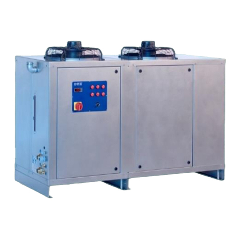
The CoolMaster is a complete plug and play water cooler with integrated water cooler tank, pump, condenser
and controls. Is built for perfect cooling in closed industrial process water systems.
CoolMaster sample drawing*:
*The machine drawing is sent separately as an attachment with the correct dimensions and connections!

T h e N e t h e r l a n d s
w w w . d t e . e u
Dutch Thermal Engineering n.v.
Westerbroekstraat 18
7011 EX Gaanderen
Phone : +31(0)315-328311
Specialist in:
Industrial ….Cooling
….Heating
….Tempering
….Heat Recovery
Revision no.: D Operating manual - CoolMaster K1 Series Page 10
A
=
Cooling water inlet, see P&ID
B
=
Cooling water outlet, see P&ID
C+E
=
Drainage/overflow water tank, see P&ID
D1
=
Filling water connection, see P&ID
D2
=
Manual filling device, see P&ID
F
=
Bushing coupling electrical supply cable
G
=
Control panel
H
=
Incoming condenser air
I
=
Removable cover
NOTE: POSITION THE COVER (I) BEFORE SWITCHING ON THE MACHINE!
J
=
Fixing bolts cover
K
=
Air grille outgoing condenser air
L
=
Rubber legs
P
=
Sight glass
Maximum water level
Minimum water level

T h e N e t h e r l a n d s
w w w . d t e . e u
Dutch Thermal Engineering n.v.
Westerbroekstraat 18
7011 EX Gaanderen
Phone : +31(0)315-328311
Specialist in:
Industrial ….Cooling
….Heating
….Tempering
….Heat Recovery
Revision no.: D Operating manual - CoolMaster K1 Series Page 11
4.1 Identification
The identification plate is located on the left above the fan. (Figure 4.1)
A
=
Machine number/ serial number
Figure 4.1
B
=
Machine type
C
=
Voltage
D
=
Maximum Current
E
=
Number of phases
F
=
Frequency in Hz.
G
=
Refrigerant type
H
=
Refrigerant mass
I
=
Maximum ambient temperature
J
=
CO2 equivalent
K
=
GWP-values
L
=
Thermostat Temperature range
M
=
Maximum pressure
N
=
Compressor lubrication
O
=
Compressor oil volume
P
=
Built
Q
=
Weight
R
=
Cooling capacity

T h e N e t h e r l a n d s
w w w . d t e . e u
Dutch Thermal Engineering n.v.
Westerbroekstraat 18
7011 EX Gaanderen
Phone : +31(0)315-328311
Specialist in:
Industrial ….Cooling
….Heating
….Tempering
….Heat Recovery
Revision no.: D Operating manual - CoolMaster K1 Series Page 12
5 Commissioning
See for the connections chapter 4.
CAUTION! The installation work must be carried out by a certified professional!
Place the CoolMaster at a level position and at least 1 meter from a wall. For a good functioning of the
CoolMaster we recommend keeping the distance between the CoolMaster and the user to a
minimum. The cooling water pipes between the CoolMaster and the user must be longer than 20
meters.
WARNING! The diameter of the pipes/hoses must at least match with the connections on the
CoolMaster.
The hoses must be reinforced with braided fibre to prevent kinking the hose.

T h e N e t h e r l a n d s
w w w . d t e . e u
Dutch Thermal Engineering n.v.
Westerbroekstraat 18
7011 EX Gaanderen
Phone : +31(0)315-328311
Specialist in:
Industrial ….Cooling
….Heating
….Tempering
….Heat Recovery
Revision no.: D Operating manual - CoolMaster K1 Series Page 13
5.1 Connecting cooling water pipes1
Let op! Before making any connections to the CoolMaster, clean the external pipes. Dirt must be
prevented from entering the CoolMaster. It may cause serious damage to the system and the
CoolMaster.
Connect the following pipes:
- Cooling water pipes (A) and (B) between CoolMaster and the user.
- D1: If you wish to fill automatically.
Step 1:
1. Install the ball valve (BVS-1) on the cooling water inlet (A). See appendix §13.1
2. Install cooling water pipe between CoolMaster and user. See appendix §13.1
The ball valve must be kept closed, unless otherwise indicated!
Step 2:
1. Install the ball valve (BVS-2) on the cooling water outlet (B). See appendix §13.1
2. Install the ball valve (BVS-3) on the T-piece (central section). See appendix §13.1
3. Install the cooling water pipe between CoolMaster (on the T-piece) and the user. See appendix
§13.1
The ball valves (BVS-2 and (BVS-3) must be kept closed, unless otherwise indicated!
Step 3:
1. Connect the cooling water pipes between CoolMaster and user to ball valves on the cooling water
inlet (A) and T-piece (central section), See appendix §13.1
2. Connect (D1) to a water tap if you wish to fill automatically.
1Ball valves are not supplied as standard

T h e N e t h e r l a n d s
w w w . d t e . e u
Dutch Thermal Engineering n.v.
Westerbroekstraat 18
7011 EX Gaanderen
Phone : +31(0)315-328311
Specialist in:
Industrial ….Cooling
….Heating
….Tempering
….Heat Recovery
Revision no.: D Operating manual - CoolMaster K1 Series Page 14
5.2 Connecting overflow pipe
Connect the overflow pipe (C+E). To enable good outflow of superfluous water, the overflow pipe must
be able to flow out into the open sewer without any foreseeable obstructions. The length of the overflow
pipe should be kept to a minimum. The pipe should also flow downwards, from the perspective of the
CoolMaster (C+E).
5.3 Connecting power supply
Switch off the CoolMaster via the connection (F) with an ON-OFF switch on the rear.
Connect your electrical power supply cable to the appropriate terminals in the control box via the cable
entry (F).
Consult the type plate for the correct voltage.
Attention! Ensure the voltage as stated on the type plate is also the voltage on each phase wire.
Of no less importance is the mains frequency (50 or 60 Hz) corresponding to the frequency on the type
plate. The maximum voltage deviation is +6% and –10% from the voltage indicated on the type plate.
5.4 Connecting external contacts
Also connect the electrical cables for the external contact(s).
See for supplied electrical diagram.

T h e N e t h e r l a n d s
w w w . d t e . e u
Dutch Thermal Engineering n.v.
Westerbroekstraat 18
7011 EX Gaanderen
Phone : +31(0)315-328311
Specialist in:
Industrial ….Cooling
….Heating
….Tempering
….Heat Recovery
Revision no.: D Operating manual - CoolMaster K1 Series Page 15
5.5 Water quality
CAUTION! The CoolMaster is not suitable for use with demineralized water or water containing
high levels of minerals or iron.
The filling water which is used must be of good quality. It must at least be of drinking water quality and
the water must not contain high levels of lime and/or iron, as it may cause serious damage.
You must check the water regularly.
The minimum filling pressure must be 2,5 bar.
See Appendix §13.2 for extra information.
See Appendix §13.3 for directive water quality.

T h e N e t h e r l a n d s
w w w . d t e . e u
Dutch Thermal Engineering n.v.
Westerbroekstraat 18
7011 EX Gaanderen
Phone : +31(0)315-328311
Specialist in:
Industrial ….Cooling
….Heating
….Tempering
….Heat Recovery
Revision no.: D Operating manual - CoolMaster K1 Series Page 16
5.6 Filling of (external) pipes and systems CoolMaster (K)
Step 1:
1. All the connections must be made in accordance with §5.1
2. Turn the air vent(s) in your system to “open”. (The venting
must take place at the highest point(s) in pipe(s))
CAUTION! Do not use automatic air vents!
3. Connecting the filling water (min. 2.5 Bar) to ball valve (BVS-3).
4. Turn the ball valve (BVS-3) to “open”.
Step 2:
Excess air will be released from the pipe(s) though the air release valve(s).
If the water spills from the air release valve(s), the external pipes/systems are filled with water.
1. Turn the ball valve (BVS-3) on the T-piece (central section) to “closed”.
2. Turn the air release valve(s) in your system to the "closed" position.
3. Turn the water fill line to “closed”.
4. Remove the fill water line which is mounted on the (BVS-3).
Step 3:
1. Turn the ball valve (BVS-1) on the cooling water inlet (A) to “open”.
2. Turn the ball valve (BVS-2) on the cooling water outlet (B) to “open”.
When these steps have been completed correctly, the entire system will be filled with water.
5.7 Filling of the system CoolMaster (K)
Fill the CoolMaster with water (fill automatically or manually):
1. Auto fill (D1) (a power supply is required; a minimum filling
pressure of 2.5 bar is required).
2. Manual fill (D2).
External systems must be filled via an external filling point.
See chapter §5.6 for instructions.
WARNING! To add any chemicals or other substances, please consult the supplier.

T h e N e t h e r l a n d s
w w w . d t e . e u
Dutch Thermal Engineering n.v.
Westerbroekstraat 18
7011 EX Gaanderen
Phone : +31(0)315-328311
Specialist in:
Industrial ….Cooling
….Heating
….Tempering
….Heat Recovery
Revision no.: D Operating manual - CoolMaster K1 Series Page 17
5.8 Deaerating
WARNING! DO NOT START THE PUMP BEFORE IT IS FILLED WITH LIQUID AND DEAERATED!
This machine is fitted with a bypass and will therefore automatically be deaerated.
WARNING! Ensure the compressor is disabled when starting up for the first time!
By starting the pump the system automatically be deaerated.

T h e N e t h e r l a n d s
w w w . d t e . e u
Dutch Thermal Engineering n.v.
Westerbroekstraat 18
7011 EX Gaanderen
Phone : +31(0)315-328311
Specialist in:
Industrial ….Cooling
….Heating
….Tempering
….Heat Recovery
Revision no.: D Operating manual - CoolMaster K1 Series Page 18
5.9 Setting thermostat
See chapter §4 for the specified parts.
CAUTION! COVER(I) MUST BE PLACED, BEFORE STARTING
UP THE MACHINE!
Switch on the CoolMaster via the connection (F) with an ON-OFF switch on the rear.
Set the thermostat to the correct value, which is on the front of the control panel (G).
See appendix §13.4 for the settings.
CAUTION! It is important that the values in the P&ID are adhered to, otherwise damage to the
compressor may occur! When temperatures set incorrectly the guarantee claim may expire!
WARNING! This machine is equipped with a bypass, which is erected between water supply and
water return pipe inside the CoolMaster. The minimum flow is already factory defined and may
not be hanged!
The CoolMaster is now ready for use.

T h e N e t h e r l a n d s
w w w . d t e . e u
Dutch Thermal Engineering n.v.
Westerbroekstraat 18
7011 EX Gaanderen
Phone : +31(0)315-328311
Specialist in:
Industrial ….Cooling
….Heating
….Tempering
….Heat Recovery
Revision no.: D Operating manual - CoolMaster K1 Series Page 19
5.10 Commissioning after long standstill
CAUTION! BEFORE OPENING MACHINE, ALWAYS
ENSURE POWER SUPPLY IS COMPLETELY
DISCONNECTED!
Figure 5.1
DTE uses renowned components in her products, which will
reduce the chance of failure of a machine.
This also applies to the water pump. These pumps are made
with a stainless steel fan, a high quality pump house and a
“Mechanical seal” to seal the axis.
The mechanical seal is a seal from polished hard metal. This
will guarantee a good sealing in even the hardest
circumstances. The mechanical seal will lubricate itself by a
small liquid layer supplied from the pumped fluid.
When the machine has not been used for a long period it
could be possible that the water pump will not run. The cause
of this problem is cohesion between the both polished seals.
The seals will stick together. This problem can be solved
easily by rotating the pump axis by hand. It depends of the
pump type how this can be done.
The rotation of the pump axis can be done there a
screwdriver on the axis of the pump. At the backside of the
pump is a hole. (See Figure 5.1). When a screwdriver is put
on the axis and is turned a bit, the seals will be loosened and
the pump will run by a machine start.

T h e N e t h e r l a n d s
w w w . d t e . e u
Dutch Thermal Engineering n.v.
Westerbroekstraat 18
7011 EX Gaanderen
Phone : +31(0)315-328311
Specialist in:
Industrial ….Cooling
….Heating
….Tempering
….Heat Recovery
Revision no.: D Operating manual - CoolMaster K1 Series Page 20
6 Fault analysis
Have all checks and repairs performed by a certified technician!
Fault →
Possible cause →
Check and solution
1. Unit does not start
1.1. Faulty wiring
1.2. Components down to earth
1.3. Faulty main switch
1.4. Controls incorrectly set
1.1. Check wiring and connections
1.2. Check and replace
1.3. Check and replace
1.4. Check, see electric diagram
1.5. Place removable cover
2. Fan(s) run but
compressor will not
start
2.1. Faulty wiring
2.2. Faulty security
2.3. Faulty compressor
2.1. Check wiring and connections
2.2. Check components
2.3. Check and replace
3. Compressor starts but
no air is delivered over
the condenser
3.1. Fan loose on shaft
3.2. Faulty fan motor
3.3. Faulty wiring
3.4. Blocked air flow
3.1. Tighten fixing screw
3.2. Check and replace
3.3. Check wiring and connections
3.4. Clean the condenser
4. Compressor switches
off
4.1. Electricity supply
4.2. Faulty thermostat
4.3. Faulty security
4.4. Internal security activated
4.1. Check electricity supply
4.2. Check and replace
4.3. Check and replace
4.4. Water and/or ambient temperature
too high. Check cleanliness of
condenser and clean it
5. Unit does not cool
5.1. Shortage of refrigerant
5.2. Faulty compressor
5.3. Faulty thermostat
5.4. Faulty pump
5.1. Refill refrigerant
5.2. Check and replace
5.3. Check and replace
6. Water pump gives
no water
6.1. Water pump not de-aerated
6.2. Impeller of water pump is stuck
6.3. Faulty security
6.1. De-aerate water pump
6.2. See: chapter 5.10
6.3. Check components
7. Shortage of refrigerant
7.1. Leak in the refrigerant system
7.1. Check the refrigerant system for
leakage and repair
Table of contents
Other DTE Water Dispenser manuals
Popular Water Dispenser manuals by other brands

Halsey Taylor
Halsey Taylor HVR8BL*1D owner's manual

Frigidaire
Frigidaire EFWC505 use & care

Excalibur
Excalibur SUPERIOR SOFT-TEC Installation & operation manual

AquA NanO
AquA NanO LIFEFILTA Operation

Kogan
Kogan KAINHWDSPNA quick start guide

TAVLIT
TAVLIT ADIR Series Installation and maintenance instructions