DTS Megashock 5 User manual

1
Base plate-mounting instructions
E-EEEE
DTS Megashock 5
Energizer 5J (Indoor installation)
INSTALLATION MANUAL
Comply to: SANS IEC 60 335-2-76
NRCS Ref. no. 7357 10 14
DTS SECURITY
P.O.BOX 3399
EDENVALE
1610
TELEPHONE 086 1000 387
Spartan +2711 392 5540 (H/O)
Pretoria +2712 361 5528
Alberton +2711 907 8846
Natal +2731 916 3266
www.dtssecurity.co.za

2
Introduction
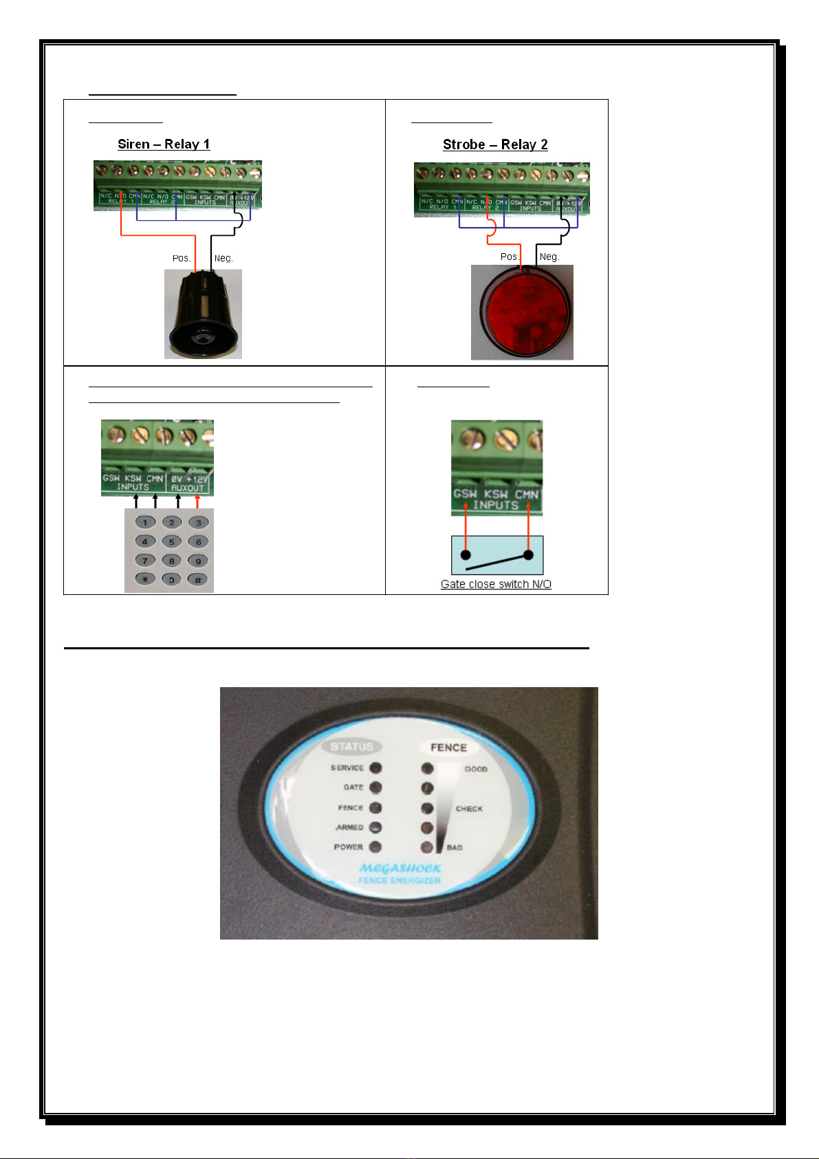
The Megashock 5 is a mains (230V 50Hz nominal) operated energizer with battery (12V 7Ah nominal) back-up.
The batteries to be used are rechargeable lead-acid batteries. Non rechargeable batteries must NOT be used. The lead-acid
batteries require venting and it is imperative that the energizer be situated in a well-ventilated area.
This appliance is not intended for use by persons (Including children) with reduced physical, sensory or mental
capabilities, or lack of experience and knowledge, unless they have been given supervision or instruction concerning the
use of the appliance by a person responsible for their safety.
Children should be supervised to ensure that they do not play with the appliance.
Disclaimer
DTS Security Products CC or any of its subsidiary companies does not guarantee that the operation of the product will be
uninterrupted or totally error free. Energizer specifications may be altered without prior notification. The installer is
referred to the definitions and general requirements in Appendix A.
The installer must take into consideration the applicable municipal laws concerning the installation of electric fences.
International standards can be viewed at http://www.iec.ch and South African standards on http://www.sabs.co.za.
Basic Definitions
Electric Fence: a barrier which includes one or more electric conductors, insulated from earth, to which electric pulses are
applied by an energizer.
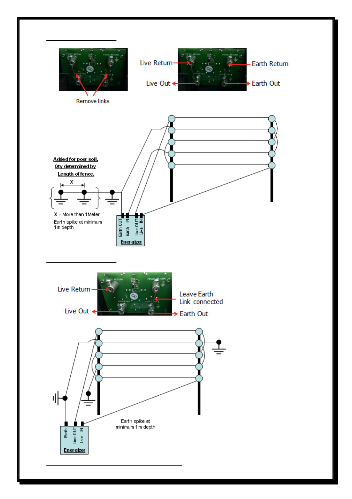
Connecting Lead: an electric conductor, used to connect the energizer to the electric fence or the earth electrode.
Electric Security Fence: a fence used for security purposes which comprises an electric fence and a physical barrier
electrically isolated from the electric fence.
Public Access Area: any area where persons are protected from inadvertent contact with pulsed conductors by a physical
barrier.
Pulsed Conductors: conductors which are subjected to high voltage pulses by the energizer.
Secure Area: an area where a person is not separated from pulse conductors below 1,5m by a physical barrier.
General requirements for electric security fences (Appendix A)
Electric fences shall be installed and operated so that they cause no electrical hazard to persons, animals or their
surroundings.
Electric fence constructions which are likely to lead to the entanglement of animals or persons shall be avoided.
An electric fence shall not be supplied from two different energizers or from independent fence circuits of the same
energizer.
For any two different electric fences, each supplied from a different energizer independently timed, the distance between
the wires of the two electric fences shall be at least 2 meters. If this gap is to be closed, this shall be done by means of
electrically non-conductive material or an isolated metal barrier.
Barbed wire or razor wire shall not be electrified by an energizer.
Any part of an electric fence which is installed along a public road or pathway shall be identified at frequent intervals by
prominently placed warning signs securely fastened to the fence posts or firmly clamped to the fence wires. The size of
the warning signs shall be at least 100mm x 200mm. The background colour of both sides of the warning sign shall be
yellow. The inscription on the sign shall be black. The inscription shall be indelible, inscribed on both sides of the
warning sign and have a height of at least 25 mm.
Warning signs shall be placed at each gate, access point, intervals not exceeding 10 meters, adjacent to each sign relating
to chemical hazards for the information of emergency services.
Gates in electric security fences shall be capable of being opened without the person receiving an electric shock.
The energizer earth electrode shall penetrate the ground to a depth of at least 1,2 meter. The distance between any electric
security fence earth electrode and other earth systems shall not be less than 2 meters.
Connecting leads that run inside buildings shall be effectively insulated from the earthed structural
parts of the building. This may be achieved by using insulated high voltage cable.
Connecting leads that are run underground shall be run in a conduit of insulating material or else insulated high voltage
cable shall be used. Care shall be taken to avoid damage to the connecting leads due to external factors.
Connecting leads shall not be installed in the same conduit as the mains supply wiring, communication cables or data
cables.
Connecting leads and electric fence wires shall not cross above overhead power or communication lines.
Mains supply wiring shall not be installed in the same conduit as signaling leads associated with the electric security
fence installation.
Crossings with overhead power lines shall be avoided wherever possible. If such a crossing cannot be avoided, it shall be
made underneath the power line and as nearly as possible at right angles to it.
If connecting leads and electric fence wires are near an overhead power line, the clearance shall not
be less than those shown in the table below.

3
If connecting leads and electric fence wires are installed near an overhead power line, their height
above the ground shall not exceed 3 meters.
Where an electric security fence passes below bare line conductors, the highest metallic element shall
be effectively earthed for a distance of not less than 5 meters on either side of the crossing point.
This height applies either side of the orthogonal projection of the outermost conductors of the power
line on the ground surface, for a distance of:
1) 2 meters for power lines operating at a nominal voltage not exceeding 1000 volt.
2) 15 meters for power lines operating at a nominal voltage exceeding 1000 volts.
Electric security fences and their ancillary equipment shall be installed, operated and maintained in a manner that minimizes
danger to persons, and reduces the risks of persons receiving an electric shock unless they attempt to penetrate the physical
barrier, or are in a secure area without authority.
Exposed conductive parts of the physical barrier shall be effectively earthed.
A spacing of 2.5 meters shall be maintained between un-insulated electric fence conductors or un-insulated connecting leads
supplied from different energizers. This spacing may be less where conductors or connecting leads are covered by insulating
sleeving, or consist of insulated cables,
related to at 10kV. This requirement need not apply where the separately energizer conductors are separated by a physical
barrier, which does not have any openings greater than 50mm.
Ensure that all ancillary equipment connected to the electric security fence circuit provides a degree of isolation between the
fence circuit and the supply mains equivalent to that provided by the energizer.
Protection from the weather shall be provided from the ancillary equipment unless this equipment is certified by the
manufacturer as being suitable for use outdoors, and is of a type with a minimum degree of protection IP54.
Specifications

4
Process Control Board (PCB
Dipswitch selection
Dipswitch 1 - ON, Override tamper alarm switch.
Dipswitch 1 - OFF, Normal run mode.
Dipswitch 2 - ON, Strobe light will stay on when energizer is armed.
Dipswitch 2 - OFF, Strobe light on alarm will stay on until manually reset.
Dipswitch 3 - ON, Siren will on alarm go on & off for 3 or 8 minutes until manually reset.
Dipswitch 3 - OFF, Siren will on alarm go off for 3 or 8 minutes, then reset itself if alarm condition is cleared.
Dipswitch 4 - ON, Gate alarm delay = 3 minutes.
Dipswitch 4 - OFF, Gate alarm delay = 1 minute.
Dipswitch 5 - ON, Fence alarm sensitivity = 2 consecutive error cycles.
Dipswitch 5 - OFF, Fence alarm sensitivity = 3 consecutive error cycles.
Dipswitch 6 - ON, Alarm timer = 8 minutes.
Dipswitch 6 - OFF, Alarm timer = 3 minutes.
NB: Default setting would be with all dipswitches in the OFF position.
PCB functions
1) J2 jumper – For maintenance purposes, short out between the two pins momentary to power up the
PCB if no AC power is available.
2) Two channel receiver connected - Channel 1 = ON / OFF (Channel two not in use)

5
Fence wire connections (Monitored earth)
Fence wire connections (Non Monitored earth)
DO NOT connect mains earth as fence earth.

6
External connections
Siren Relay 1 Strobe Relay 2
External ON / OFF via Keypad, Receiver or Switch Gate Contact (N/O)
(Components used must be in LATCH mode)
Manual or Standard method of arm & disarming the fence & Fence Status
1) Low battery - Service LED will flash equal ON / OFF flashes.
2) No AC power - Power LED will be OFF.
Service LED will flash short, slow flashes.
3) Faulty fence - Fence LED will flash equal ON / OFF flashes.
4) Faulty gate - Gate LED will flash equal ON / OFF flashes.
5) Faulty Unit - Service LED will be permanently ON.

7
General hint on fault finding
Switch off the unit.
Remove the live and earth wires from the unit.
Bridge live out to live return on the unit.
Bridge earth out to earth return on the unit.
Switch the unit back on.
If the unit still gives an immediate alarm, return unit to supplier.
If not, switch the unit off again, connect only the earth wires back onto the unit.
Switch the unit back on.
If the unit now gives an alarm, the unit is insufficiently earthed, add more earth spikes, or there is a
communication break on the earth line.
If not, the live wire has a fault on the line, search for the fault and repair before connecting the live wires back
onto the unit.
If the 3.15 fuse is blown, the energizer will not work of the battery. (Reversed polarities will blow the fuse).
DTS Two Channel onboard receiver
Adding a Transmitter Key to CH1 (Arm) (Switching the energizer ON/OFF):
1) Press and release the “Arm” push button to enter the learn mode. The Red RX LED will come on, indicating that
the “learn” mode is active. The ‘Learn” mode is enabled for only 5 seconds. The receiver will exit “learn”
mode automatically if there is no activity within this period.
2) With the receiver in “learn” mode, press and release the required button on your remote transmitter. The receiver
will cancel “learn” mode if the remote transmitter key is already programmed into the receiver memory. On reception
of a valid key, the Red LED indicator will change to rapid flashing. A further press and release of the same
remote transmitter push button is required to validate the key entry. (Minimizes the possibility of inadvertently
unwanted keys).Successful entry and programming is indicated by two flashes of the Red LED
Adding a Transmitter Key to CH2 (Siren/Panic):
1) Repeat the above process but using the “Siren” push button.
Removing a Transmitter Key on Arm or Siren.
1. Press and hold the “Arm” push button, release immediately after 5 seconds when the Red LED turns on.
2. Press and release the required remote transmitter push button that needs to be erased. Successful erasure is indicated
by the Red LED’s flashing twice.
3. The “erase” mode will self-cancel after 5 seconds if no remote transmitter key has been received or if the received
remote transmitter key is not in the receiver memory.
4. Repeat step 1 and 2 for erasing additional keys.
5. Also use the “Arm” push button to erase remotes on the “Siren” input button.
Master erase.
Press and hold the “Arm” push button. After 5 seconds the Red RX LED will switch on. Continue holding for another 5
seconds until the Red LED’s start flashing, release the “Arm” push button. The receiver is now Master erased.

8
Manufacturer’s warranty
.
•All energizers manufactured by DTS Security carry a 24 month factory warranty
from date of invoice. (Excluding the battery which will be 12 months)
•All goods are warranted to be free from faulty components and manufacture.
•Faulty goods will be repaired or replaced at the sole discretion of DTS Security
Products, free of charge.
•This warranty is subject to the goods being returned to the premises of DTS
Security Products.
•This warranty excludes lightning damage, insect damage and damage caused
by faulty installation.
•In the event of the goods being supplied by dealer, merchant, agent or duly
appointed installer of DTS Security Products, the claim must be directed to
that supplier.
•The carriage of goods is for the customer’s account.
•This warranty is only valid if the correct installation and application of goods,
as laid out in the applicable documentation accompanying said goods, is
adhered to.
•All warranty claims must be accompanied by the original invoice.
•The liability of DTS Security Products and / or their distributors is limited as
herein set out DTS Security Products and / or their distributors will not be liable
for consequential, incident damage or injury howsoever arising.
This manual suits for next models
1
Table of contents
Other DTS Power Supply manuals
Popular Power Supply manuals by other brands

GW Instek
GW Instek PSU Series user manual

Liebert
Liebert Ship-Ahead Input/Output Cabinet NXL installation manual

Extron electronics
Extron electronics VNM 12 PS installation guide

Rockwell Automation
Rockwell Automation 1606-XLERED instruction manual

Kenwood
Kenwood PS-511S operating manual

Puls
Puls MiniLine ML15.121 manual