Duarib Altitude Steel 250 Series User manual

D040373A
CompliantwithNFnormEN1004
Compliantwith01/09/04decree
ASSEMBLY,DISASSEMBLY,
ANDUSERINSTRUCTIONS
HEADOFFICE
RoutedelaLimouzière–BP41
44310–SaintPhilbertdeGrandLieu
Phone:+33(0)240789722
Fax:+33(0)240787871
Mail:[email protected]
D040373A
ASSEMBLY AND USE INSTRUCTIONS
LOADING CONDITIONS
Floor: maximum allowed load spread over the
floor = 140 kg
Whole scaffolding: maximum allowed load
spread over the floors = 400 kg
Class 3 spread load (200 daN/m²)
NF EN1004 - 3 – 6,8/6,8 – D Rolling
Follow the assembly and use instructions
Reference to the norm
Class of the load evenly spread
Access type
Maximum height for
outdoor/indoor use
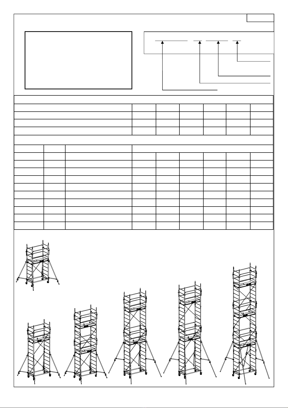
Altitude Steel 150
Norm code 11152 11153 11154 11155 11156 11157
Floor height in m. 1,7 2,8 3,9 5,0 5,6 6,7
Work height in m. 3,7 4,8 5,9 7,0 7,6 8,7
Weight in kg 90 102 132 145 149 184
Norm
Part code Weight Description Part quantity according to the product code
11101 1,4 Ø125 wheel 4 4 4 4 4 4
11102 7 AC150 base body 1 1 1 1 1 1
11105 7 2m ladder (6 rungs) 2 2 6 6 8 8
11106 5 1m ladder (4 rungs) 2 4 0 2 0 2
11107 13 AC150 floor 1 1 2 2 2 3
11110 4,5 AC150 safety rail 2 2 4 4 4 6
11113 1,4 AC150 brace 2 4 4 6 6 8
11116 7 Stabilizer 4 4 4 4 4 4
46057 0,1 Ø40 clamp pin 4 4 4 4 4 4
46070 0,1 Ø35 pin 8 12 12 16 16 20
Page 2/20
Code 11153
Code 11154
Code 11155
Code 11156
Code 11157
Code 11152

1400 mm
1570 mm
684 mm
798 mm
D040373A
11102 - Base body
11107 - Floor
11101 - Ø 125 wheel
11105 - 2m ladder 11106 - 1m ladder
11116– Stabilizer
11110 - Safety rail
46070 - Pin
11113 - Brace
46057 - Clamp pin
Page 3/20
11101
11110
11106
11107
11105
46070
46057
11113
11102
11116
Size in mm Anchoring point
of the stabilizers to the
rung, starting at the
bottom
Code Hauteur
plancher A B
11152 1,7 m 1650 1300 6th rung
11153 2,8 m 2100 1800 6th rung
11154 3,9 m 2300 2000 7th rung
11155 5,0 m 2650 2400 7th rung
11156 5,6 m 2800 2600 8th rung
11157 6,7 m 2900 2650 8ème barreau
Sabilizer's position
according to the
number of rungs.
Example: 6th
Stabilizer A min. dimensions
Stabilizer B min. dimensions

D040373A
ASSEMBLY AND USE INSTRUCTIONS
Altitude Steel 200
Norm code 11202 11203 11204 11205 11206 11207 11208
Floor height in m. 1,8 2,9 4,0 5,1 5,7 6,8 7,9
Work height in m. 3,8 4,9 6,0 7,1 7,7 8,8 9,9
Weight in kg 102 115 149 162 166 205 218
Norm
Part code Weight Description Part quantity according to the product code
11100 3,1 Ø 200 wheel 4 4 4 4 4 4 4
11103 8,2 AC200 base body 1 1 1 1 1 1 1
11105 7 2m ladder (6 rungs) 2 2 6 6 8 8 8
11106 5 1m ladder (4 rungs) 2 4 0 2 0 2 4
11108 15,6 AC200 floor 1 1 2 2 2 3 3
11111 5,2 AC200 safety rail 2 2 4 4 4 6 6
11114 1,6 AC200 brace 2 4 4 6 6 8 10
11116 7 Stabilizer 4 4 4 4 4 4 4
46057 0,1 Ø40 clamp pin 4 4 4 4 4 4 4
46070 0,1 Ø35 pin 8 12 12 16 16 20 24
Page 4/20
Code 11204
Code 11205
Code 11206
Code 11207
Code 11208
Code 11202
Code 11203
LOADING CONDITIONS
Floor: Maximum allowed load spread over the
floor = 190 Kg
Whole scaffolding: Maximum allowed load
spread over the floors = 500 Kg
Spread load class 3 (200 daN/m²)
NF EN1004 - 3 – 6,8/6,8 – D Rolling
Follow the assembly and use instructions
Reference to the norm
Class of the load evenly spread
Access type
Maximum height for
outdoor/indoor use

D040373A
11103 - Base body
11108 - Floor
11100 - Ø 200 wheel
11105 - 2m ladder 11106 - 1m ladder
11116– Stabilizer
11111 - Safety rail
46070 - Pin
11114 - Brace
46057 - Clamp pin
Page 5/20
11100
11111
11106
11108
11105
46070
46057
11114
11103
11116
1800 mm
1970 mm
684 mm
798 mm
Sabilizer's position
according to the
number of rungs.
Example: 6th
Size in mm Anchoring point of the
stabilizers to the rung,
starting at the bottom
Code Floor
height A B
11202 1,8 m 1700 1200 6th rung
11203 2,9 m 2100 1650 6th rung
11204 4,0 m 2300 1900 6th rung
11205 5,1 m 2600 2200 7th rung
11206 5,7 m 2750 2400 7th rung
11207 6,8 m 2800 2450 8th rung
11208 7,9 m 3000 2700 9th rung
Stabilizer A min. dimensions
Stabilizer B min. dimensions
This manual suits for next models
2
Table of contents


