Domino
DFPW2
DFPW2: power supply module
DFPW module generates the proper power supply required
by the modules connected to Domino bus. To ensure prop-
er operation, the input voltage of DFPW module must be
30Vac 50Hz.
DFPW performs an electronic protection with self-restor-
ing function; the protection breaks off the current at the out-
put terminals when an overload or a short circuit occurs. In
this way the traditional glass fuse is no more needed, and
all the problems caused by its replacement when an unin-
tentional short circuit occurs are thus avoided.
As additional safety, a protection fuse, connected across L
line, is however located under the cover of LN terminal
block.
A green LED (ON) and a red LED (FAIL) on the front panel
show the operating condition of the module (normal, criti-
cal, protection) as described in the following.
DFPW can supply up to 50 modules of weight 1 (*) of
Domino family. If the amount of installed modules overrides
this limit, or if the bus is very long, then more DFPW mod-
ules must be installed in different locations (if possible), in
order to distribute them along the bus and minimize the
voltage drop.
(*)
Domino
modules have, in large part, a current consumption
which is defined as weight 1; some special
Domino
modules have
a current consumption of higher weight. For example, if a module
has weight 4, then this will absorb a current equal to 4 "standard"
modules. The table in the next page resumes the modules having
weights different from 1.
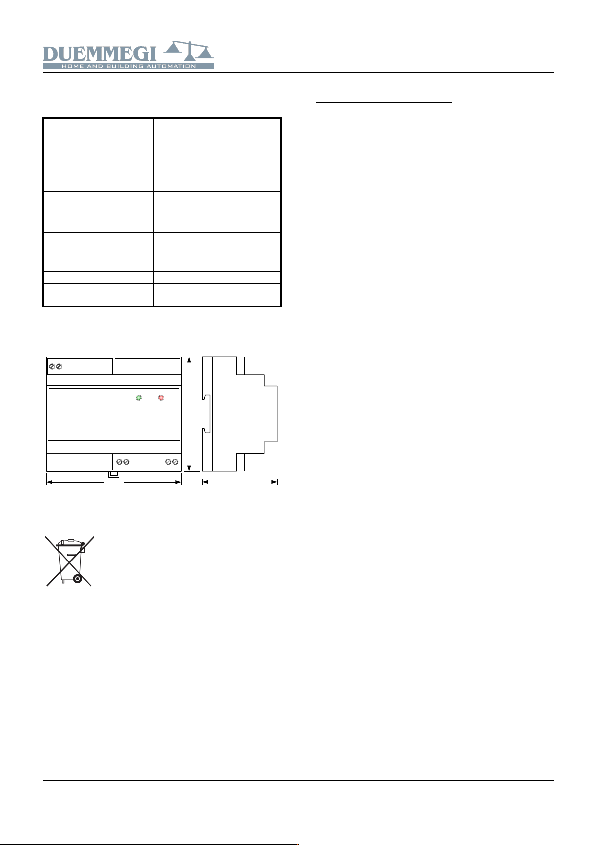
DFPW housing is a standard DIN 6M module and it pro-
vides a -pole terminal block for the connection to the input
voltage ( 30Vac) and a pair of -pole terminal block (+ and
-) for the connection of Domino bus; the doubling of the +
and - bus terminals (internally parallel connected) allows, in
some cases, to simplify the wiring. On the contrary of the
majority of other Domino modules, DFPW module does
not require any address.
Protection operation
When the output current of DFPW module overrides a first
fixed threshold, the green LED on the front panel begins to
blink to inform that the module is operating in the critical
zone, even if it continues to supply the current on its output.
If the current overrides a second threshold, then the elec-
tronic protection takes place breaking off the output circuit
by means of an internal power relay; in this case the green
LED will be switched off and the red LED will be switched
on. The protection, after the first overload occurrence, will
be restored after 5 seconds, but if the current is higher than
the second threshold once more, the protection takes place
again and it will be restored after 10 seconds. If the over-
load condition persists after the second restoring too, then
the following restoring attempts will occur every 30 sec-
onds.
The following table resumes the waiting times before the
restoring as function of the amount of the consecutive pro-
tection occurrences:
Protection occurrence Restoring after
After the first occurrence 5 seconds
After the second occurrence 10 seconds
After the third occurrence 30 seconds
After the next attempts 30 seconds
The following table describes the meaning of the signals
provided by the two LEDs on the front panel:
Green LED Red LED Meaning
Fixed ON OFF OK
Blinking OFF Critical operation
OFF Fixed ON Protection occurrence
Module connection
Following figure shows the proper connections to be made
for DFPW module.