Duevi DIRVE K User manual

This manual can be modified without any warning
We thank you very much for choosing our item.
Now we would like to invite you to read carefully the following
instructions before installing the product in order to use all its capacities.
DIRVEK
LOW CONSUMPTION IR OUTDOOR DUAL SENSOR
MANUAL VERSION 0.5
The above symbol guarantees that the item complies with EU norms (EUROPEAN
COMMUNITY) on devices that can generate interferences. The acronym CE means
Conformitèe Européenne (EUROPEAN CONFORMITY). All our equipment are certified
accordin
g
the EU norm and are also certified PPTT.

This manual can be modified without any warning 2
SUGGESTIONS and PRECAUTIONS
Warning: DIRVE K has been designed to guarantee a very high immunity to light
interference, however very bright light can produce instability. It is therefore recommended
to take great care in installation to avoid direct or reflected sunlight or high intensity light
beams.
Warning: It is recommended to use the outdoor sensor as an additional tool to a security
system and not for activating directly alarm tools as sounders and phone diallers.
Warning: Avoid to orient the sensor towards moving objects such as bushes, flags,
branches etc, because it may cause an unwanted relevation.
Warning: In outdoor installation, it is recommended to use the sensor in the “AND” mode
for higher security and to set both beams in the same direction. Incorrect installation could
reduce security level.
Warning: If possible, avoid to installing the sensor in areas directly exposed to rain or
snow. Do not spray any water on the sensor.
Warning: If you do not comply with the above-mentioned precautions, it may cause a
malfunction and in such an event, the manufacturer will decline any responsibility.
INSTALLATION SUGGESTIONS
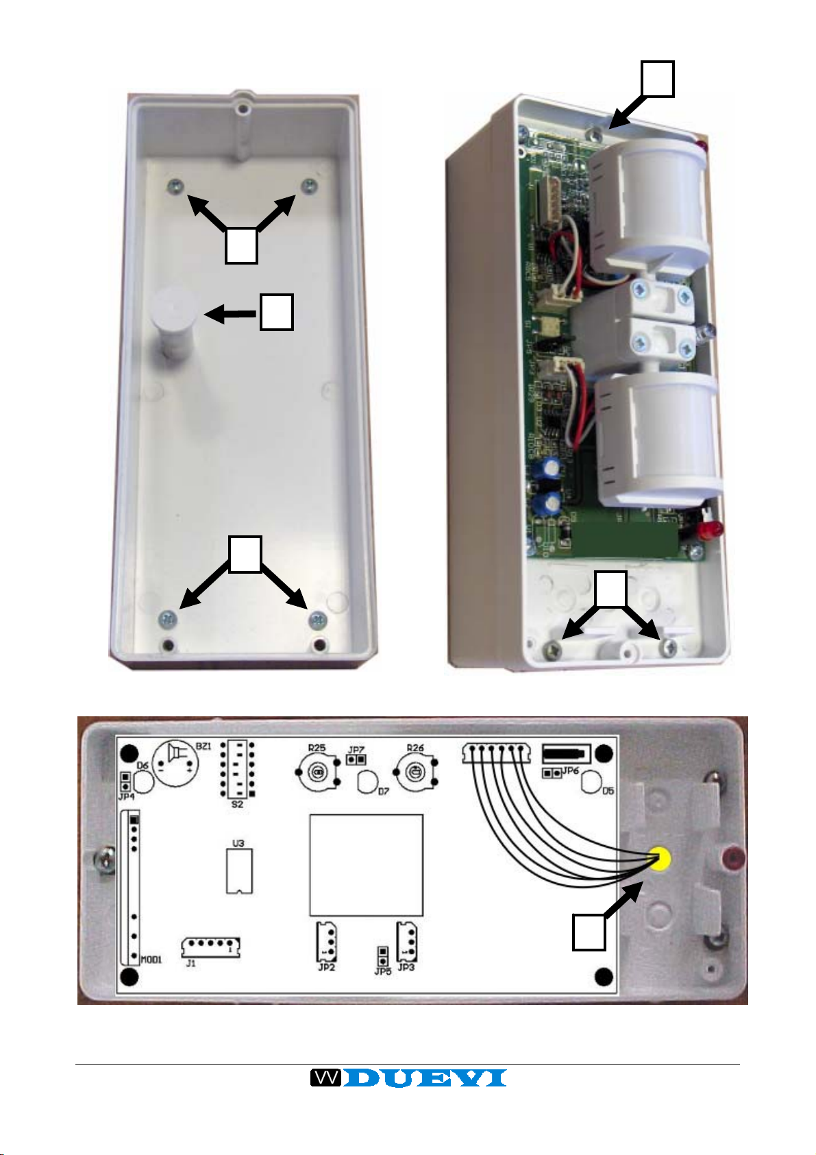
DIRVE K sensor can be fixed at heights between 50 and 250 cm, on vertical surfaces,
walls or posts, using the anchor clamp and protection (item STAK). Obviously the
detection units MUST be oriented horizontal or facing downwards, never upwards, in order
to avoid situations of blinding by sunlight during the day and to safeguard the good running
of the sensor.
The two detection units MUST be positioned on the vertical axis, so that the two beams
cause slight divergence to detect an intruder with human form and not animals or objects
that you do not want to be considered intruders.
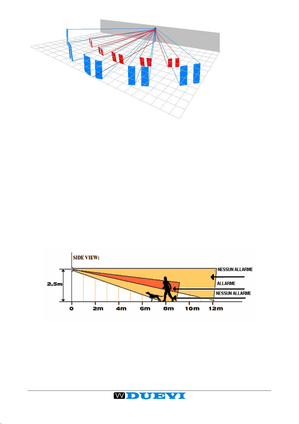
Looking at Fig. 1 and 2, you will notice that it is possible to detect the intrusion of a man
from a distance of 8 m from the sensor avoiding the animal’s detection by tilting the lower
unit more strongly downwards in comparison to the upper unit.
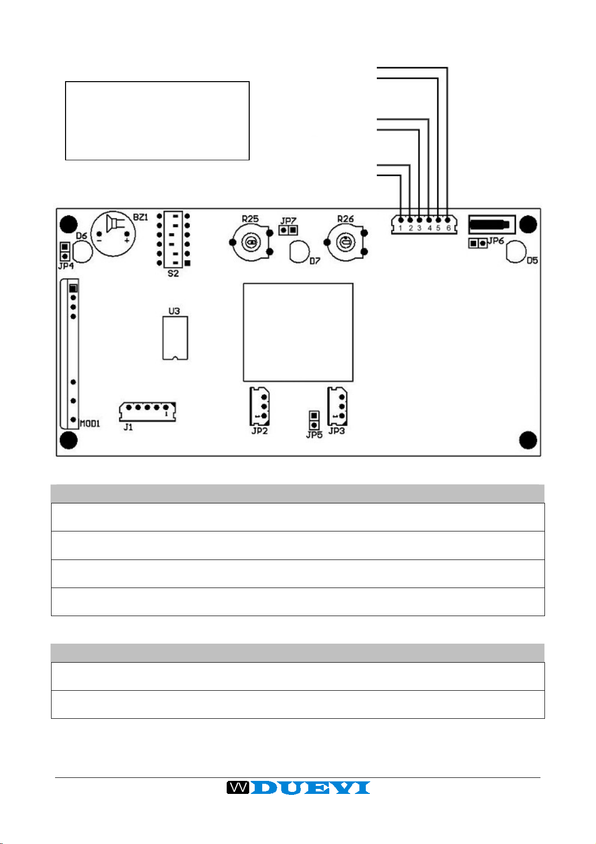
Each detection unit has 5 double horizontal beams oriented on a 100° aperture.
In some cases, such width of sight can be a problem if the detection area is not clear due
to branches, curtains, glass window etc.
If this does occur, you need to reduce the area by masking the side or intermediate beams
with some white adhesive tape over the sections of unit lenses (beams blinding), so that
the beams are only oriented on stable zones of detection.
This precaution avoids unwanted alarms raised by wind, moving branches, curtains or
other objects present in the area.

This manual can be modified without any warning 3
FIG.1 Prospectic view of covered area
It is possible to orientate the detecting units in opposite directions horizontally, in order to
prevent triggering an alarm if only one sensor detects movement. Only the crossing of both
covered areas of the two detection zones will be considered an alarm. This mode is useful
on balconies, terrazzos or corridors, where movement in only one direction is unavoidable.
Furthermore it prevents unwanted alarms, due to people moving on adiacent areas.
It can also be set the “intelligent AND” mode, that programs the sensor only to trigger a
real alarm when the sequence begins with the A beam (upper detecting unit) and ends (in
the “AND” time) by detecting the B beam.
This function permits a directional detection, in other words it allows the sensor to detect
an approach towards the protected area avoiding detections of movement on a nearby
area.
You should also consider that the regulation of the detecting units has to be very
meticulous, as small alterations of the position, over a length of 8 m, cause large
movements of the beams.
FIG. 2 “Intelligent AND”: human is detected by the crossing of both the beams, the dog
doesn’t alarm the sensor
It is therefore suggested to keep the screws relaxed during the orientation of the heads.
When this operation is complete, screws should be fully tightened. As the cover causes an
attenuation of about 30% of the length of the beams, this should be also considered during
the setting (without cover).

This manual can be modified without any warning 4
Due to the detecting units feature of being able to rotate on all axes, it is also possible to
place the sensor on a slanting wall upwards without using further clamps, however
detection from lower beams should be lost. Reducing the mounting height can
compensate for this loss.
For a sure and repeatable detection, it is suggested to install the sensor in order to have
the intruder that moves accross the beams and not toward the sensor.
The more interesting feature of this infrared sensor is to have two different and completely
independent detection heads that can be orientated separately. This allows the infrared
sensor to function in “OR/AND” mode. If turned to “OR”, when one of the two sensors
detect a movement, an alarm is triggered. When turned on “AND” mode,only detection by
both sensors will create an alarm signal. Furthermore it is possible to select the priority of
the head that triggers the alarm. This means higher security and less risk of “unwanted
alarms”. The optical range is 8m per ray.
Sensor use:
Mount the sensor taking account of a max coverage area of 8 m in distance and a max.
angle of 100° (see fig. 1).
Fix the bottom of the sensor with the 4 fisher screws included (Ø6mm – screw 3,5x35mm
– see points in figure).
Insert the extension for the Tamper protection (see in figure).
Drill the sensor case in the point and pass through the hole the signalling wires to be
connected to the wireless transmitter.
Put the wireless transmitter in the empty case behind the sensor and fix the sensor with
the 3 included screws (2,9x19mm – see points )
To set the sensitivity of the detectors, start from a minimum setting condition i.e.
regulation trimmers turned in an anticlockwise direction and detectors placed at the
lowest possible position. Increase gradually the range of detection only in the area you
want to protect, in order to avoid the risk of detecting insignificant movements and
unnecessary alarms.
AFTER POWERING THE SENSOR, IT IS ACTIVATED AND STABILIZED ONLY 20
SECONDS AFTER THE END OF FLASHING RED LED’S.
D
C
B
A

This manual can be modified without any warning 5
A
B
A
C
D
D
A
B
A

This manual can be modified without any warning 6
O-RING MOUNTING
DIRVE K is provided with 5 silicon O-RINGS to be mounted on the sensor for a good
weather protection.
The O-RINGS are in different colors (black and red). It is mandatory to respect the
position of the different colors, because they have different purpose and if they are
scrambled it is not guaranteed a good weather protection.
BLACK O-RINGS
(1-2-3-4)
Mount the o-ring on the
screws body in order to
realize a perfect tight under
the screw head.
1
3
2
5
4
RED O-RINGS
(5)
Mount the o-ring in the
groove where tigheten the
cover screw.
TAMPER COVER
DO NOT REMOVE AND
DO NOT DRILL!!!

This manual can be modified without any warning 7
FUNCTIONS SETUP:
JUMPERS
JP5 Wall Tamper Closed = tamper disabled
Open = tamper enabled
JP6 Cover Tamper Closed = tamper disabled
Open = tamper enabled
JP4 Test Buzzer Closed = Buzzer disabled
(only with DIP4 ON) Open = Buzzer enabled
JP7 Alarm Blue Led Closed = led enabled
Open = led disabled
IR HEADS RANGE TRIMMERS
R25 Upper IR Head Sensitivity setting of upper head. Turn in clockwise
direction to increase the range.
R25 Lower IR Head Sensitivity setting of lower head. Turn in clockwise
direction to increase the range.
TAMPER
OUTPUT
LOW BATTERY
OUTPUT
ALARM
OUTPUT
ALL THE OUTPUTS ARE N.C.
(NORMALLY CLOSED) FREE
VOLTAGE CIONTACTS
•CLOSED IN STAND-BY
•OPEN WHEN ACTIVE

This manual can be modified without any warning 8
DIP-SWITCHES
DIP1 Sensor Logic OFF = AND mode for the heads
ON = OR mode for the heads
DIP2 IR Sensitivity OFF = High sensitivity (indoor use)
ON = Low sensitivity (outdoor use)
DIP3 AND mode
selection
(with DIP1 OFF)
OFF = NORMAL AND
Alarm is triggered by a detection that starts from any head
and ends with the detection of the second head. If during the
“AND time” the second head does not detect anything, the
sensor returns in stand-by mode.
ON = DIRECTIONAL AND
Alarm is triggered by a detection that starts from the upper
head and ends with the detection of the lower head. If during
the “AND time” the lower head does not detect anything, the
sensor returns in stand-by mode.
DIP4 Test OFF = Normal use (Test OFF)
ON = Test Mode
Enables head detection leds, alarm led and buzzer (if JP4 is
closed), useful during the test of the detection area.
OFF = Normal use
DIP5 Continuous
Transmission ON = the sensor make a cyclic switch of the alarm output
(with 1 sec. period), useful for testing the range of the wireless
transmitter).
DIP6
(*) Quiet Time OFF = Quiet Time enabled
Alarm is triggered only if, between two detections, occurs a
time gap of at least 30 seconds. If, within this time, there is
another detection, the sensor resets the quiet time. If no
detection is recorded after the quiet time, the sensor is ready
to trigger a new alarm. This function is particularly useful in
very crowded places, to extend the battery life.
ON = Quiet Time disabled
Alarm is triggered each time the sensor detects a movement.
(*) NOTICE: When DIP6 is moved from OFF to ON, before to obtain a real change of
the function, it is necessary to wait the quiet time without causing any detection,
otherwise the sensor will continue to work the same as with DIP6 in OFF.

This manual can be modified without any warning 9
TECHNICAL FEATURES
POWER SUPPLY Battery 9V
CONSUMPTION Stand-by < 15uA – ALARME < 10mA
SIGNALLING 1 LED for upper head, 1 LED for lower head, 1 LED for alarm transmission
ALARM INPUTS 2 sensible elements, with selectable OR/AND mode
TEST Test function selectable by dip-switch with led display and buzzer
WIRED OUTPUTS Alarm, Tamper, Low battery
Table of contents
Other Duevi Accessories manuals
Popular Accessories manuals by other brands

Viessmann
Viessmann VITOTROL 200 RF Installation and service instructions

Vivint
Vivint SmartHome Doorbell Camera Pro quick reference

FRIMETAL
FRIMETAL MVP Series instruction manual

ELMEKO
ELMEKO PK 75 Installation and operating manual

ring
ring Pro Power Setup and installation guide

Aceinna
Aceinna MCA1101-5-5 Evaluation Note