Duevi Photon System Operating and maintenance instructions

PHOTON SYSTEM –Installation Guide v8.0 - pag.1
PHOTON SYSTEM
Installation Guide
(rel. 8.0)
Fig. 1
General description of the system
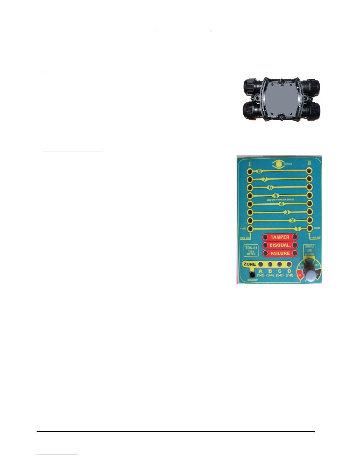
The Photon system by Deitech, in its basic configuration, is
made of two bars absolutely identical (Fig. 1), placed at the two
ends of the area to be controlled thus creating an “infrared
barrier”; the bars are connected with just one cable to a hub
(Fig. 2), that, placed in the Control Unit, controls the whole
system. The bars are used for both transmission and reception
of the beams, work in couple and exists in different versions:
from 50 to 200 cm height, with or without heather, with maximum
range 25, 50 and 80 meters. They have all the same design; are
made of an aluminium body with a black polycarbonate cover
and two caps of the same colour.
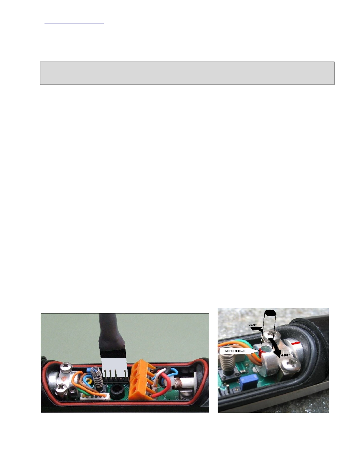
On the “ROTAX” cap (Fig. 3) you can
find the connection terminals and the
ROTAX system for the orientation of
the beams. On the “NUMBER” cap
(Fig. 4) there is the selector for the ID
number to assign to the bar and, in the
models with heater, the terminal blocks
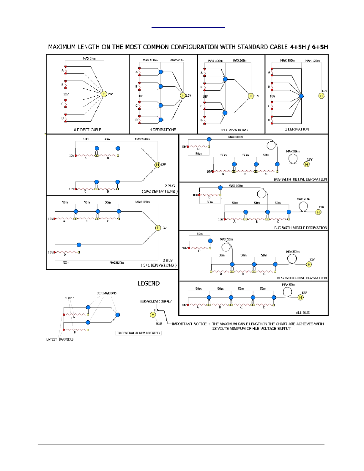
for heater power supply. Through a four
wires cable plus shield, the barriers
(from ROTAX cap) will be connected to
the hub; the connection could be a star
or in series so that it can easily adjust
to the different installation
requirements.
The hub controls the correct operation of the barriers, allows the configuration of the system
and concentrate the connexion with the control panel. The hub will manage up to a maximum
of four couples, that can be installed even in the same area and the beams will not interfere
between themselves. The four couples can be of different heights and different range but the
bars of each couple must be the same. For each couple the hub will allow to set different
operation parameters (see HUB-TC Manual for details) and manage single stand-by inputs.
The alarm output toward the control panel are different for each couple, while the technical
outputs (tamper, disqualification, failure) are common for all the couples managed by the hub.
If the installation will require more than four couples, then more hub are needed.
THE BARS
It’s absolutely fundamental to install the couple of bars properly, each couple must be placed in order
to protect the passage through which an intruder could pass. In order to determine the correct mounting
height of the bar, it must be taken into consideration that the first beam (and the last) is placed at about
20 cm from the end of the bar and that between the other beams there are 25 cm. The barrier can be
placed upside down to connect the hub either from above or from below, but it is mandatory that each
couple is installed in the same position. All the Photon barriers have a patented system that allows a
correct horizontal alignment of the beams (ROTAX). This system will enable the installer to install them
Fig. 2 –hub-tc
Fig. 3 –rotax cap
Fig.4 –number cap

PHOTON SYSTEM –Installation Guide v8.0 - pag.2
on surfaces that not necessarily are placed in front (Fig. 5).
Oblique installations can than be easily made (Fig. 6) with a
maximum angle of 90° between the walls i.e. the barriers
can be installed on the same wall (Fig. 7). The ROTAX (Fig.
17) is the rotating element that has to be used in order to
direct all the beams in the range +/- 90°.
The bars are equipped with two tamper systems. The first
one (that cannot be deactivated) is located on the cap’s
opening and goes in alarm every time the cap is open. The
second will reveal the removal of the bar from the surface
on which it is installed and can be deactivated if not used.
Inside the bar there are two red led that can flash if the
hub have the led option enabled: one will signal a tamper
alarm i.e. that at least one of the four tampers is open, the
other one light on when the barrier is in “alarm” condition.
The ice can divert the direction of the beams; it is possible
to order a version of barrier with integrated heating system
(the not “heated” ones cannot be modified later). These bars
are suggested for external installations and anyway in cold
and humid environments. The heating system, managed by
a thermostat, will guarantee the functioning up to -20° C..
Fig. 5
Fig. 6
Fig. 7
Cabling the bars
After having set where the bars have to be placed, it will be necessary to position the connecting wires
between the hub and the barriers. In a standard installation (bars positioned at a maximum of 200-300
mts from the hub) a standard 4 wire cable (two for power supply 0,75 mm2, 2 for the serial communication
0,22 mm2) and shield.
The number of possible connection typologies is quite wide and for each one of that the maximum
length of the cable may vary; Fig. 23 represents some examples with the maximum cable length.
Warning the maximum length of a cable connected to a single barrier is 1000 mts.
For the connection of the wirings, there are available waterproof interconnection boxes (Fig. 18), that
contain a terminal blocks that allows to derive from the bus two wires for the couple.
Fig. 24 represents an example of a connection of a complete system.
If the bars are the heated version, for the installation of the heating power cables you have to refer to
adding section of this manual.
Fixing the bars
The bars must be fixed on walls or supports that should be as much as possible flat and plumb; in case
it is advisable to use plies to correct and to fill the surface making it flat. If there is no intention to use the
anti-removal tamper it is sufficient to lean the bar on the support and, after having plumbed it, mark the
holes for the screws trough the holes of the two caps (see drawings attached at the end of this guide).
WARNING: TIGHTEN ONLY ONE OF TWO FIXING SCREWS AND LEAVE MOVING POSSIBILITY
TO THE SECOND SCREW, TO ENSURE THE PROFILE OF BARRIER FREE TO EXPAND /
CONTRACT FOR THERMAL EXPANSION.
BAR MUST NOT BEND UNDER ANY CONDITION, OTHERWISE IT WILL AFFECT ITS PROPER
OPERATION.
Anti-removal tamper activation on the bars (optional)
The anti-removal tampers are two waterproof buttons which are integrated in the rear of each cap and
are encased in order to avoid tampering attemps from outside..

PHOTON SYSTEM –Installation Guide v8.0 - pag.3
In order to keep each tamper pressed it is sufficient a head of a screw that stands out for from the wall
about 3/4 mm. The anti-removal system requires a certain precision of installation. For this purpose a
mask is supplied that shows the exact point where the screw has to be inserted. The head of this screw
will stand out for minimum 3 mm and not more 4 mm. If plies have been used, then the distance of the
screw’s head must be adjusted according to the needs. Once the bars have been fixed, remove the
jumper J1 on the ROTAX cap and J2 from the NUMBER cap and verify with a tester positioned on the
two pins of the J1 or J2 jumpers that the contact is closed; if it appear as open than that mean that the
screw does not stand out enough. Warning do not protrude the screw more than 4 mm in order not to
damage the micro-switch button.
Cable connection inside the bars
The cable connection is made in the following steps:
1) Prepare the cable (Fig. 8 A / B).
2) Insert the cable in the cable gland (Fig 9).
3) Fold the cable shield backwards and lean it on the metallic holder (Fig 8 C / D).
4) Block with a strip the cable to the holder (Fig 8 E / F).
5) Cut, shear and fix the 4 wires into the terminal blocks and tighten the cable gland (Fig 10).
WARNING: USE EXTRA CARE IN THE TIGHTENING OF THE CABLE GLAND. WRONG CLOSING
AFFECTS HEAVILY THE WEATHERPROOF IP65 LEVEL OF THE BARRIER AND WILL VOID THE
PRODUCT WARRANTY.
Fig 8
Fig 9
Settings of the bars
In the bars there are two settings to do. The first one will enable the anti-removal tamper. Whenever
you want to activate it you will have to remove the two jumpers that are placed in the NUMBER and in
the ROTAX caps. The other relates to the ID number of each bar (address).
Addressing the bars
Each Hub can manage up to four couples (i.e. 8 bars) and each bar must be precisely identified with
a univocal number on the bus. This will be set by jumper that can be found in the cap “NUMBER”.
Fig 10

PHOTON SYSTEM –Installation Guide v8.0 - pag.4
The ID number of the bar (address) must be set as follows:
1 and 2 for the first couple (zone ‘A’),
3 and 4 for the second couple (zone ‘B’)
5 and 6 for the third couple (zone ‘C’)
7 and 8 for the fourth couple (zone ‘D’).
NOT HEATED version has a double row of contacts on which a jumper is inserted in the position
corresponding to the address to assign to the bar (Fig 11).
Fig 11 –Addressing of the NOT HEATED version
HEATED version, due to the presence of the heater, has a single row of contacts on which a jumper
is inserted in the position corresponding to the address to assign to the bar (Fig 12). Pay great attention
to this, because due to the small space available, it is easy to fall into error.
Fig 12 –Addressing of the HEATED version

PHOTON SYSTEM –Installation Guide v8.0 - pag.5
The HUB-TC
Connection between HUB-TC and barriers
The connection with the bars can be made only through the 5 terminals of the hub (Fig. 25). Do not
connect the bars to different supplies than the one foreseen and be very careful not to invert the serial
poles S2 and S3. Fig. 24 represent an example of the connection of a complete system.
Terminals description:
S1 = Negative power supply (0V) minimum section 0,75mm2
S2 = RS485 pole A minimum section 0,22mm2
S3 = RS485 pole B minimum section 0,22mm2
S4 = Positive power supply (+12Vdc) minimum section 0,75mm2
GROUND = Shield of the cable
WARINING: THE CABLE SHIELD MUST BE CONNECTED BOTH ON THE BARS AND ON THE HUB SIDE.
Connection between HUB-TC and Control Panel
The hub is made in such a way that it can be installed inside the Control Panel Case or in any other
protected case. Use the holes foreseen in the Hub for its fixing. The connection will be made by the cabling
of the wires between the terminal blocks of the Hub (Fig 25) and the Control Panel.
It is recommended to use for the power supply at least two wires of minimum section 0,75 mm2.
Terminals of the HUB-TC toward the Control Panel
Terminal
Description
Contact type
sA
sB
sC
sD
Stand-by command inputs.
To be connected to the Control Panel if you intend to
manage the stand-by separately. They can also be
connected all together in order to have not separate
stand-by for the different couples. When the barriers
are in stand-by, the beams are not active (this means
energy saving and less component consumption) but
the tampers and the failure are active.
Zone enabled = free or GND
Zone disabled = +12Vdc
FL
Failure Output. Normally open, it is closed at ground
when malfunctioning is detected (fault, wire
interruption, etc.)
OPEN COLLECTOR
Normal = free (max 200VDC)
Failure = to GND (max 100mA)
DQ
Disqualification output. Active only if the option is
enabled on the HUB. Normally open, it is closed at
ground when, due to limited visibility conditions (fog,
very heavy rain), the barriers cannot operate properly.
It will return open as soon as the environmental
conditions go back to optimal.
OPEN COLLECTOR
Normal = free (max 200VDC)
Disqualification = to GND (max
100mA)
TAMP
Tamper Output. Normally closed. It is open when
one of the tamper is activated.
Closed=20 Ohm (max 100 mA)
Open= infinite (max 200 VAC-DC)
ALRM
General Alarm Output. Normally closed. It is open
when the system detects an alarm on one of the
connected barriers.
Closed=20 Ohm (max 100 mA)
Open= infinite (max 200 VAC-DC)
A-B-C-D
Zone Alarm Outputs. Normally closed. It is open
when the single barrier detects an alarm.
Closed=20 Ohm (max 100 mA)
Open= infinite (max 200 VAC-DC)
-+
Power supply Input. It power the hub which in turn
distributes the power to all the connected bars.
Form 9 to 16 VDC
Max 0,9 A (Hub + 8 bars)

PHOTON SYSTEM –Installation Guide v8.0 - pag.6
WARNING:
CONNECT THE METALLIC BASE OF THE HUB TO THE ELECTRIC PLANT GROUND.
Settings on the HUB-TC
The HUB-TC allows you to centralize the monitoring and configuration of installed barriers couples,
through the use of 3 free software:
PHOTON TEST HUB (barrier and cabling verification)
PHOTON SETUP HUB (setting of the barrier parameters)
PHOTON MONITOR HUB (real-time monitoring and activity log of the barriers)
For the use of the software you need to connect to the RS232 port of the Hub (Fig 25)
Switch on and check of the system
Once all the cabling have been done, it is necessary to verify the connection and correct setting of
the HUB.
WARNING. This is just a summary of what to do. Please see the HUB-TC manual for the step by
step procedure of system verification and programming of the system.
1) Set DIP1=ON, DIP2=ON and power the system. After few seconds the led is solid on. If the led is
off, check the power cables of the HUB.
2) Use the software PHOTON TEST HUB to verify that all the address of the connected bars are
detected by the software (1-2-3-4-5-6-7-8). If some bar is not detected, check that the addresses
on the bars and the connections are correct, then make again the test. Do not go to the next step
until any connected barrier is detected.
3) Use the software PHOTON SETUP HUB to program the working parameters of each couple.
WARNING: Enable only the barrier couples that are really connected to the system (A-B-C-
D), otherwise the HUB will not start correctly and will signal continuously a FAILURE.
4) Set DIP2=OFF and press reset button on the HUB to restart.
5) After few seconds, check the proper operation of the Hub with the continuous quick flashing of led
(Fig 25). If the led is solid on or flashing in a different way, it means that the HUB is in FAILURE
mode, so you have to check again the previous steps (check the cables to the bars, the enabled
couples A-B-C-D, the correct addressing of the bars –Fig 11).
6) If the HUB gives tamper alarm and all the caps are already closed, please check the proper
closing of the caps. If some cap is open, then it is a correct alarm condition.
7) At this step you have to start the beam adjusting procedure and it is normal that, as it is not
performed yet, the HUB can give alarm or disqualification condition.

PHOTON SYSTEM –Installation Guide v8.0 - pag.7
Beams alignment
In order to correctly align the beams it’s necessary the use of the field tester TBS.
The field tester (Fig. 19) it’s a device that allows to check in a very deep way the behaviour of every single
beam within a couple of bars.
WARNING: DO NOT LOOSEN THE SCREWS INSIDE THE CAPS. THEIR TAMPERING WILL AFFECT
THE SEALING OF THE DECLARED IP LEVEL, AS WELL AS WILL VOID THE WARRANTY RIGHT
(SEE FIGURE 26)
Proceed as follows (refer to TBS meter manual for more details):
1) Enter in “OPTIC ADJUSTMENT” mode, set DIP1=ON, DIP2=OFF and press the reset button on the
HUB to restart (Fig 25).
2) Remove any obstacles between the bars to be aligned.
3) Go to the first bar of the couple to be aligned and open the ROTAX cap to access the pivot that
allows the alignment of the beams (Fig 17)
4) Insert a small tool into the ROTAX pivot hole and make a rough alignment by eye (i.e. the beam of
each bar should be directed toward the other bar), keeping in mind that the IR led emission is in the
direction on the red sign on the ROTAX (Fig 17)
5) Do the same operation on the other bar of the couple.
6) Connect the TBS tester to dedicated plug inside the ROTAX cap (Fig 16)
7) Turn on the TBS tester and move the attenuation knob in MED position
8) Select with the SELECT button the zone you want to align (A-B-C-D)
9) Observe the LEDs of the single rays and turn the ROTAX left / right so that gradually all the LEDs
of the single beams are switched off, while the alignment improves
10) Do the same operation on the other bar of the couple.
11) When all the ray’s LED are off, move to attenuation knob into HIGH position, if there is any LED on,
very slowly rotate the ROTAX to turn them off, you can continue to increase the level and orient
more and more finely the ROTAX in order to obtain a better coupling, but if all the leds are off with
the knob in position "HIGH", it means that the infrared signal transmitted and received is at an
optimal level and alignment may be considered concluded.
12) Do the alignment operation for every couple of bars connected to the hub
13) Exit from “OPTIC ADJUSTMENT” mode, set DIP1=OFF, DIP2=OFF and press the reset button on
the HUB to restart (Fig 25).
Fig 16 Fig 17

PHOTON SYSTEM –Installation Guide v8.0 - pag.8
ACCESSORIES
The PHOTON system provides various accessories to expand the performances and to assist installer
in his work. Following is a list of some of them with a short description, detailed instructions for use are
however provided in the product box.
Derivation box –SCAP68
The junction box SCAP68 (Fig 18) allows to derive the connection
cable between HUB and bars in two or three outputs for up to three
bars. They are waterproof with IP68 level.
In Figure 24 there is an example of use of the junction boxes for a
complete system.
Fig 18
Field tester - TBS
This is a tester (Fig. 19) to be used to optimize the alignment
during the installation.
It monitor in real time the reception of the signal. Thus by moving
the ROTAX pivot you will obtain a perfect alignment of the beams.
The tester will be connected to the dedicated plug inside the
ROTAX cap of the bars (Fig. 26). It is sufficient to connect to any
of the bars or to the HUB to check the whole system.
Though a selector you can select the couple to be monitored and,
by regulating the attenuation knob, you can analyze if the beams
are correctly aligned, if someone is too low or even faulty.
The tester also show possible disqualification status; this is useful
when installing the barriers outside not only because you can verify
the correct alignment but also if the distance between the couple is
corretly set.
The signal of “tamper” and “failure” will allow you to immediately
find which bar is not properly installed.
The tester is a device very useful, versatile and of easy usage
and it becomes mandatory for the installer that is facing quite
complex installations. It is also very useful for simpler installations
because it make the installation very faster dramatically cutting the
time for aligning the barriers, which is at the base of a correct
functioning of the system.
Figura 19

PHOTON SYSTEM –Installation Guide v8.0 - pag.9
Monitoring Software
The Hub allows the connection to a PC, via
RS-232 port, for monitoring the system.
For this purpose is included the software
PHOTON MONITOR HUB (Figure 21), which
can monitor and archive everything happens in
the system.
The software allows you to store all system
events, with the time in which they occurred.
This allows you to keep track of them for many
months.
Through a query mask, it is possible a quick
analysis of stored data in order to identify quickly
if and when there were abnormal events.
Through a generic remote control software it is
possible to carry out monitoring at any distance.
Fig 21
Fig 22

PHOTON SYSTEM –Installation Guide v8.0 - pag.10
SUMMARY TABLES
Fig 23

SISTEMA PHOTON - manuale d'installazione - pag.11
Fig 24

SISTEMA PHOTON - manuale d'installazione - pag.12
Fig 25
Fig 26
WARNING: DO NOT LOOSEN SCREWS (1-8)
INSIDE THE CAPS
THEIR TAMPERING WILL CAUSE LOSS OF WARRANTY RIGHTS, AS WELL AS LOSS
OF THE DECLARED IP LEVEL
CABLE GLAND MOUNTING
MANDATORY
THE SUPPLIED CABLE GLANDS ENSURE
THE IP65 GRADE.
IT’S MANDATORY FOR THE INSTALLER
TO MOUNT THEM PROPERLY.
THE NON-COMPLIANCE TO THIS
RECOMMENDATION HEAVILY AFFECTS
THE OPERATION AND WILL CAUSE LOSS
OF WARRANTY RIGHTS.

SISTEMA PHOTON - manuale d'installazione - pag.13

SISTEMA PHOTON - manuale d'installazione - pag.14
HUB-TC

SISTEMA PHOTON - manuale d'installazione - pag.15
ADDED NOTES FOR THE HEATED BARS
Structurally and conceptually identical to the not heated barrier, the heated barrier differs only for the
presence of a resistive element assembled for the whole length of the barrier. A built-in thermostat
automatically balance the internal temperature thus avoiding the ice formation on the surface whenever the
outside temperature reaches the 0 degree Celsius, condition that could modify the proper optical operation
of the system.
The switching on of the thermostat and subsequently of the heather is visualized by a led positioned inside
the bar close to the number cap.
The heated bars require an extra supply assured by an external AC power supply, whose connection is
assured by two terminals positioned inside the number cap (Fig. 1), opposed to the rotax cap.
The following scheme will show the minimum section of the wire to be used for a connection to a maximum
distance of 50 mts from the power supply.
In any case the external diameter of the connection cable must not be more than 6,8mm
MODEL
VOLTAGE
COURRENT
POWER
WIRE
SECTION
EB-200R
24 V AC 50-60Hz
3 A
72 W
1,5mm2
EB-150R
18 V AC 50-60Hz
3 A
54 W
1.5mm2
EB-100R
12 V AC 50-60Hz
3 A
36 W
1.5mm2
EB-50R
6 V AC 50-60Hz
3 A
18 W
1.5mm2
FIG. 1
CAUTION: In order to assure the IP grade protection it is mandatory to use wire with sheat. DO NOT USE
FLAT CABLE OR SINGLE WIRES
WARNING: The AC power supply of the heathers must be a reinforced insulation type and must be
protected against short circuits. Beside before the power supply must be used a main circuit breaker that
allows to switch off for maintenance work on the barriers or to totally disable the heating during summer
time.
The product is guaranteed only if it is installed in a professional manner and in a state of the art following
all the instructions given. No responsibility can be blamed on the manufacturer for damages deriving from
bad installations and/or defective electrical connections.

SISTEMA PHOTON - manuale d'installazione - pag.16

SISTEMA PHOTON - manuale d'installazione - pag.17

SISTEMA PHOTON - manuale d'installazione - pag.18
WARNING: Tighten only one of two fixing screws (a) and leave moving possibility to the
second screw, to ensure the profile of barrier free to expand / contract for thermal expansion.
The bar must not bend under any condition, otherwise it will affect its proper operation.

SISTEMA PHOTON - manuale d'installazione - pag.19

SISTEMA PHOTON - manuale d'installazione - pag.20
Table of contents
Other Duevi Accessories manuals